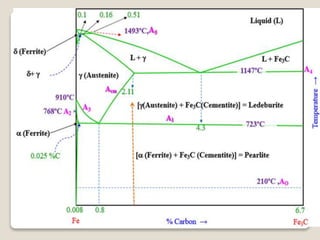
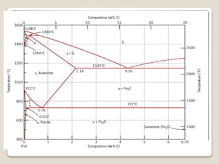
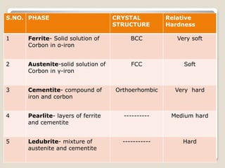
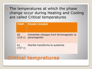
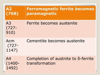
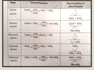
Iron – Iron Carbide
(Fe-Fe3C)
Phase diagram
BY
SK.ABDUL SALEEM
Asst.Professor (Mech Dept.)
TOPICS
INTRODUCTION
chart
SOLID PHASES
CRITITICAL TEMPRATURES
INVARIENT REACTIONS
INTRODUCTION
 Metals and their alloys are widely used in
industry
 The steel is an alloy of iron and carbon
(c=2% max)
 It is the most imp. Engineering metal and its
properties can be improved by heat treatment
 The part of iron-corbon diagram described
represents the portion between pure iron and
iron-carbide 6.67% of corbon by weight.
Solid phases
δ- iron
Ferrite
Austenite
Cementite
Pearlite
Ledubrite
S.NO. PHASE CRYSTAL
STRUCTURE
Relative
Hardness
1 Ferrite- Solid solution of
Corbon in α-iron
BCC Very soft
2 Austenite-solid solution of
Corbon in γ-iron
FCC Soft
3 Cementite- compound of
iron and corbon
Orthoerhombic Very hard
4 Pearlite- layers of ferrite
and cementite
---------- Medium hard
5 Ledubrite- mixture of
austenite and cementite
----------- Hard
Critical tempratures
 The temperatures at which the phase
change occur during Heating and Cooling
are called Critical temperatures
TEMP. PHASE CHANGE
A0
(210 c)
Cementite changes from ferromagnetic to
paramagnetic
A1
(727 c)
Pearlite transforms to austenite
A2
(768)
Ferromagnetic ferrite becomes
paramagnetic
A3
(727-
910)
Ferrite becomes austenite
Acm
(727-
1147)
Cementite becomes austenite
A4
(1400-
1492)
Completion of austnite to δ-ferrite
transformation
Invarient Reactions
. Invariant reaction is one at which the
degree of freedom is zero (F=0)
 Point on which three phases are in
equilibrium is called invariant point.
 In “FE-C” phase diagram 3 invariant
reactions takes place
 1.Peritectic reaction.
 2.Eutectic reaction
 3.Eutectoid reaction
Iron  corbon phase diagram

Iron corbon phase diagram