Download to read offline
![International Research Journal of Engineering and Technology (IRJET) e-ISSN: 2395-0056
Volume: 05 Issue: 03 | Mar-2018 www.irjet.net p-ISSN: 2395-0072
© 2018, IRJET | Impact Factor value: 6.171 | ISO 9001:2008 Certified Journal | Page 3807
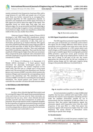
Accuracy of the circuit can be improved by using
electronic components with high precision and less
tolerance.
Previous work could also be useful for the effective and
reliable module implementation.
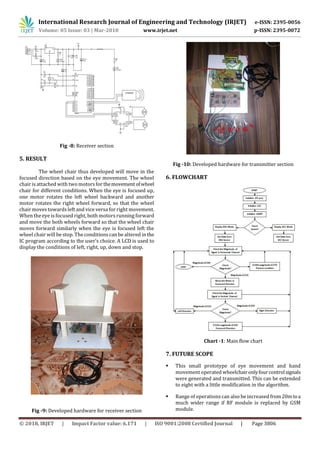
8. CONCLUSION
In this paper we propose the microcontroller based
wheel chair using EOG & accelerometer signals is
successfully implemented and demonstrated. The final
application of this wheel chair is it can be used in medical
application for paralyzed and handicapped people. Also by
using this signal we can control any real time machine like
computer system, robot, vehicle, wheelchair etc.
ACKNOWLEDGMENT
Thanks to Dr. A. B. Jirapure for his continuous
support. It was not possible to complete this work without
his proper guidance.
Thanksto our family that support usin variousfield
such as fund, idea and moral in completing the project.
The authors are very much thankful for the support
provided by the Department of Electronics
Telecommunication Engineering, RTMNU University,
Nagpur.
REFERENCES
[1] International Journal on Recent and Innovation Trends
in Computing and Communication ISSN: 2321-8169
Volume: 2 Issue: 6 1432 – 1436 “Novelapproachofman-
machine interaction using brain waves electric signals”.
[2] Úbeda A, Iáñez E, Azorín J (2011) “Wirelessandportable
eog-based interface for assisting disabled people”
Mechatronics, IEEE/ASMETransactionson16:870–873.
[3] IEEE transactions on neural systems and rehabilitation
engineering, vol. 10, no. 4, December 2002 209 “System
for assisted mobility using eye movements based on
electrooculography” Rafael Barea, Luciano Boquete,
Manuel Mazo, Member, IEEE, and Elena López.
[4] Michita Imai, Tetsuo Ono, and Hiroshi Ishiguro“Physical
relation and expressio: joint attention for human-robot
interaction”, August 2011.
[5] Barea R, Boquete L, Mazo M, López E (2002)
“Wheelchair guidance strategies using eog” Journal of
Intelligent and Robotic Systems 34: 279–299.
[6] E.J Rechy Ramirez, “Head movements based control of
an intelligent wheel chair in an indoor environment”,
IEEE International Conference on Roboticas and
Biometrics, pp. 1464-1469, Dec. 2012,doi: 10.1109/
ROBIO. 2012. 6491175.
[7] Sandeep, Supriya “Gesture controlled wheel-chair: A
review” IARJSET, volume 2, special issue 1, May 2015,
pp 23-27.
[8] Amundson JS, Amundson SG, “A joystick controlled
wheelchair”, Biomed Sci Instrum .1991; 27:131-3.
[9] O. Mirabella, M. Brischetto, G. Mastroeni “MEMS based
gesture recognition”, proc.HSI P.599 – 604, May 2010.
[10] V.Kumar,Vignesh S.N and Barathi Kannan K, “Head
motion controlled robotic wheelchair”, International
Journal of Emerging Technology and innovative
Engineering,vol.1,issue.3,March 2015,pp.176-179.](https://image.slidesharecdn.com/irjet-v5i3890-190206082218/85/IRJET-Microcontroller-Based-EOG-and-Accelerometer-Guide-Wheelchair-5-320.jpg)

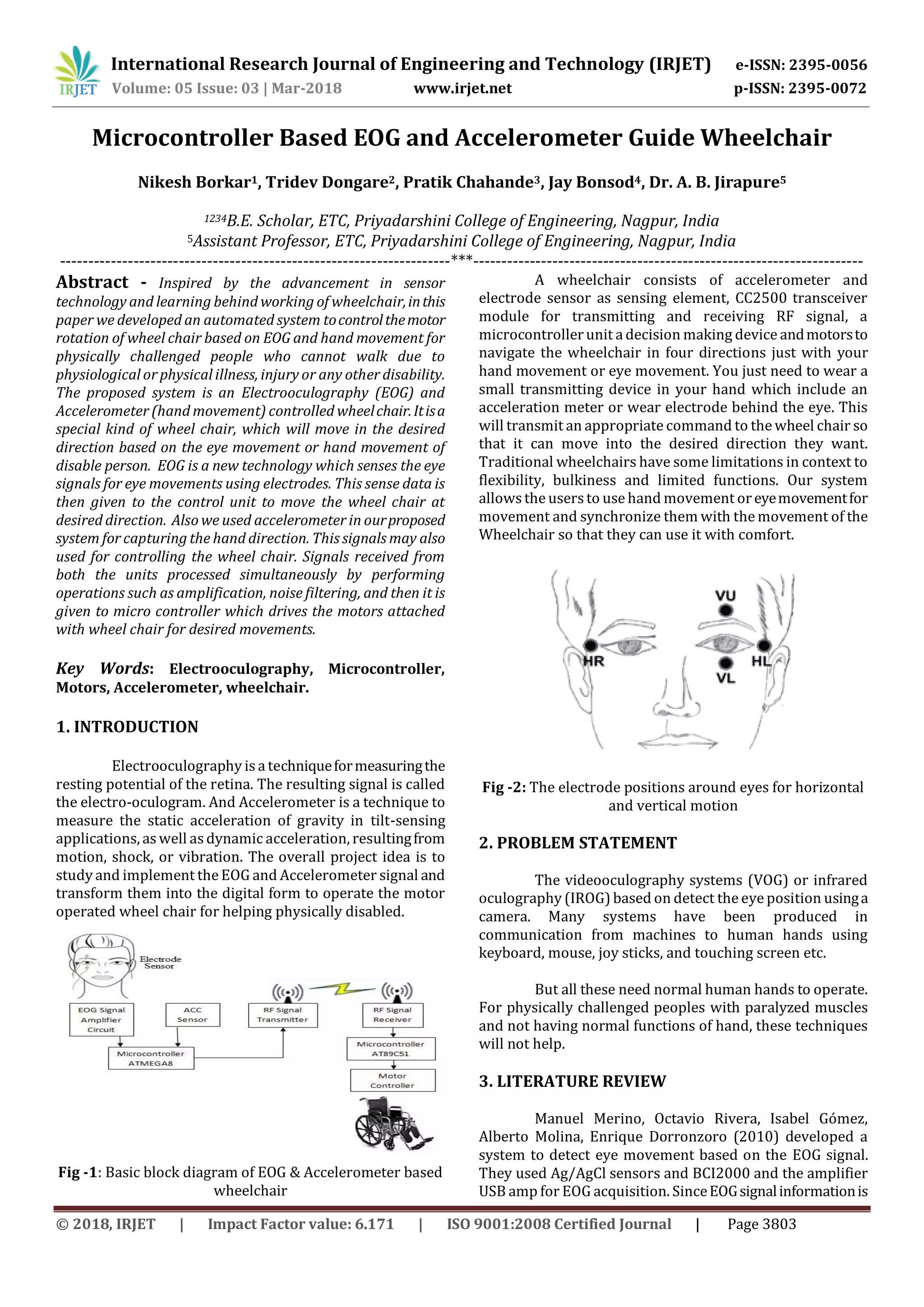
This document describes a microcontroller-based wheelchair system that can be controlled through either electrooculography (EOG) signals from eye movements or accelerometer signals from hand movements. EOG electrodes are placed near the eyes to detect eye movement signals, which are amplified and filtered before being sent to a microcontroller. An accelerometer on the hand detects movement signals. The microcontroller processes the signals and uses them to control motors that move the wheelchair in the desired direction based on eye or hand input. The system aims to help people with disabilities control a wheelchair independently using only their eyes or hands. It was developed using an ATmega8 microcontroller, CC2500 transceiver modules, EOG electrodes, an accelerometer