Download to read offline
![International Research Journal of Engineering and Technology (IRJET) e-ISSN: 2395-0056
Volume: 06 Issue: 04 | Apr 2019 www.irjet.net p-ISSN: 2395-0072
© 2019, IRJET | Impact Factor value: 7.211 | ISO 9001:2008 Certified Journal | Page 3417
Automatic Pneumatic Bumper Shock Absorber and Breaking System
Vishwajeet Godge1, Tushar Nagawade2, Nikhil Pawar3, Prashant Pawar4, Prof. M.D.Tayade5
1,2,3,4,5Department of Mechanical Engineering, Dhole Patil College of Engineering, Kharadi, Pune.
---------------------------------------------------------------------***----------------------------------------------------------------------
Abstract: In Today’s world Vehicle is used everywhere, so vehicle Accident is major problem.to avoid this we have developed
automatic impact reducing and speed minimizing technique in our project. This system is based upon electrically control system
called as “AUTOMATIC PNEUMATIC BUMPER SHOCK ABSORBER AND BREACKING SYSTEM”.
Automatic Bumper Shock Absorber system provides pre-crash safety to vehicle as well as improves response time of vehicle
breaking to keep safe distance between two vehicles. Therefore, our aim is to design and develop electronicallyoperatedbreaking
system which can automatically sense the object in front of vehicles and applies break automatically. This bumper may extractor
retract by using pneumatic system depends upon connection of pneumatic cylinder used. The ultrasonicsensorsensestheobstacle
closer to vehicle (within range 1.5m) and control signal are given to bumper activation and automatic breaking system which
control the speed, alerts the driver and reduces chances of accident.
Key Words: pre-crash safety, speed control, alert driver, reduce accident.
1. INTRODUCTION
India is the developing country and it is also densely populated country with maximum uses of vehicles.Thenumber ofpeople
expire during accident is very large as compare to other causes of death. Though there are different causes of accidents but
proper technology of breaking system and technology to reduce damage during accident should be developed. Hence there is
need to impact reducing system to prevent accident and damage to vehicle and driver. To achieve the goal, we design this
Automatic Pneumatic Bumper System. Our aim is to design and developautomaticcontrol systemintelligent electroniccontrol
automotive bumper activation system called “AUTOMATIC BUMPER SHOCK ABSORPTION”
In traffic vehicle has to move step by step very slowly. In this situation this system plays important role. It becomes very
necessary to driver to keep proper distance between two vehicles. By using system driver will directly get distance between
two vehicles on speedo meter in front of driver in digital form main aim is to design and develop a control system based on
electronic to control mechanical components for efficient and effective working. Thissystemconsistsofultrasonictransmitter
and receiver circuit, control unit, pneumatic bumper system and ultrasonic sensor.
Keywords: reduce damage, control unit, pneumatic system and ultra-sonic sensor.
2. LITERATURE REVIEW
A Literature review of the recently published research work on OptimizationofAutomaticPneumaticBumperShock Absorber
and Breaking System is carried out to Understand the research issues involved and presented here,
Mr. Umesh B. [1] A Characterization of Dynamic Human Braking Behavior with Implications for ACC Design: Skilled driving
behavior can be characterized as tracking, control, and regulation of appropriate perceptual cues. Be- cause of environmental
complexity, drivers must restrict attention to appropriate perceptual’ cues and act to cause their vehicle to beinanacceptable
perceptual state space. From experiments and supporting literature, we identify time head- way and time-to-collision as
plausible perceptual cues, and characterize skilled braking behavior as a trajectory through the resulting perceptual state
space. This trajectory, which terminates at a desired time headway value and infinite time to collision value, evolves in a
smooth counterclockwise direction in the perceptual space spanned by time headway and inverse time to collision.
Mr. Aayush Chawla, [2] A Deceleration Control Method of AutomobileforCollisionAvoidance:Driverassistancesystemssuch
as warning system and pre-crash safety system have been developed to reduce and mitigate crashesinroadtraffic.Intheview
point of preventive safety, deceleration assistance control is effective when collision risk is high and it is difficultforthedriver
to avoid it. On the other hand, driver can feel anxiety or nuisance against the system if the initiation timing of automatic brake
and/or deceleration profile is not appropriate and it may make the system inefficient. Thus, in order to realize an acceptable
and efficient system, it is important to know characteristics of comfortable deceleration behavior and apply them to
deceleration assistance system.](https://image.slidesharecdn.com/irjet-v6i4725-190709082713/85/IRJET-Automatic-Pneumatic-Bumper-Shock-Absorber-and-Breaking-System-1-320.jpg)
![International Research Journal of Engineering and Technology (IRJET) e-ISSN: 2395-0056
Volume: 06 Issue: 04 | Apr 2019 www.irjet.net p-ISSN: 2395-0072
© 2019, IRJET | Impact Factor value: 7.211 | ISO 9001:2008 Certified Journal | Page 3417
Automatic Pneumatic Bumper Shock Absorber and Breaking System
Vishwajeet Godge1, Tushar Nagawade2, Nikhil Pawar3, Prashant Pawar4, Prof. M.D.Tayade5
1,2,3,4,5Department of Mechanical Engineering, Dhole Patil College of Engineering, Kharadi, Pune.
---------------------------------------------------------------------***----------------------------------------------------------------------
Abstract: In Today’s world Vehicle is used everywhere, so vehicle Accident is major problem.to avoid this we have developed
automatic impact reducing and speed minimizing technique in our project. This system is based upon electrically control system
called as “AUTOMATIC PNEUMATIC BUMPER SHOCK ABSORBER AND BREACKING SYSTEM”.
Automatic Bumper Shock Absorber system provides pre-crash safety to vehicle as well as improves response time of vehicle
breaking to keep safe distance between two vehicles. Therefore, our aim is to design and develop electronicallyoperatedbreaking
system which can automatically sense the object in front of vehicles and applies break automatically. This bumper may extractor
retract by using pneumatic system depends upon connection of pneumatic cylinder used. The ultrasonicsensorsensestheobstacle
closer to vehicle (within range 1.5m) and control signal are given to bumper activation and automatic breaking system which
control the speed, alerts the driver and reduces chances of accident.
Key Words: pre-crash safety, speed control, alert driver, reduce accident.
1. INTRODUCTION
India is the developing country and it is also densely populated country with maximum uses of vehicles.Thenumber ofpeople
expire during accident is very large as compare to other causes of death. Though there are different causes of accidents but
proper technology of breaking system and technology to reduce damage during accident should be developed. Hence there is
need to impact reducing system to prevent accident and damage to vehicle and driver. To achieve the goal, we design this
Automatic Pneumatic Bumper System. Our aim is to design and developautomaticcontrol systemintelligent electroniccontrol
automotive bumper activation system called “AUTOMATIC BUMPER SHOCK ABSORPTION”
In traffic vehicle has to move step by step very slowly. In this situation this system plays important role. It becomes very
necessary to driver to keep proper distance between two vehicles. By using system driver will directly get distance between
two vehicles on speedo meter in front of driver in digital form main aim is to design and develop a control system based on
electronic to control mechanical components for efficient and effective working. Thissystemconsistsofultrasonictransmitter
and receiver circuit, control unit, pneumatic bumper system and ultrasonic sensor.
Keywords: reduce damage, control unit, pneumatic system and ultra-sonic sensor.
2. LITERATURE REVIEW
A Literature review of the recently published research work on OptimizationofAutomaticPneumaticBumperShock Absorber
and Breaking System is carried out to Understand the research issues involved and presented here,
Mr. Umesh B. [1] A Characterization of Dynamic Human Braking Behavior with Implications for ACC Design: Skilled driving
behavior can be characterized as tracking, control, and regulation of appropriate perceptual cues. Be- cause of environmental
complexity, drivers must restrict attention to appropriate perceptual’ cues and act to cause their vehicle to beinanacceptable
perceptual state space. From experiments and supporting literature, we identify time head- way and time-to-collision as
plausible perceptual cues, and characterize skilled braking behavior as a trajectory through the resulting perceptual state
space. This trajectory, which terminates at a desired time headway value and infinite time to collision value, evolves in a
smooth counterclockwise direction in the perceptual space spanned by time headway and inverse time to collision.
Mr. Aayush Chawla, [2] A Deceleration Control Method of AutomobileforCollisionAvoidance:Driverassistancesystemssuch
as warning system and pre-crash safety system have been developed to reduce and mitigate crashesinroadtraffic.Intheview
point of preventive safety, deceleration assistance control is effective when collision risk is high and it is difficultforthedriver
to avoid it. On the other hand, driver can feel anxiety or nuisance against the system if the initiation timing of automatic brake
and/or deceleration profile is not appropriate and it may make the system inefficient. Thus, in order to realize an acceptable
and efficient system, it is important to know characteristics of comfortable deceleration behavior and apply them to
deceleration assistance system.](https://image.slidesharecdn.com/irjet-v6i4725-190709082713/75/IRJET-Automatic-Pneumatic-Bumper-Shock-Absorber-and-Breaking-System-1-2048.jpg)
![International Research Journal of Engineering and Technology (IRJET) e-ISSN: 2395-0056
Volume: 06 Issue: 04 | Apr 2019 www.irjet.net p-ISSN: 2395-0072
© 2019, IRJET | Impact Factor value: 7.211 | ISO 9001:2008 Certified Journal | Page 3418
Mr. Srinivasan Chari, [3] Automatic Breaking with Pneumatic Bumper System: This system is assembled on four-wheeler
vehicle. Generally, this system consists of two mechanisms and these are automatic braking system and pneumatic bumper
system. Automatic braking system uses the infrared sensor (IR) which senses the vehicle which comes in front of our system
and which may be cause for accident. Then sensor gives feedback to engine through relay to stop the working of engine.
Mr. Aditya Gandhi, [4] Automobile vehicles have become integral part of our lives. With growing number of vehiclesonroad,
the numbers of traffic accidents are also increasing. It is important to prevent the chances of accidents and to protect the
passengers when accidents occur. Air bags provide safety, but they are costly. Safety, being a matter of primeimportance,can-
not be compromised for cost. Hence our attempt is to provide a reliable and safe system at low cost.Thoughtherearedifferent
causes for these accidents but proper technology of braking system and technology to reduce the damage (such as pneumatic
bumper system) during accident can be effective on the accident rates. So, in today’s world, implementation of proper
(automatic) braking system to prevent the accidents is a mustforvehicles.Therefore, pre-crashingsystemisdemanded.Sucha
system will prevent accidents on roads with poor visibility by using proximity sensors to detect other vehicles, or any other
obstacle in the path.
3. IMPORTANT COMPONENT
3.1 Pneumatic Cylinder:
The pneumatic cylinder used is double acting cylinder. The working fluid act alternatively on both side of piston. For
connecting rod to the piston with external mechanism holes are provided on the both side of the cylinder. Cylinder is
double acting cylinder which means that air pressure operates forward and backward strokes pneumatic cylinderisused
to carry out mechanical work.
3.2 Ultrasonic Sensor:
Ultrasonic sensor works on principle of SONAR & RADAR system which is used to determine distance of an object.
Ultrasonic sensor generates high frequency sound waves. When this sound wave hit the object, it reflects as an echo
which is sensed by receiver unit of some sensor.
3.2 Direction Control Valve:
A solenoid operated DCV is used in this system. The 2-way solenoid valves have one inlet & one outletport.Itcontrols
the direction of air flow to give motion to cylinder.
3.4 Control Valve:
The Arduino-Uno is a micro controller board based on the AT mega 328. It has 14 digital input/output pins (which 6
can be used as PWM outputs), 6analog input, 16 MHz ceramic resonator, USB Connections, power jack &reset button,
and digital display board is controlled by this microcontroller.
3.5 Air Compressor:
The air compressor used in car, the same compressor is used for this system.Thework producedbycompressorisnot
fully utilized in car. Just up to 40 to 45% is used & remaining is wasted. Hence the same compressor is used for this
system.](https://image.slidesharecdn.com/irjet-v6i4725-190709082713/85/IRJET-Automatic-Pneumatic-Bumper-Shock-Absorber-and-Breaking-System-2-320.jpg)
![International Research Journal of Engineering and Technology (IRJET) e-ISSN: 2395-0056
Volume: 06 Issue: 04 | Apr 2019 www.irjet.net p-ISSN: 2395-0072
© 2019, IRJET | Impact Factor value: 7.211 | ISO 9001:2008 Certified Journal | Page 3420
5. IMPORTANT CALCULATIONS
5.1 Stopping Distance Calculations,
The total stopping distance = Human perception distance human reaction distance + Breaking distance
+ Distance curved in 1msec
Breaking distance,
Dbreaking= V2 / 2µg
Where,
v=velocity before applying break
µ=coefficient of friction, µ=0.7
g=Acceleration due to Gravity, 9.81m/s
Dbreaking= (4.167)2/2*0.7*9.81 = 1.26m
Here, Human perception time=0, because it is automatic breaking system.
Total stopping Distance= 1.26+bumper actuation length
=1.26+0.100m
=1.36m
Hence the sensor range is set at 1.5meter.
5.2 Assumption regarding Vehicle (According to standards)
Weight of Vehicle=1500kg
Frictional coefficient of wheel=0.6
Wheel base=2meter
Center of Gravity of vehicles from ground=0.508m
Diameter of tire=0.5m
Inner Diameter of Disc (Di)=100mm
outer Diameter of Disc (Do)=200mm
5.3 Load distribution Analysis
40% of total load on front two tire
60% of total load on rear two tire
Load on each wheel,
On front wheel=300kg
On rear wheel=450kg
5.4 Breaking force & pressure analysis
Static load on wheel,
(Fs)=µf*Rn
=0.6*300*9.81
(Fs) =1765.8N
Dynamic Weight transfer,
(Fd)= [(m*a*h)/W]
= [(450*0.5*9.81*0.508)/2*2] …… {For a=0.5g}
(Fd) = 280.32N
Total Load,
FT =FS + Fd
=1765.8 + 280.32
FT =2046.12N.](https://image.slidesharecdn.com/irjet-v6i4725-190709082713/85/IRJET-Automatic-Pneumatic-Bumper-Shock-Absorber-and-Breaking-System-4-320.jpg)
![International Research Journal of Engineering and Technology (IRJET) e-ISSN: 2395-0056
Volume: 06 Issue: 04 | Apr 2019 www.irjet.net p-ISSN: 2395-0072
© 2019, IRJET | Impact Factor value: 7.211 | ISO 9001:2008 Certified Journal | Page 3421
Table -1: Total Load Analysis
5.5 Impact force calculations:
{Ref.: International Journal of Eng. Science and Computing, April 2017}
Velocity = 4.167 m/s
By equation of motion,
2as=v2-u2
Where, s= Breaking distance
v=Final velocity
u= Initial velocity
2*a*1.36=02-(4.167)2
a= 6.383 m/s2
Now,
Impact force, F= m*a
=1500*6.383
Impact force = 9574.5 N
Table -2: Impact Load Analysis
Sr. No Initial velocity (u) Acceleration (m/s2) Impact Force(N)
1 2 1.470 2205.88
2 4.167 6.383 9574.5
3 6.52 15.62 23443.23
6. CONCLUSIONS
1) Behind the designing of this system, our main aim is to improve the technique of prevention of accidents and also reducing
the hazard from accidents like damage of vehicle, injury of humans, etc.
2) In conclusion remarks of our project work; we have developed an “ACCIDENT PREVENTION SYSTEM BY AUTOMATIC
PNEUMATIC BUMPER” which helps to achieve low Impact damage.
REFERENCES
[1] Umesh B “DESIGN AND FABRICATION OF ANTI ROLL BACK SYSTEM IN VEHICLES USING DRUM & SHOE MECHANISM”
ISSN: 0976-1353 Volume 12 Issue 3 –JANUARY 2015.
[2] Aayush Chawla [2]systems for Commercial Vehicle systems India Pvt. Ltd. (KBI-CVs)” ANTIROLL BACK SYSTEM FOR
COMMERCIAL VEHICLES”
[3] Srinivasan Chari [3]“Pawl Motion in Free-Running Ratchet Gear at High Drum Speeds”, ISSN 1068-798X, Russian
Engineering Research, 2008, Vol. 28, No. 9, pp. 845–848.
[4] Aditya Gandhi All [4], “The Drum & Shoe Ring (RaPR) Mechanism”, 12th IFToMM World Congress, Besançon (France),
June18-21, 2007.
Sr. No Acceleration Dynamic Weight Transfer
(N)
Total Load
(N)
1 0.5 280.32 2046.12
2 1.2 672.76 2438.56
3 2.0 1121.28 2887.08
4 3.7 2074.37 3840.17](https://image.slidesharecdn.com/irjet-v6i4725-190709082713/85/IRJET-Automatic-Pneumatic-Bumper-Shock-Absorber-and-Breaking-System-5-320.jpg)
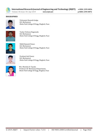

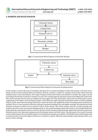
1. The document describes an automatic pneumatic bumper shock absorber and breaking system designed to improve vehicle safety. 2. The system uses an ultrasonic sensor to detect obstacles within 1.5 meters of the vehicle. If an obstacle is detected, the sensor sends a signal to activate the pneumatic bumper and automatically apply the brakes to slow the vehicle. 3. The pneumatic bumper is designed to retract and extend via a pneumatic cylinder to absorb impact forces and reduce damage in the event of a collision. The system is intended to improve response time during braking and control vehicle speed to reduce accident risks.


