Plano electrico 994 k cabina y chassis
•
0 likes•277 views

This document provides electrical schematic symbols, component location charts, and specifications for the 994K wheel loader. It includes over 100 symbols used on the schematics along with their definitions. Two charts show the location of over 110 components and 31 connectors on and within the machine. The document also lists specifications for switches, resistors, and senders used in the electrical system.

More Related Content
What's hot
What's hot (19)
Similar to Plano electrico 994 k cabina y chassis
Similar to Plano electrico 994 k cabina y chassis (20)
Recently uploaded
Recently uploaded (20)
Plano electrico 994 k cabina y chassis
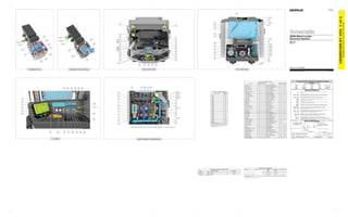
- 1. UENR5399-01 July 2017 Volume 1 of 3: Cab Wiring Printed in U.S.A. 994K Wheel Loader Electrical System MM91-UP MRK1-UP © 2017 Caterpillar, All Rights Reserved Pressure Symbol T Temperature Symbol Level Symbol Flow Symbol Circuit Breaker Symbol Harness and Wire Symbols Symbols Symbols and Definitions Harness And Wire Electrical Schematic Symbols Fuse: A component in an electrical circuit that will open the circuit if too much current flows through it. Switch (Normally Open): A switch that will close at a specified point (temp, press, etc.). The circle indicates that the component has screw terminals and a wire can be disconnected from it. Switch (Normally Closed): A switch that will open at a specified point (temp, press, etc.). No circle indicates that the wire cannot be disconnected from the component. Ground (Wired): This indicates that the component is connected to a grounded wire. The grounded wire is fastened to the machine. Ground (Case): This indicates that the component does not have a wire connected to ground. It is grounded by being fastened to the machine. Reed Switch: A switch whose contacts are controlled by a magnet. A magnet closes the contacts of a normally open reed switch; it opens the contacts of a normally closed reed switch. Sender: A component that is used with a temperature or pressure gauge. The sender measures the temperature or pressure. Its resistance changes to give an indication to the gauge of the temperature or pressure.T Relay (Magnetic Switch): A relay is an electrical component that is activated by electricity. It has a coil that makes an electromagnet when current flows through it. The electromagnet can open or close the switch part of the relay. Magnetic Latch Solenoid: A magnetic latch solenoid is an electrical component that is activated by electricity and held latched by a permanent magnet. It has two coils (latch and unlatch) that make electromagnet when current flows through them. It also has an internal switch that places the latch coil circuit open at the time the coil latches. Solenoid: A solenoid is an electrical component that is activated by electricity. It has a coil that makes an electromagnet when current flows through it. The electromagnet can open or close a valve or move a piece of metal that can do work. 1 2 AG-C4 111-7898 L-C12 3E-5179 9X-1123 Component Part Number Pin or Socket Number Part Number: for Connector Receptacle Part Number: for Connector Plug Harness Identification Letter(s): (A, B, C, ..., AA, AB, AC, ...) Plug 325-AG135 PK-14 Wire Color Wire Gauge Receptacle 1 1 2 2 Sure-Seal connector: Typical representation of a Sure-Seal connector. The plug and receptacle contain both pins and sockets. Deutsch connector: Typical representation of a Deutsch connector. The plug contains all sockets and the receptacle contains all pins. Fuse (5 Amps) 5A Harness identification code: This example indicates wire group 325, wire 135 in harness "AG". L-C12 3E-5179 Wire, Cable, or Harness Assembly Identification: Includes Harness Identification Letters and Harness Connector Serialization Codes (see sample). Harness Connector Serialization Code: The "C" stands for "Connector" and the number indicates which connector in the harness (C1, C2, C3, ...). UENR5399-01VOL1of3 42Page,(Dimensions:56inchesx35inches) CONN 1 CONN 6 CONN 8 CONN 9 CONN 10 CONN 12 CONN 15 CONN 11 CONN 2 CONN 3 CONN 19 CONN 4 CAB - REAR VIEWCAB - FRONT VIEW D - PANEL RIGHT CONSOLE - INTERIOR VIEW IMPLEMENT POD IMPLEMENT POD (JOYSTICK) CONN 5 CONN 13 CONN 25 CONN 24 CONN 16 CONN 17 CONN 30 CONN 18CONN 20 CONN 14 CONN 31 CONN 7 CONN 21 CONN 26 CONN 28 CONN 29 CONN 27 CONN 22 CONN 23 CONN 26 CONN 27 CONN 28 CONN 28 CONN 27 1 28 58 86 62 19 18 55 13 59 56 1036430 14 74 32 10 88 109 57 105 108 106 107 90 91 63 85 61 87 2 52 70 71 8 20 16 44 33 34 25 29 39 40 41 43 42 31 60 73 110 111 72 112 15 11 51 12 37 4546 47 48 50 3823 67 2468 69 3 4 7 5 21 22 35 6 54 65 98 99 100104 66 10195769284 81 17 79 93 94 82 80 75 77 83 78 89 96 102 97 27 36 9 264953 Component Schematic Location Machine Location Component Schematic Location Machine Location Alarm - Action F-4 1 Sensor - Louver Temperature H-3 58 Alarm - Machine Feature H-3 2 Sensor - Recirc Filter Temperature F-5 59 Block - Fuse B-10 3 Sensor - Temperature (HVAC Evaporator) G-16 60 Breaker - Engine ECM 1 C-11 4 Sensor - Third Lever Position I-3 61 Breaker - Engine ECM 2 C-11 5 Sensor - Throttle Position B-2 62 Breaker - Running Lamp C-11 6 Sensor - Tilt Lever Position I-3 63 Buss Bar C-11 7 Sensor - Torque Conv Pedal Position C-2 64 Control - Ethernet Switch (5 Port) E-4 8 Socket - 12V Aux Port 1 I-1 65 Control - Implement J-6 9 Socket - 12V Aux Port 2 I-1 66 Control - Joystick G-3 10 Strap As (Implement ECM) G-6 67 Control - Network Manager B-5 11 Strap As (Network Manager) A-5 68 Control - Transmission G-6 12 Strap As (Transmission ECM) D-6 69 Control As - Blower Fan Speed G-5 13 Suppressor - Arc 1 (Steel Mill) I-14 70 Control Gp - STIC J-3 14 Suppressor - Arc 2 (Steel Mill) I-14 71 Converter (Atch) H-11 15 Switch - AC Hi Low Pressure G-15 72 Converter (Std) H-12 16 Switch - AC Low Pressure G-15 73 Display - Information G-2 17 Switch - Armrest Position LH J-3 74 Display - Terrain J-9 18 Switch - ATC/Man I-1 75 Display - Vision C-15 19 Switch - Beacon G-1 76 Flasher (24V) A-3 20 Switch - Camera Sprayer E-1 77 Ground - Cab 1 B-9 21 Switch - Door B-2 78 Ground - Cab 2 B-9 22 Switch - Dual Wiper J-12 79 Ground - Implement ECM G-5 23 Switch - Forward Override I-15 80 Ground - Network Manager A-5 24 Switch - Front Flood H-1 81 Ground - Rear B-14 25 Switch - Front Intermittent Wiper I-12 82 Ground - Transmission ECM D-5 26 Switch - Hazard Lamp F-1 83 Keypad F-1 27 Switch - HID Lamp H-1 84 Module - Indication E-2 28 Switch - Horn I-3 85 Motor - Blower H-16 29 Switch - Ignition Key E-2 86 Motor - Front Wiper B-2 30 Switch - Implement Lockout I-4 87 Motor - Precleaner E-15 31 Switch - Implement Lockout (Joystick) G-3 88 Motor - Wiper LH E-15 32 Switch - Parking Brake D-3 89 Motor - Wiper Rear D-14 33 Switch - Payload Store I-3 90 Motor - Wiper RH F-15 34 Switch - Payload Store (Joystick) G-3 91 Panel - Fuse D-10 35 Switch - Rear Flood Lamp H-1 92 Panel - HVAC I-1 36 Switch - Rear Intermittent Wiper I-12 93 Product Link - Radio (Cell) B-6 37 Switch - Reverse Override I-15 94 Product Link - Radio (Sat) B-6 38 Switch - Running Lamp G-1 95 Pump - Door Washer LH F-15 39 Switch - Seat Belt Minder (Four Point) F-4 Pump - Door Washer RH F-15 40 Switch - Seat Belt Minder (Two Point) F-5 Pump - Front Washer F-15 41 Switch - Service Brake Pedal RH B-2 97 Pump - Rear Washer F-15 42 Switch - Service Lamp D-1 98 Pump - Sprayer Washer G-15 43 Switch - Shop Horn E-1 99 Radio G-12 44 Switch - Spot Lamp J-1 100 Relay - Horn 1 D-11 45 Switch - Starway Access G-1 101 Relay - Horn 2 D-11 46 Switch - Steering Lock J-3 102 Relay - Machine Power Distribution C-11 47 Switch - Stoplamp C-2 103 Relay - Main Power B-11 48 Switch - Third Function Lockout F-1 104 Relay - Steel Mill Backup Alarm I-16 49 Switch - Throttle Lock Set H-3 105 Resistor - CAN (Wireless) E-5 50 Switch - Throttle Lock Set/Resume H-3 106 Resistor - Pull-Up E-2 51 Switch - Throttle Lock Set/Resume (Joystick) F-3 107 Resistor (CAT Detect) C-15 52 Switch - Turn Signal H-4 108 Resistor (D-Panel) E-1 53 Switch - Turn Signal (Joystick) F-3 109 Resistor (Steel Mill) J-14 54 Switch - Washer Bottle Level E-15 110 Seat Gp - Air Suspension F-5 55 Thru Post B-12 111 Sensor - Arc Inclination D-2 56 Valve - Water G-16 112 Sensor - Lift Lever Position I-3 57 Volume 1 - Component Location 96 Connector Number Schematic Location CONN 1 I-16 CONN 2 D-15 CONN 3 G-15 CONN 4 H-15 CONN 5 H-15 CONN 6 J-14 CONN 7 I-14 CONN 8 H-14 CONN 9 F-14 CONN 10 E-14 CONN 11 D-14 CONN 12 B-14 CONN 13 B-14 CONN 14 A-14 CONN 15 A-14 CONN 16 I-11, J-12 CONN 17 J-12 CONN 18 I-12 CONN 19 I-12 CONN 20 H-12 CONN 21 H-10 CONN 22 H-10 CONN 23 G-10 CONN 24 A-6 CONN 25 A-6 CONN 26 I-5, G-5 CONN 27 I-5, G-5 CONN 28 I-5, G-5 CONN 29 J-5 CONN 30 I-3 CONN 31 Service Connector J-1 Volume 1 - Connector Location The connectors shown in this chart are for harness to harness connectors. Connectors that join a harness to a component are generally located at or near the component. See the Component Location Chart. Part No. Function Actuate Deactuate Contact Position 275 kPa MAX Low High 170 ± 55 kPa (39.88 psi MAX) (24.65 ± 7.97 psi) 2800 ± 140 kPa 1750 ± 200 kPa (406.1 ± 20.3 psi) (253.81 ± 29 psi) 103.4 ± 13.8 kPa 34.5 ± 7 kPa (14.99 ± 2 psi) (5 ± 1.01 psi) ¹ With increasing pressure the closed condition can be maintained up to 2800 kPa (405 psi), with decreasing pressure the closed condition can be maintained down to 170 kPa (25 psi). ² Contact position at the contacts of the harness connector. Off-Machine Switch Specification 149-6371 355-3148 AC High/Low Pressure 0-1 and 0-3 Normally Open 0-2 Normally Closed AC Low Pressure Normally Open Part No. Component Description Resistance (Ohms)¹ 134-2540 Resistor CAN - Wireless, D-Panel 120 ± 12 167-7801 Resistor Pull-Up 390 ± 19.5 174-3016 Resistor CAT Detect 120 ± 12 228-4982 Resistor Steel Mill 150 ± 7.5 ¹ At room temperature unless otherwise noted. Resistor, Sender and Solenoid Specifications
- 2. UENR5399-01VOL1of3 42Page,(Dimensions:56inchesx35inches) Components are shown installed on a fully operable machine with the key and engine off, transmission shifter in neutral and with parking brake set. Refer to the appropriate Service Manual for Troubleshooting, Specifications and Systems Operations. VOLUME 1 of 3: CAB WIRING SCHEMATIC PART NUMBER: 437-3826, CHANGE: 00, VERSION: - THIS SCHEMATIC IS FOR THE 994K WHEEL LOADER ELECTRICAL SYSTEM MEDIA NUMBER: UENR5399-01 Refer to the Parts Manual using a specific serial number prefix in SIS before ordering parts from this schematic. A B C D E F 1234567891011121314 G H I J A B C D E F G H I J 1516 12345678910111213141516 ABBREV RD WH OR YL PK BK GY PU BR GN BU COLOR RED WHITE ORANGE YELLOW PINK BLACK GRAY PURPLE BROWN GREEN BLUE SYMBOL DESCRIPTION BLADE, SPADE, RING OR SCREW TERMINAL CIRCUIT CONNECTED CIRCUIT NOT CONNECTED ELECTRICAL CONNECTION TO MACHINE STRUCTURE INTERNAL ELECTRICAL CONNECTION TO SURFACE OF COMPONENT CONNECTOR ATCH WIRE, CABLE, COMPONENT SPLICE CIRCUIT GROUPING DESIGNATIONH# WIRE GROUP COLOR DESCRIPTIONS GROUND CIRCUIT WIRES THAT HAVE SYSTEM VOLTAGE WHEN THE KEY SWITCH IS OFF WIRES THAT HAVE SYSTEM VOLTAGE WHEN THE KEY SWITCH IS ON VOLTAGE CONVERTER OUTPUT CIRCUIT STARTING CIRCUIT TRANSMISSION / ENGINE PUMP CONTROL CIRCUIT ENGINE CONTROL CIRCUIT HEATER AND AIR CONDITIONER CIRCUIT TURN SIGNAL / WIPER WASHER CIRCUIT CAT DATA LINK CAN DATA LINK RS-232 / RS-485 DATA LINK IMPLEMENT / VALVE / TOOL CONTROL CIRCUIT CAN DATA LINK A ETHERNET CAN DATA LINK D OTHER COLOR DESCRIPTIONS HIGHWAYS NOTE D: SHOWN FOR REFERENCE ONLY NOTE E: REFERENCE CHASSIS DIAGRAM SCHEMATIC P/N 420-4822 (990/844K) 420-4826 (994K) NOTE F: 10A FUSE 113-8490 15A FUSE 113-8491 20A FUSE 113-8492 15A BREAKER (MANUAL RESET) 280-2709 15A BREAKER (AUTO RESET) 180-0614 201-MC2 BK-16 F711-MC6 YL-18 F712-MC7 GN-18 201-MC13 BK-16 F711-MC6 YL-18 201-MC13 BK-16 201-MC2 BK-16 A272-MC42 BK-14 A272-MC42 BK-14 167-MC34 OR-14 A272-MC30 BK-14 A273-MC82 BK-18 A273-MC82 BK-18 202-MC60 BK-14 202-MC60 BK-14 202-MC62 BK-14 202-MC62 BK-14 170-MC65 RD-14 170-MC65 RD-14 170-MC69 RD-14 170-MC69 RD-14 167-MC32 OR-14 167-MC32 OR-14 146-MC366 GY-16 H717-MC29 BR-18 H717-MC29 BR-18 H713-MC37 PK-18 H713-MC37 PK-18 H714-MC38 OR-18 H714-MC38 OR-18 E921-MC39 PK-18 E921-MC39 PK-18 E921-MC39 PK-18 E922-MC40 GN-18 E922-MC40 GN-18 F743-MC43 GY-18 F743-MC43 GY-18 F742-MC44 PU-18 F742-MC44 PU-18 F745-MC45 YL-18 F745-MC45 YL-18 F744-MC46 BU-18 F744-MC46 BU-18 F744-MC46 BU-18 A771-MC51 PU-18 A771-MC51 PU-18 200-MC164 BK-14 E901-MC55 GN-18 E901-MC55 GN-18 E901-MC55 GN-18 E900-MC56 WH-18 E900-MC56 WH-18 E900-MC56 WH-18 E906-MC57 OR-18 E906-MC57 OR-18 E906-MC57 OR-18 E907-MC58 GY-18 E907-MC58 GY-18 E907-MC58 GY-18 E908-MC61 BR-18 E908-MC61 BR-18 E908-MC61 BR-18 755-MC73 OR-18 755-MC73 OR-18 755-MC73 OR-18 J807-MC74 BK-18 J807-MC74 BK-18 J807-MC74 BK-18 900-MC75 PU-18 900-MC75 PU-18 900-MC75 PU-18 J809-MC78 BK-18 J809-MC78 BK-18 J809-MC78 BK-18 752-MC79 YL-18 752-MC79 YL-18 752-MC79 YL-18 751-MC80 GN-18 751-MC80 GN-18 751-MC80 GN-18 754-MC81 BU-18 754-MC81 BU-18 754-MC81 BU-18 J842-MC71 BK-18 J842-MC71 BK-18 K983-MC70 BU-18 K983-MC70 BU-18 H717-MC29 BR-18 A771-MC51 PU-18 H713-MC37 PK-18 H714-MC38 OR-18 E921-MC39 PK-18 E922-MC40 GN-18 F743-MC43 GY-18 F742-MC44 PU-18 F745-MC45 YL-18 F744-MC46 BU-18 E908-MC61 BR-18 E907-MC58 GY-18 E906-MC57 OR-18 E900-MC56 WH-18 E901-MC55 GN-18 K983-MC70 BU-18 J842-MC71 BK-18 755-MC73 OR-18 J807-MC74 BK-18 900-MC75 PU-18 J809-MC78 BK-18 751-MC80 GN-18 754-MC81 BU-18 202-MC83 BK-14 893-MC139 GN-18 892-MC140 BR-18 892-MC138 BR-18 892-MC138 BR-18 893-MC137 GN-18 893-MC137 GN-18 H718-MC204 GY-18 H718-MC204 GY-18 H718-MC204 GY-18 M912-MC208 BU-18 M912-MC208 BU-18 M912-MC208 BU-18 C461-MC206 OR-18 C461-MC206 OR-18 C461-MC206 OR-18 125-MC16 OR-18 125-MC16 OR-18 156-MC155 YL-14 616-MC25 BU-16 146-MC366 GY-16 118-MC110 GY-16 118-MC110 GY-16 118-MC112 GY-16 118-MC112 GY-16 118-MC113 GY-16 118-MC113 GY-16 118-MC111 GY-16 118-MC111 GY-16 200-MC118 BK-18 200-MC118 BK-18 200-MC114 BK-18 200-MC114 BK-18 118-MC364 GY-14 118-MC364 GY-14 118-MC364 GY-14 525-MC124 GY-16 525-MC124 GY-16 525-MC124 GY-16 523-MC125 BR-16 523-MC125 BR-16 523-MC125 BR-16 527-MC126 GN-16 527-MC126 GN-16 527-MC126 GN-16 524-MC123 BU-16 524-MC123 BU-16 524-MC123 BU-16 505-MC119 BU-16 505-MC119 BU-16 505-MC119 BU-16 504-MC120 YL-16 504-MC120 YL-16 504-MC120 YL-16 503-MC121 BR-16 503-MC121 BR-16 503-MC121 BR-16 507-MC122 WH-18 507-MC122 WH-18 507-MC122 WH-18 528-MC127 PK-16 528-MC127 PK-16 528-MC127 PK-16 526-MC128 YL-16 526-MC128 YL-16 526-MC128 YL-16 529-MC129 WH-18 529-MC129 WH-18 529-MC129 WH-18 502-MC130 OR-16 502-MC130 OR-16 502-MC130 OR-16 501-MC131 GN-16 501-MC131 GN-16 501-MC131 GN-16 500-MC132 BR-16 500-MC132 BR-16 500-MC132 BR-16 118-MC134 GY-16 118-MC134 GY-16 506-MC133 PU-18506-MC133 PU-18 506-MC133 PU-18 129-MC214 RD-14 210-MC387 BK-14 120-MC390 YL-16 120-MC390 YL-16 120-MC389 YL-16 592-MC386 BU-14 592-MC386 BU-14 592-MC385 BU-16 200-MC384 BK-14 200-MC384 BK-14 508-MC393 PU-18 508-MC393 PU-18 509-MC394 WH-18 509-MC394 WH-18 511-MC395 BR-18 511-MC395 BR-18 512-MC396 GN-18 512-MC396 GN-18 299-MC197 BK-18 E918-MC222 GN-18 E917-MC192 WH-18 A272-MC41 BK-14 A272-MC41 BK-14 CONNECT TO C-C1 VOL 2, LOC G-5 ON THE CHASSIS SCHEMATIC NOTE E 299-MC212 BK-18 299-MC212 BK-18 299-MC212 BK-18 146-MC221 GY-16 146-MC221 GY-16 146-MC215 GY-18 146-MC215 GY-18 164-MC225 WH-16 450-MC230 YL-16 450-MC230 YL-16 450-MC230 YL-16 450-MC230 YL-16 451-MC231 BR-16 451-MC231 BR-16 451-MC231 BR-16 451-MC231 BR-16 A273-MC232 BK-18 A273-MC232 BK-18 A273-MC233 BK-18 A273-MC233 BK-18 E909-MC235 WH-18 E909-MC235 WH-18 E909-MC235 WH-18 E909-MC235 WH-18 801-MC248 PK-18 801-MC248 PK-18 801-MC248 PK-18 801-MC248 PK-18 G747-MC250 OR-18 G747-MC250 OR-18 G747-MC250 OR-18 G747-MC250 OR-18 H724-MC249 YL-18 H724-MC249 YL-18 H724-MC249 YL-18 H724-MC249 YL-18 J808-MC251 BK-18 J808-MC251 BK-18 J808-MC251 BK-18 J808-MC251 BK-18 752-MC79 YL-18 C532-MC254 GN-18 C532-MC254 GN-18 C532-MC254 GN-18 C532-MC254 GN-18 E705-MC255 BU-18 E705-MC255 BU-18 E705-MC255 BU-18 E705-MC255 BU-18 T750-MC162 BR-18 T750-MC162 BR-18 T750-MC162 BR-18 T750-MC162 BR-18 E985-MC270 BR-18 E985-MC270 BR-18 E985-MC270 BR-18 E985-MC270 BR-18 A273-MC272 BK-18 A273-MC272 BK-18 A273-MC272 BK-18 F417-MC202 YL-18 161-MC97 PK-16 A629-MC345 BU-14 201-MC346 BK-16 201-MC346 BK-16 123-MC348 RD-16 113-MC349 OR-16 113-MC349 OR-16 113-MC349 OR-16 129-MC351 RD-14 102-MC354 RD-14 102-MC353 RD-14 102-CP1 RD-16 604-CP2 OR-16 102-MC352 RD-14 102-MC352 RD-14 116-MC358 BR-14 116-MC358 BR-14 116-MC358 BR-14 102-MC357 RD-12 114-MC372 RD-18 114-MC372 RD-18 210-MC383 BK-16 602-MC335 WH-18 210-MC387 BK-14 105-MC398 RD-14 105-MC398 RD-14 105-MC398 RD-14 892-MC402 BR-18 892-MC402 BR-18 892-MC402 BR-18 893-MC401 GN-18 893-MC401 GN-18 893-MC401 GN-18 641-MC407 OR-16 623-MC409 BU-16 622-MC408 PU-16 604-MC412 OR-16 604-MC412 OR-16 A700-MC414 OR-16 A700-MC414 OR-16 998-MC416 BR-18 998-MC416 BR-18 F702-MC417 GN-16 F702-MC417 GN-16 F702-MC417 GN-16 998-MC420 BR-18 998-MC420 BR-18 998-MC200 BR-18 998-MC200 BR-18 C978-MC418 BR-18 C978-MC418 BR-18 C979-MC419 OR-18 C979-MC419 OR-18 Y757-MC425 BU-18 Y757-MC425 BU-18 Y756-MC424 GY-18 Y756-MC424 GY-18 998-MC423 BR-18 998-MC426 BR-18 998-MC426 BR-18 F721-MC427 GY-16 F721-MC427 GY-16 F722-MC428 OR-16 F722-MC428 OR-16 201-MC429 BK-16 201-MC429 BK-16 108-MC435 BU-14 108-MC435 BU-14 108-MC435 BU-14 200-MC436 BK-14 200-MC456 BK-16 118-MC455 GY-16 118-MC455 GY-16 502-MC130 OR-16 110-MC457 RD-16 110-MC457 RD-16 110-MC457 RD-16 638-MC460 WH-16 603-MC461 PK-16 125-MC467 OR-16 125-MC467 OR-16 M931-MC470 YL-18 H711-MC512 GN-18 H710-MC516 PK-18 H722-MC473 GN-18 H722-MC473 GN-18 H722-MC473 GN-18 J842-MC474 BK-18 J842-MC474 BK-18 J842-MC474 BK-18 607-MC478 PK-14 119-MC488 PK-16 119-MC488 PK-16 119-MC488 PK-16 609-MC495 YL-14 609-MC495 YL-14 164-MC497 WH-18 164-MC497 WH-18 164-MC497 WH-18 592-MC450 BU-16 102-MC525 RD-14 102-MC525 RD-14 102-MC525 RD-14 T909-MC468 YL-18 T909-MC468 YL-18 T909-MC468 YL-18 T909-MC468 YL-18 T908-MC370 BU-18 T908-MC370 BU-18 T908-MC370 BU-18 T908-MC370 BU-18 142-MC521 BU-18 142-MC521 BU-18 148-MC522 RD-18 148-MC522 RD-18 120-MC391 YL-16 122-MC491 BU-14 120-MC415 YL-16 200-MC413 BK-14 200-MC413 BK-14 105-MC374 RD-14 A513-MC363 PK-16 ATCH 10 AMP V CONV FOR COMM RADIO 168-MC1 GN-16 168-MC1 GN-16 893-MC361 GN-16 119-MC463 PK-16 119-MC463 PK-16 119-MC463 PK-16 119-MC463 PK-16 102-MC485 RD-14 146-MC366 GY-16 119-MC463 PK-16 119-MC488 PK-16 123-MC88 RD-16 201-MC346 BK-16 102-MC353 RD-14 102-MC525 RD-14 129-MC351 RD-14 113-MC349 OR-16 114-MC372 RD-18 105-MC398 RD-14 102-MC352 RD-14 116-MC358 BR-14 118-MC364 GY-14 102-MC354 RD-14 201-MC429 BK-16 164-MC497 WH-18 122-MC491 BU-14 110-MC457 RD-16 102-MC357 RD-12 120-MC391 YL-16 120-MC391 YL-16 120-MC391 YL-16 892-MC404 BR-18 998-MC426 BR-18 F721-MC427 GY-16 F722-MC428 OR-16 998-MC416 BR-18 123-MC348 RD-16 502-MC130 OR-16 501-MC131 GN-16 500-MC132 BR-16 118-MC134 GY-16 201-MC346 BK-16 102-MC352 RD-14 893-MC403 GN-18 892-MC404 BR-18 A700-MC414 OR-16 114-MC372 RD-18 604-MC412 OR-16 F702-MC417 GN-16 H722-MC473 GN-18 681-MC152 OR-14 102-MC354 RD-14 129-MC351 RD-14 122-MC491 BU-14 638-MC460 WH-16 102-MC353 RD-14 609-MC495 YL-14 A624-MC375 WH-16 J842-MC474 BK-18 H722-MC473 GN-18 J842-MC474 BK-18 A273-MC272 BK-18 892-MC402 BR-18 893-MC401 GN-18 A272-MC52 BK-14 892-MC404 BR-18 893-MC403 GN-18 681-MC152 OR-14 130-MC28 RD-14 103-CC1 RD-0 142-MC521 BU-18 148-MC522 RD-18 523-MC125 BR-16 525-MC124 GY-16 506-MC133 PU-18 119-MC463 PK-16 529-MC129 WH-18 527-MC126 GN-16 528-MC127 PK-16 526-MC128 YL-16 524-MC123 BU-16 507-MC122 WH-18 F721-MC427 GY-16 F722-MC428 OR-16 623-MC409 BU-16 622-MC408 PU-16 C979-MC419 OR-18 C978-MC418 BR-18 604-MC412 OR-16 Y756-MC424 GY-18 592-MC450 BU-16 F702-MC417 GN-16 A700-MC414 OR-16 Y757-MC425 BU-18 603-MC461 PK-16 638-MC460 WH-16 609-MC495 YL-14 998-MC423 BR-18 998-MC416 BR-18 998-MC426 BR-18 113-MC349 OR-16 161-MC97 PK-16 105-MC398 RD-14 146-MC215 GY-18 201-MC429 BK-16 118-MC364 GY-14 119-MC463 PK-16 110-MC457 RD-16 119-MC488 PK-16 607-MC478 PK-14 164-MC497 WH-18 102-MC525 RD-14 A629-MC345 BU-14 A771-MC51 PU-18 H717-MC29 BR-18 H713-MC37 PK-18 F744-MC46 BU-18 H714-MC38 OR-18 F745-MC45 YL-18 F742-MC44 PU-18 E921-MC39 PK-18 F743-MC43 GY-18 M912-MC208 BU-18 E922-MC40 GN-18 299-MC212 BK-18 C461-MC206 OR-18 H718-MC204 GY-18 J842-MC71 BK-18 K983-MC70 BU-18 E901-MC55 GN-18 752-MC79 YL-18 E908-MC61 BR-18 751-MC80 GN-18 C532-MC254 GN-18 754-MC81 BU-18 E705-MC255 BU-18 E906-MC57 OR-18 755-MC73 OR-18 801-MC248 PK-18 J809-MC78 BK-18 451-MC231 BR-16 900-MC75 PU-18 450-MC230 YL-16 H724-MC249 YL-18 E909-MC235 WH-18 A273-MC272 BK-18 E900-MC56 WH-18 893-MC401 GN-18 E985-MC270 BR-18 J808-MC251 BK-18 J807-MC74 BK-18 G747-MC250 OR-18 T908-MC370 BU-18 T909-MC468 YL-18 T750-MC162 BR-18 E907-MC58 GY-18 892-MC402 BR-18 170-MC371 RD-14 164-MC225 WH-16 167-MC53 OR-14 118-MC134 GY-16 500-MC132 BR-16 501-MC131 GN-16 502-MC130 OR-16 500-MC132 BR-16 502-MC130 OR-16 592-MC380 BU-14 118-MC110 GY-16 118-MC112 GY-16 118-MC113 GY-16 118-MC111 GY-16 200-MC114 BK-18 200-MC118 BK-18 505-MC119 BU-16 504-MC120 YL-16 503-MC121 BR-16 200-MC456 BK-16 M912-MC208 BU-18 H711-MC512 GN-18 H710-MC516 PK-18 F743-MC43 GY-18 H714-MC38 OR-18 H713-MC37 PK-18 E918-MC222 GN-18 E917-MC192 WH-18 892-MC140 BR-18 893-MC139 GN-18 146-MC366 GY-16 E901-MC55 GN-18 E906-MC57 OR-18 754-MC81 BU-18 J809-MC78 BK-18 K983-MC70 BU-18 E985-MC270 BR-18 E909-MC235 WH-18 E908-MC61 BR-18 900-MC75 PU-18 J808-MC251 BK-18 J807-MC74 BK-18 T750-MC162 BR-18 751-MC80 GN-18 451-MC231 BR-16 J842-MC71 BK-18 755-MC73 OR-18 752-MC79 YL-18 G747-MC250 OR-18 H724-MC249 YL-18 801-MC248 PK-18 E705-MC255 BU-18 C532-MC254 GN-18 E900-MC56 WH-18 E907-MC58 GY-18 450-MC230 YL-16 T909-MC468 YL-18 T908-MC370 BU-18 H711-MC512 GN-18 H710-MC516 PK-18 E918-MC222 GN-18 E917-MC192 WH-18 C461-MC206 OR-18 998-MC200 BR-18 C978-MC418 BR-18 123-MC348 RD-16 998-MC426 BR-18 998-MC416 BR-18 F702-MC417 GN-16 118-MC134 GY-16 502-MC130 OR-16 638-MC460 WH-16 500-MC132 BR-16 622-MC408 PU-16 622-MC408 PU-16 622-MC408 PU-16 623-MC409 BU-16 501-MC131 GN-16 603-MC461 PK-16 F722-MC428 OR-16 108-MC435 BU-14 F721-MC427 GY-16 604-MC412 OR-16 641-MC407 OR-16 167-MC34 OR-14 167-MC32 OR-14 170-MC69 RD-14 170-MC65 RD-14 170-MC69 RD-14 122-MC491 BU-14 603-MC461 PK-16 638-MC460 WH-16 F722-MC428 OR-16 F721-MC427 GY-16 604-MC412 OR-16 A700-MC414 OR-16 114-MC372 RD-18 116-MC358 BR-14 102-MC352 RD-14 102-MC353 RD-14 102-MC354 RD-14 129-MC351 RD-14 500-MC132 BR-16 E922-MC40 GN-18 F742-MC44 PU-18 F745-MC45 YL-18 C461-MC206 OR-18 H717-MC29 BR-18 A771-MC51 PU-18 H718-MC204 GY-18 A272-MC30 BK-14 641-MC407 OR-16 C979-MC419 OR-18 609-MC495 YL-14 170-MC65 RD-14 167-MC32 OR-14 167-MC34 OR-14 501-MC131 GN-16 299-MC212 BK-18 M912-MC208 BU-18 H718-MC204 GY-18 H717-MC29 BR-18 A771-MC51 PU-18 F744-MC46 BU-18 H714-MC38 OR-18 E921-MC39 PK-18 E922-MC40 GN-18 F745-MC45 YL-18 F742-MC44 PU-18 F743-MC43 GY-18 H713-MC37 PK-18 641-MC407 OR-16 C978-MC418 BR-18 C979-MC419 OR-18 998-MC426 BR-18 998-MC416 BR-18 F702-MC417 GN-16 118-MC134 GY-16 502-MC130 OR-16 638-MC460 WH-16 501-MC131 GN-16 500-MC132 BR-16 604-MC412 OR-16 F722-MC428 OR-16 A700-MC414 OR-16 F721-MC427 GY-16 603-MC461 PK-16 609-MC495 YL-14 501-MC131 GN-16 892-MC404 BR-18 892-MC404 BR-18 893-MC403 GN-18 893-MC403 GN-18 893-MC403 GN-18 607-MC478 PK-14 167-MC34 OR-14 H722-MC473 GN-18 H722-MC473 GN-18 J842-MC474 BK-18 200-MC164 BK-14 200-MC392 BK-16 200-MC392 BK-16 G729-MC465 OR-18 G729-MC465 OR-18 G729-MC465 OR-18 G729-MC465 OR-18 G729-MC465 OR-18 G729-MC465 OR-18 E797-MC480 WH-18 E797-MC480 WH-18 E797-MC480 WH-18 E797-MC480 WH-18 E797-MC480 WH-18 E797-MC480 WH-18 H716-MC484 WH-18 H716-MC484 WH-18 H716-MC484 WH-18 H716-MC484 WH-18 H716-MC484 WH-18 H716-MC484 WH-18 M739-MC446 YL-18 M739-MC446 YL-18 M739-MC446 YL-18 M739-MC446 YL-18 M739-MC446 YL-18 M739-MC446 YL-18 R799-MC471 BR-18 R799-MC471 BR-18 R799-MC471 BR-18 R799-MC471 BR-18 R799-MC471 BR-18 R799-MC471 BR-18 592-MC380 BU-14 A700-MC414 OR-16 200-MC164 BK-14 998-MC200 BR-18 210-MC383 BK-16 120-MC389 YL-16 A513-MC363 PK-16 592-MC385 BU-16 102-MC485 RD-14 156-MC154 YL-14 156-MC154 YL-14 A624-MC375 WH-16 A624-MC375 WH-16 A624-MC375 WH-16 A624-MC375 WH-16 161-MC97 PK-16 161-MC97 PK-16 161-MC97 PK-16 129-MC333 RD-14 129-MC333 RD-14 681-MC152 OR-14 A629-MC345 BU-14 A629-MC345 BU-14 A629-MC345 BU-14 A629-MC345 BU-14 130-MC28 RD-14 200-MC164 BK-14 616-MC25 BU-16 616-MC25 BU-16 616-MC25 BU-16 607-MC478 PK-14 607-MC478 PK-14 607-MC478 PK-14 623-MC409 BU-16 641-MC407 OR-16 622-MC408 PU-16 C978-MC418 BR-18 998-MC200 BR-18 C979-MC419 OR-18 299-MC197 BK-18 892-MC513 BR-16 623-MC409 BU-16 M905-MC458 WH-18 M905-MC458 WH-18 M905-MC458 WH-18 M905-MC458 WH-18 M905-MC458 WH-18 M905-MC458 WH-18 M904-MC182 OR-18 M904-MC182 OR-18 M904-MC182 OR-18 M904-MC182 OR-18 M904-MC182 OR-18 M904-MC182 OR-18 112-CJ1 PU-4 105-MC374 RD-14 102-MC357 RD-12 186-MC538 RD-14 186-MC538 RD-14 186-MC538 RD-14 186-MC538 RD-14 186-MC538 RD-14 186-MC538 RD-14 186-MC538 RD-14 110-MC457 RD-16 140-MC224 BU-16 140-MC224 BU-16 614-MC360 PU-16 614-MC360 PU-16 614-MC360 PU-16 614-MC360 PU-16 614-MC360 PU-16 614-MC337 PU-16 614-MC337 PU-16 614-MC337 PU-16 614-MC337 PU-16 614-MC337 PU-16 614-MC496 PU-16 614-MC496 PU-16 614-MC496 PU-16 614-MC496 PU-16 614-MC496 PU-16 614-MC496 PU-16 164-MC445 WH-18 321-MC494 BR-18 321-MC494 BR-18 144-MC304 GN-14 144-MC304 GN-14 E575-MC487 BU-18 E575-MC487 BU-18 E575-MC487 BU-18 U733-MC448 WH-14 U733-MC448 WH-14 U733-MC448 WH-14 317-MC507 YL-14 322-MC441 GY-14 322-MC441 GY-14 322-MC441 GY-14 P990-MC104 BR-18 P990-MC104 BR-18 P990-MC104 BR-18 P990-MC104 BR-18 P990-MC104 BR-18 641-MC407 OR-16 623-MC409 BU-16 144-MC105 GN-14 144-MC365 GN-14 144-MC365 GN-14 144-MC365 GN-14 119-MC183 PK-14 119-MC183 PK-14 201-MC482 BK-16 140-MC84 BU-16 140-MC84 BU-16 140-MC84 BU-16 140-MC84 BU-16 140-MC84 BU-16 893-MC361 GN-16 892-MC513 BR-16 F417-MC202 YL-18 200-MC180 BK-16 200-MC180 BK-16 410-MC171 WH-18 200-MC397 BK-18 200-MC397 BK-18 200-MC378 BK-16 200-MC378 BK-16 184-MC481 RD-14 184-MC481 RD-14 184-MC481 RD-14 184-MC481 RD-14 184-MC481 RD-14 184-MC481 RD-14 184-MC481 RD-14 148-MC522 RD-18 142-MC521 BU-18 202-MC432 BK-14 A272-MC400 BK-14 184-MC481 RD-14 A513-MC363 PK-16 186-CV1 RD-14 186-CV1 RD-14 120-CV10 YL-16 120-CV10 YL-16 120-CV2 YL-16 120-CV2 YL-16 186-CV1 RD-14 120-CV4 YL-16 120-CV4 YL-16 120-CV7 YL-16 120-CV7 YL-16 200-CV3 BK-14 200-CV3 BK-14 200-CV6 BK-14 200-CV6 BK-14 200-CV9 BK-14 200-CV9 BK-14 200-CV11 BK-14 200-CV11 BK-14 E555-CV12 OR-14 E555-CV12 OR-14 E555-CV5 OR-14 E555-CV5 OR-14 E555-CV8 OR-14 E555-CV8 OR-14 616-MC25 BU-16 602-MC335 WH-18 299-MC201 BK-18 299-MC201 BK-18 201-MC532 BK-16 201-MC532 BK-16 200-MC499 BK-14 200-MC499 BK-14 200-MC499 BK-14 200-MC499 BK-14 200-MC499 BK-14 626-MC199 BU-16 626-MC199 BU-16 626-MC199 BU-16 626-MC199 BU-16 626-MC199 BU-16 626-MC399 BU-16 626-MC399 BU-16 VIMS TELEMETRY (REFERENCE ONLY) 201-MC535 BK-18 201-MC535 BK-18 201-MC535 BK-18 CONNECT TO C-C2 VOL 2, LOC E-5 ON THE CHASSIS SCHEMATIC NOTE E CONNECT TO C-C3 VOL 2, LOC C-5 ON THE CHASSIS SCHEMATIC NOTE E CONNECT TO C-C4 VOL 2, LOC B-5 ON THE CHASSIS SCHEMATIC NOTE E 875-AF5 BU-16 875-AF4 BU-16 875-AF3 BU-16 876-AF6 OR-16 876-AF2 OR-16 E972-AF1 BU-16 200-MC436 BK-14 876-AF7 OR-16 120-MC391 YL-16 120-MC389 YL-16 120-MC415 YL-16 120-MC390 YL-16 G749-MC66 YL-18 G749-MC66 YL-18 G749-MC66 YL-18 G748-MC67 PU-18 G748-MC67 PU-18 G748-MC67 PU-18 G768-MC239 GN-18 G768-MC239 GN-18 G768-MC239 GN-18 G760-MC240 WH-18 G760-MC240 WH-18 G760-MC240 WH-18 G761-MC241 YL-18 G761-MC241 YL-18 G761-MC241 YL-18 G762-MC242 BR-18 G762-MC242 BR-18 G762-MC242 BR-18 G763-MC243 PU-18 G763-MC243 PU-18 G763-MC243 PU-18 G755-MC238 GY-18 G755-MC238 GY-18 G755-MC238 GY-18 G750-MC237 BU-18 G750-MC237 BU-18 G750-MC237 BU-18 A273-MC77 BK-18 A273-MC77 BK-18 616-MC477 BU-14 616-MC477 BU-14 616-MC477 BU-14 616-MC477 BU-14 616-MC477 BU-14 616-MC477 BU-14 122-MC491 BU-14 615-MC603 YL-14 615-MC603 YL-14 615-MC603 YL-14 646-MC476 OR-16 646-MC476 OR-16 646-MC476 OR-16 608-MC479 GN-14 608-MC479 GN-14 608-MC479 GN-14 608-MC479 GN-14 608-MC479 GN-14 608-MC479 GN-14 651-MC486 PK-14 651-MC486 PK-14 651-MC486 PK-14 651-MC486 PK-14 651-MC486 PK-14 651-MC486 PK-14 299-MC159 BK-18 299-MC159 BK-18 C530-MC115 BU-18 C530-MC115 BU-18 299-MC147 BK-18 299-MC147 BK-18 120-MC415 YL-16 998-MC423 BR-18 Y756-MC424 GY-18 Y757-MC425 BU-18 998-MC423 BR-18 Y756-MC424 GY-18 Y757-MC425 BU-18 998-MC423 BR-18 Y756-MC424 GY-18 998-MC423 BR-18 Y756-MC424 GY-18 Y757-MC425 BU-18 BULB 305-5629 F712-MC220 GN-18 F712-MC220 GN-18 F712-MC220 GN-18 F711-MC209 YL-18 F711-MC209 YL-18 F711-MC209 YL-18 201-MC482 BK-16 F712-MC7 GN-18 603-MC461 PK-16 614-MC179 PU-16 C540-MC156 GY-16 592-MC388 BU-16 592-MC388 BU-16 592-MC388 BU-16 592-MC388 BU-16 308-MC466 YL-14 326-MC109 RD-16 326-MC109 RD-16 326-MC265 RD-16 326-MC265 RD-16 326-MC265 RD-16 307-MC508 OR-14 307-MC508 OR-14 307-MC508 OR-14 307-MC508 OR-14 105-MC107 RD-14 105-MC107 RD-14 105-MC107 RD-14 105-MC107 RD-14145-MC151 BU-14 145-MC151 BU-14 145-MC151 BU-14 145-MC151 BU-14 156-MC155 YL-14 156-MC150 YL-14 156-MC150 YL-14 156-MC150 YL-14 156-MC150 YL-14 616-MC174 BU-14 608-MC157 GN-14 A624-MC186 WH-16 F711-MC462 YL-18 F712-MC492 GN-18 634-MC356 WH-16 634-MC356 WH-16 634-MC356 WH-16 614-MC93 PU-16 614-MC93 PU-16 626-MC89 BU-16 308-MC466 YL-14 326-MC265 RD-16 592-MC388 BU-16 156-RA104 YL-14 145-RA103 BU-14 893-RA122 GN-16 892-RA108 BR-16 616-RA105 BU-14 608-RA107 GN-14 603-RA106 PK-16 144-RA102 GN-14 626-RA72 BU-16 626-RA72 BU-16 614-RA71 PU-16 626-RA1 BU-16 ELECTRONIC TECHNICIAN SERVICE TOOL CONNECTOR 626-RA1 BU-16 102-RA115 RD-14 102-RA87 RD-14 651-RA89 PK-14 129-RA90 RD-14 129-RA91 RD-14 641-RA92 OR-16 116-RA93 BR-14 681-RA94 OR-14 638-RA95 WH-16 122-RA96 BU-14 623-RA97 BU-16 609-RA98 YL-14 646-RA99 OR-16 622-RA100 PU-16 A624-RA109 WH-16 614-RA141 PU-16 614-RA137 PU-16 614-RA151 PU-16 614-RA137 PU-16 610-RA138 OR-14 614-RA139 PU-16 614-RA140 PU-16 614-RA143 PU-16 626-RA131 BU-16 626-RA131 BU-16 X800-RA15 OR-18 X800-RA15 OR-18 X800-RA15 OR-18 E529-RA118 YL-18 E529-RA118 YL-18 X998-RA30 BR-18 X998-RA30 BR-18 X998-RA30 BR-18 A524-RA119 BR-18 A524-RA119 BR-18 C540-RA29 GY-16 C540-RA29 GY-16 C540-RA29 GY-16 C539-RA12 YL-16 125-RA6 OR-16 125-RA6 OR-16 614-RA74 PU-16 614-RA74 PU-16 614-RA73 PU-16 614-RA73 PU-16 123-RA121 RD-16 614-RA150 PU-16 144-RA153 GN-16 144-RA101 GN-16 634-RA120 WH-16 634-RA120 WH-16 614-RA144 PU-16 614-RA144 PU-16 626-RA156 BU-16 626-RA136 BU-16 626-RA82 BU-16 626-RA83 BU-16 626-RA84 BU-16 626-RA85 BU-16 626-RA86 BU-16 119-R14 PK-16 119-R14 PK-16 119-R18 PK-16 119-R18 PK-16 200-R15 BK-14 200-R15 BK-14 200-R10 BK-14 200-R10 BK-14 200-R9 BK-18 200-R9 BK-18 200-R43 BK-18 200-R43 BK-18 200-R6 BK-18 200-R6 BK-18 200-R4 BK-18 200-R4 BK-18 529-R7 WH-18 529-R7 WH-18 529-R8 WH-18 529-R8 WH-18 529-R38 WH-18 529-R38 WH-18 119-R37 PK-16 524-R16 BU-16 524-R16 BU-16 524-R16 BU-16 523-R44 BR-16 523-R44 BR-16 523-R44 BR-16 525-R17 GY-16 525-R17 GY-16 525-R17 GY-16 527-R12 GN-16 527-R12 GN-16 527-R12 GN-16 528-R13 PK-16 528-R13 PK-16 528-R13 PK-16 526-R11 YL-16 526-R11 YL-16 526-R11 YL-16 507-R5 WH-18 507-R5 WH-18 507-R5 WH-18 506-R3 PU-18 506-R3 PU-18 506-R3 PU-18 299-R19 BK-18 299-R19 BK-18 E731-R1 BR-18 E731-R1 BR-18 E731-R1 BR-18 A557-R25 WH-14 A557-R25 WH-14 A557-R25 WH-14 200-R24 BK-14 200-R24 BK-14 142-R52 BU-18 142-R52 BU-18 142-R52 BU-18 651-R53 PK-14 651-R53 PK-14 651-R53 PK-14 615-R54 YL-14 615-R54 YL-14 615-R54 YL-14 200-R49 BK-14 200-R49 BK-14 R970-R39 YL-18 R970-R39 YL-18 140-R55 BU-16 140-R55 BU-16 140-R55 BU-16 200-R57 BK-16 200-R57 BK-16 200-R59 BK-14 200-R59 BK-14 C542-R60 GN-16 C542-R60 GN-16 C542-R60 GN-16 A629-R62 BU-14 A629-R62 BU-14 A629-R62 BU-14 R976-R42 GN-18 R976-R42 GN-18 161-R45 PK-16 603-R47 PK-16 603-R47 PK-16 603-R47 PK-16 638-R28 WH-16 638-R28 WH-16 638-R28 WH-16 148-R31 RD-18 148-R31 RD-18 148-R31 RD-18 200-R32 BK-14 200-R32 BK-14 200-R48 BK-14 200-R48 BK-14 161-R45 PK-16 200-R35 BK-12 200-R35 BK-12 200-R41 BK-12 200-R41 BK-12 200-R46 BK-14 161-R45 PK-16 NOTE E CHASSIS SCHEMATIC VOL 2 (LOC I-16) ON THE CONNECT TO W-C1 119-R37 PK-16 NOTE D E529-RA118 YL-18 A524-RA119 BR-18 122-RA96 BU-14 623-RA97 BU-16 609-RA98 YL-14 646-RA99 OR-16 622-RA100 PU-16 129-RA91 RD-14 144-RA102 GN-14 145-RA103 BU-14 156-RA104 YL-14 616-RA105 BU-14 603-RA106 PK-16 608-RA107 GN-14 892-RA108 BR-16 A624-RA109 WH-16 641-RA92 OR-16 116-RA93 BR-14 681-RA94 OR-14 102-RA115 RD-14 102-RA87 RD-14 651-RA89 PK-14 129-RA90 RD-14 638-RA95 WH-16 123-RA121 RD-16 893-RA122 GN-16 F712-RA123 GN-18 F711-RA124 YL-18 144-RA101 GN-16 614-RA71 PU-16 634-RA120 WH-16 614-RA143 PU-16 610-RA138 OR-14 614-RA140 PU-16 614-RA141 PU-16 626-RA82 BU-16 614-RA151 PU-16 626-RA136 BU-16 626-RA83 BU-16 626-RA84 BU-16 626-RA85 BU-16 626-RA86 BU-16 144-RA153 GN-16 156-RA104 YL-14 145-RA103 BU-14 608-RA107 GN-14 681-RA94 OR-14 129-RA91 RD-14 616-RA105 BU-14 646-RA99 OR-16 129-RA90 RD-14 116-RA93 BR-14 A624-RA109 WH-16 123-RA121 RD-16 893-RA122 GN-16 F712-RA123 GN-18 F711-RA124 YL-18 892-RA108 BR-16 609-RA98 YL-14 603-RA106 PK-16 623-RA97 BU-16 651-RA89 PK-14 122-RA96 BU-14 622-RA100 PU-16 638-RA95 WH-16 102-RA115 RD-14 102-RA87 RD-14 641-RA92 OR-16 201-RA127 BK-16 E554-MC144 PK-18 E554-MC144 PK-18 E554-MC144 PK-18 E554-MC144 PK-18 E554-MC144 PK-18 E554-MC144 PK-18 P990-MC143 BR-18 P990-MC143 BR-18 626-MC89 BU-16 614-MC179 PU-16 F711-MC462 YL-18 F712-MC492 GN-18 893-MC361 GN-16 638-MC460 WH-16 651-MC486 PK-14 102-MC353 RD-14 102-MC354 RD-14 681-MC152 OR-14 116-MC358 BR-14 A624-MC186 WH-16 892-MC513 BR-16 608-MC157 GN-14 603-MC461 PK-16 616-MC174 BU-14 156-MC150 YL-14 145-MC151 BU-14 144-MC365 GN-14 129-MC351 RD-14 622-MC408 PU-16 646-MC476 OR-16 609-MC495 YL-14 623-MC409 BU-16 122-MC491 BU-14 A524-MC377 BR-18 105-MC107 RD-14 892-MC404 BR-18 893-MC403 GN-18 892-MC513 BR-16 892-MC513 BR-16 892-MC513 BR-16 893-MC361 GN-16 893-MC361 GN-16 893-MC361 GN-16 210-MC95 BK-16 210-MC95 BK-16 317-MC507 YL-14 317-MC507 YL-14 614-RA139 PU-16 614-RA150 PU-16 626-RA156 BU-16 210-MC95 BK-16 210-MC95 BK-16 210-MC95 BK-16 210-MC95 BK-16 210-MC178 BK-16 210-MC178 BK-16 103-EF1 RD-6 326-MC265 RD-16 308-MC466 YL-14 592-MC388 BU-16 C539-MC236 YL-16 X998-MC341 BR-18 C540-MC156 GY-16 200-R46 BK-14 REAR HARNESS REAR HARNESS D-PANEL HARNESS D-PANEL HARNESS 125-MC16 OR-18 125-MC16 OR-18 K983-MC76 BU-18 K983-MC76 BU-18 J842-MC36 BK-18 J842-MC36 BK-18 K983-MC475 BU-18 K983-MC475 BU-18 K983-MC475 BU-18 E456-MC5 WH-18 E456-MC5 WH-18 E456-MC5 WH-18 E456-MC5 WH-18 E456-MC5 WH-18 E456-MC5 WH-18 168-MC103 GN-16 123-MC100 RD-16 123-MC100 RD-16 123-MC100 RD-16 123-MC100 RD-16 123-MC100 RD-16 STOPLAMP SW C539-RA12 YL-16 GROUND K977-MC27 PK-18 K977-MC27 PK-18 K977-MC27 PK-18 K977-MC27 PK-18 K977-MC27 PK-18 K977-MC27 PK-18 167-MC3 OR-14 167-MC3 OR-14 167-MC3 OR-14 167-MC3 OR-14 (67) STRAP AS F417-MC202 YL-18 M931-MC574 YL-18 G952-MC4 WH-18 G952-MC4 WH-18 G952-MC4 WH-18 C530-MC115 BU-18 C530-MC115 BU-18 C530-MC115 BU-18 C530-MC115 BU-18 J764-MC540 BR-18 J764-MC540 BR-18 J764-MC540 BR-18 J764-MC540 BR-18 J764-MC540 BR-18 J764-MC540 BR-18 A485-MC544 BU-18 A485-MC544 BU-18 A485-MC544 BU-18 A485-MC544 BU-18 A485-MC544 BU-18 A485-MC544 BU-18 A275-MC116 BK-18 A275-MC116 BK-18 A275-MC116 BK-18 K833-MC546 PK-18 K833-MC546 PK-18 K833-MC546 PK-18 K833-MC546 PK-18 K833-MC546 PK-18 K833-MC546 PK-18 R970-MC149 YL-18 R976-MC161 GN-18 R970-MC153 YL-18 R970-MC153 YL-18 R976-MC163 GN-18 R976-MC163 GN-18 R970-MC149 YL-18 R976-MC161 GN-18 125-MC16 OR-18 125-MC16 OR-18 168-MC103 GN-16 125-MC21 OR-18 125-MC21 OR-18 125-MC21 OR-18 125-MC21 OR-18 125-MC21 OR-18 125-MC21 OR-18 893-MC293 GN-18 892-MC294 BR-18 201-MC296 BK-16 F711-MC315 YL-18 308-MC291 YL-16 308-MC291 YL-16 308-MC291 YL-16 308-MC291 YL-16 201-MC296 BK-16 201-MC296 BK-16 1400-RA20 WH-18 1400-RA20 WH-18 1400-RA20 WH-18 1401-RA22 GN-18 1401-RA22 GN-18 1401-RA22 GN-18 1402-RA23 BR-18 1402-RA23 BR-18 1402-RA23 BR-18 1403-RA24 BU-18 1403-RA24 BU-18 1403-RA24 BU-18 141-MC313 PK-16 141-MC313 PK-16 141-MC313 PK-16 R970-MC299 YL-18 R970-MC299 YL-18 R970-MC299 YL-18 R970-MC299 YL-18 R970-MC299 YL-18 893-MC293 GN-18 892-MC294 BR-18 R976-MC303 GN-18 R976-MC303 GN-18 R976-MC303 GN-18 R976-MC303 GN-18 R976-MC303 GN-18 443-MC326 YL-18 496-MC327 WH-18 C453-MC331 YL-18 446-MC332 PU-18 C491-MC367 PU-18 499-MC368 GY-18 417-MC453 GY-18 C462-MC489 PK-18 C456-MC501 OR-18 C457-MC502 BU-18 429-MC515 YL-18 C529-MC533 GY-18 341-MC547 BU-18 P739-MC550 BU-18 447-MC555 PK-18 C454-MC556 GN-18 G444-MC557 BU-18 C455-MC560 PU-18 424-MC561 GY-18 G438-MC562 PK-18 RR CAB GND STUD 239-HV17 BK-12 X944-HV2 BU-12 159-R2 BU-16 159-R2 BU-16 159-R2 BU-16 159-MC567 BU-16 159-MC567 BU-16 159-MC567 BU-16 159-MC567 BU-16 159-MC567 BU-16 159-MC567 BU-16 A526-R22 PK-18 A526-R22 PK-18 A526-R22 PK-18 124-MC568 GN-12 124-MC568 GN-12 124-MC568 GN-12 299-R33 BK-18 299-R33 BK-18 299-R30 BK-18 299-MC569 BK-18 299-MC569 BK-18 299-MC570 BK-16 C539-RA12 YL-16 626-RA5 BU-16 C554-R34 PK-18 C554-R34 PK-18 C554-R34 PK-18 A557-MC571 WH-14 A557-MC571 WH-14 A557-MC571 WH-14 A557-MC571 WH-14 A557-MC571 WH-14 A557-MC571 WH-14 200-R36 BK-14 200-R36 BK-14 A275-MC116 BK-18 A275-MC116 BK-18 299-MC570 BK-16 299-MC570 BK-16 299-MC569 BK-18 299-MC569 BK-18 299-MC569 BK-18 A526-MC158 PK-18 A526-MC158 PK-18 A526-MC158 PK-18 A526-MC158 PK-18 A526-MC158 PK-18 A526-MC158 PK-18 C584-MC438 WH-18 C554-MC443 PK-18 C554-MC443 PK-18 C554-MC443 PK-18 C554-MC443 PK-18 C554-MC443 PK-18 C554-MC443 PK-18 E558-MC572 YL-18 E558-MC572 YL-18 C552-MC573 WH-18 M931-MC574 YL-18 M931-MC470 YL-18 513-MC577 OR-18 513-MC577 OR-18 513-MC577 OR-18 513-MC577 OR-18 513-MC577 OR-18 X800-MC579 OR-18 X800-MC579 OR-18 X800-MC579 OR-18 X800-MC338 OR-18 E529-MC439 YL-18 E529-MC439 YL-18 E529-MC439 YL-18 E529-MC439 YL-18 A524-MC377 BR-18 A524-MC377 BR-18 A524-MC377 BR-18 X998-MC341 BR-18 X998-MC341 BR-18 X998-MC381 BR-18 C540-MC156 GY-16 C540-MC156 GY-16 C539-MC236 YL-16 C539-MC236 YL-16 C539-MC236 YL-16 170-MC108 RD-14 170-MC108 RD-14 170-MC108 RD-14 170-MC108 RD-14 202-MC379 BK-14 202-MC379 BK-14 (69) STRAP AS 138-MC523 GN-16 138-MC523 GN-16 138-MC523 GN-16 138-MC523 GN-16 138-MC523 GN-16 138-MC523 GN-16 E569-MC580 WH-18 E569-MC580 WH-18 E569-MC580 WH-18 E569-MC580 WH-18 E569-MC580 WH-18 E569-MC580 WH-18 447-MC555 PK-18 447-MC555 PK-18 447-MC555 PK-18 447-MC555 PK-18 447-MC555 PK-18 443-MC326 YL-18 443-MC326 YL-18 443-MC326 YL-18 443-MC326 YL-18 443-MC326 YL-18 429-MC515 YL-18 429-MC515 YL-18 429-MC515 YL-18 429-MC515 YL-18 429-MC515 YL-18 446-MC332 PU-18 446-MC332 PU-18 446-MC332 PU-18 446-MC332 PU-18 446-MC332 PU-18 424-MC561 GY-18 424-MC561 GY-18 424-MC561 GY-18 424-MC561 GY-18 424-MC561 GY-18 G438-MC562 PK-18 G438-MC562 PK-18 G438-MC562 PK-18 G438-MC562 PK-18 G438-MC562 PK-18 P739-MC550 BU-18 P739-MC550 BU-18 P739-MC550 BU-18 P739-MC550 BU-18 P739-MC550 BU-18 144-MC304 GN-14 164-MC445 WH-18 164-MC445 WH-18 E575-MC487 BU-18 P989-MC584 GN-16 P989-MC584 GN-16 P989-MC584 GN-16 P989-MC584 GN-16 P989-MC584 GN-16 P989-MC584 GN-16 P990-MC585 BR-16 P990-MC585 BR-16 P990-MC585 BR-16 P990-MC585 BR-16 P990-MC585 BR-16 P990-MC585 BR-16 626-MC587 BU-16 H479-MC590 OR-18 H479-MC590 OR-18 H479-MC590 OR-18 H479-MC590 OR-18 H479-MC590 OR-18 H479-MC590 OR-18 186-MC538 RD-14 167-MC53 OR-14 170-MC371 RD-14 123-MC88 RD-16 200-MC483 BK-16 200-MC483 BK-16 200-MC596 BK-14 200-MC596 BK-14 200-MC594 BK-16 200-MC594 BK-16 200-MC593 BK-18 200-MC593 BK-18 SW B+ USB 144-MC105 GN-14 626-RA5 BU-16 626-MC587 BU-16 626-MC587 BU-16 626-MC587 BU-16 626-MC587 BU-16 626-MC587 BU-16 146-MC215 GY-18 146-MC215 GY-18 321-MC494 BR-18 610-MC600 OR-14 610-MC600 OR-14 610-RA138 OR-14 610-MC602 OR-14 610-MC602 OR-14 610-MC602 OR-14 610-MC602 OR-14 610-MC602 OR-14 610-MC602 OR-14 681-MC152 OR-14 681-MC152 OR-14 681-MC152 OR-14 646-MC476 OR-16 646-MC476 OR-16 615-MC603 YL-14 615-MC603 YL-14 615-MC603 YL-14 145-MC151 BU-14 322-MC441 GY-14 322-MC441 GY-14 322-MC441 GY-14 E789-MC437 PU-16 E789-MC437 PU-16 130-MC28 RD-14 129-MC214 RD-14 185-MC117 YL-16 185-MC117 YL-16 185-MC117 YL-16 185-MC117 YL-16 185-MC117 YL-16 185-RA2 YL-16 185-RA2 YL-16 201-RA3 BK-16 201-RA31 BK-16 201-RA31 BK-16 200-MC68 BK-16 200-MC68 BK-16 K960-RA8 YL-18 K960-RA8 YL-18 K961-RA9 GN-18 K961-RA9 GN-18 201-MC296 BK-16 893-MC293 GN-18 892-MC294 BR-18 F711-MC315 YL-18 F712-MC316 GN-18 R970-MC149 YL-18 R970-MC153 YL-18 R976-MC161 GN-18 R976-MC163 GN-18 U733-MC448 WH-14 U733-MC448 WH-14 U733-MC448 WH-14 U733-MC448 WH-14 317-MC507 YL-14 317-MC507 YL-14 317-MC507 YL-14 317-MC507 YL-14 161-MC97 PK-16 E558-MC572 YL-18 E558-MC572 YL-18 E558-MC572 YL-18 E558-MC572 YL-18 E558-MC572 YL-18 299-MC228 BK-18 299-MC228 BK-18 299-MC228 BK-18 299-MC228 BK-18 299-MC228 BK-18 299-MC228 BK-18 C552-MC573 WH-18 C552-MC573 WH-18 299-MC245 BK-14 299-MC247 BK-18 124-MC568 GN-12 C584-MC438 WH-18 299-MC247 BK-18 200-MC257 BK-12 200-MC257 BK-12 200-MC257 BK-12 200-MC257 BK-12 X944-R26 BU-12 X944-R26 BU-12 X944-R26 BU-12 239-R27 BK-12 239-R27 BK-12 239-R27 BK-12 239-MC260 BK-12 239-MC260 BK-12 239-MC260 BK-12 239-MC260 BK-12 239-MC260 BK-12 239-MC260 BK-12 337-MC261 WH-16 337-MC261 WH-16 337-MC261 WH-16 998-MC262 BR-18 998-MC262 BR-18 Y995-MC263 GY-16 Y995-MC263 GY-16 Y995-MC263 GY-16 102-MC264 RD-14 326-MC265 RD-16 326-MC266 RD-16 326-MC266 RD-16 A893-MC275 OR-16 A893-MC275 OR-16 A893-MC275 OR-16 A744-MC279 GN-16 A744-MC279 GN-16 A744-MC279 GN-16 G444-MC557 BU-18 G444-MC557 BU-18 G444-MC557 BU-18 G444-MC557 BU-18 G444-MC557 BU-18 G445-MC47 GY-18 G445-MC47 GY-18 G445-MC47 GY-18 G445-MC47 GY-18 G445-MC47 GY-18 G445-MC47 GY-18 C451-MC49 YL-18 C451-MC49 YL-18 C451-MC49 YL-18 C451-MC49 YL-18 C451-MC49 YL-18 C451-MC49 YL-18 C493-MC216 WH-18 C493-MC216 WH-18 C493-MC216 WH-18 C493-MC216 WH-18 C493-MC216 WH-18 C493-MC216 WH-18 H408-MC280 GN-18 H408-MC280 GN-18 H408-MC280 GN-18 H408-MC280 GN-18 H408-MC280 GN-18 H408-MC280 GN-18 C529-MC533 GY-18 C529-MC533 GY-18 C529-MC533 GY-18 C529-MC533 GY-18 C529-MC533 GY-18 499-MC368 GY-18 499-MC368 GY-18 499-MC368 GY-18 499-MC368 GY-18 499-MC368 GY-18 G454-MC295 PK-18 G454-MC295 PK-18 G454-MC295 PK-18 G454-MC295 PK-18 G454-MC295 PK-18 G454-MC295 PK-18 H411-MC301 YL-18 H411-MC301 YL-18 H411-MC301 YL-18 H411-MC301 YL-18 H411-MC301 YL-18 H411-MC301 YL-18 417-MC453 GY-18 417-MC453 GY-18 417-MC453 GY-18 417-MC453 GY-18 417-MC453 GY-18 C455-MC560 PU-18 C455-MC560 PU-18 C455-MC560 PU-18 C455-MC560 PU-18 C455-MC560 PU-18 C454-MC556 GN-18 C454-MC556 GN-18 C454-MC556 GN-18 C454-MC556 GN-18 C454-MC556 GN-18 G477-MC344 GY-18 G477-MC344 GY-18 G477-MC344 GY-18 G477-MC344 GY-18 G477-MC344 GY-18 G477-MC344 GY-18 C456-MC501 OR-18 C456-MC501 OR-18 C456-MC501 OR-18 C456-MC501 OR-18 C456-MC501 OR-18 C457-MC502 BU-18 C457-MC502 BU-18 C457-MC502 BU-18 C457-MC502 BU-18 C457-MC502 BU-18 C453-MC331 YL-18 C453-MC331 YL-18 C453-MC331 YL-18 C453-MC331 YL-18 C453-MC331 YL-18 HVAC 201-RA127 BK-16 F711-MC315 YL-18 F712-MC316 GN-18 F711-RA10 YL-18 F711-RA10 YL-18 F712-RA13 GN-18 F712-RA13 GN-18 K961-RA18 GN-18 K961-RA18 GN-18 K960-RA17 YL-18 K960-RA17 YL-18 F712-RA27 GN-18 F712-RA27 GN-18 F711-RA26 YL-18 F711-RA26 YL-18 201-RA3 BK-16 299-R30 BK-18 E731-MC616 BR-18 E731-MC616 BR-18 E731-MC616 BR-18 E731-MC616 BR-18 E731-MC616 BR-18 E731-MC616 BR-18 164-MC35 WH-18 164-MC35 WH-18 164-MC35 WH-18 321-MC494 BR-18 321-MC494 BR-18 321-MC494 BR-18 321-MC494 BR-18 174-MC87 RD-16 174-MC87 RD-16 141-MC313 PK-16 141-MC313 PK-16 141-MC313 PK-16 168-MC146 GN-16 168-MC146 GN-16 168-MC146 GN-16 168-MC146 GN-16 168-MC146 GN-16 326-MC266 RD-16 326-MC266 RD-16 326-MC266 RD-16 326-MC266 RD-16 A893-MC275 OR-16 A893-MC275 OR-16 A893-MC275 OR-16 A893-MC275 OR-16 A744-MC279 GN-16 A744-MC279 GN-16 A744-MC279 GN-16 A744-MC279 GN-16 337-MC261 WH-16 337-MC261 WH-16 337-MC261 WH-16 337-MC261 WH-16 998-MC262 BR-18 998-MC262 BR-18 998-MC262 BR-18 998-MC262 BR-18 Y995-MC263 GY-16 Y995-MC263 GY-16 Y995-MC263 GY-16 Y995-MC263 GY-16 102-MC264 RD-14 102-MC264 RD-14 123-MC348 RD-16 F711-MC209 YL-18 F712-MC220 GN-18 F712-MC229 GN-18 F712-MC229 GN-18 F711-MC226 YL-18 F711-MC226 YL-18 F712-MC316 GN-18 P990-MC283 BR-16 P990-MC283 BR-16 P990-MC283 BR-16 135-CH1 BU-4 X800-MC338 OR-18X800-MC340 OR-18 X800-MC340 OR-18 X800-MC340 OR-18 X800-MC340 OR-18 X800-MC340 OR-18 X998-MC381 BR-18X998-MC421 BR-18 X998-MC421 BR-18 X998-MC421 BR-18 X998-MC421 BR-18 X998-MC421 BR-18 306-MC422 GN-16 306-MC422 GN-16 306-MC422 GN-16 306-MC422 GN-16 306-MC422 GN-16 306-MC422 GN-16 X721-MC430 BR-16 X721-MC430 BR-16 X721-MC430 BR-16 X721-MC430 BR-16 X721-MC430 BR-16 X721-MC430 BR-16 F711-MC226 YL-18 F712-MC229 GN-18 F711-MC431 YL-18 F711-MC431 YL-18 F711-MC431 YL-18 F711-MC431 YL-18 F711-MC431 YL-18 F712-MC433 GN-18 F712-MC433 GN-18 F712-MC433 GN-18 F712-MC433 GN-18 F712-MC433 GN-18 308-MC466 YL-14 125-MC54 OR-16 125-MC54 OR-16 125-MC54 OR-16 125-MC54 OR-16 125-MC54 OR-16 125-MC54 OR-16 E789-MC437 PU-16 P990-MC283 BR-16 P990-MC283 BR-16 P990-MC283 BR-16 R970-MC442 YL-18 R976-MC449 GN-18 614-RA46 PU-16 614-RA46 PU-16 626-RA47 BU-16 626-RA47 BU-16 140-RA48 BU-16 140-RA48 BU-16 140-RA48 BU-16 140-MC464 BU-16 140-MC464 BU-16 140-MC464 BU-16 140-MC464 BU-16 140-MC464 BU-16 578-RA49 BU-16 578-RA49 BU-16 578-RA49 BU-16578-MC469 BU-16 578-MC469 BU-16 578-MC469 BU-16 578-MC469 BU-16 578-MC469 BU-16 578-MC469 BU-16 578-MC469 BU-16 592-MC386 BU-14 592-MC385 BU-16 200-MC384 BK-14 200-MC413 BK-14 210-MC387 BK-14 210-MC383 BK-16 201-MC493 BK-16 201-MC493 BK-16 140-MC504 BU-16 140-MC504 BU-16 140-MC504 BU-16 140-MC504 BU-16 140-MC504 BU-16 134-MC510 YL-16 134-MC510 YL-16 134-MC510 YL-16 134-MC510 YL-16 134-MC510 YL-16 134-MC510 YL-16 892-MC524 BR-18 892-MC524 BR-18 892-MC524 BR-18 892-MC524 BR-18 892-MC524 BR-18 893-MC528 GN-18 893-MC528 GN-18 893-MC528 GN-18 893-MC528 GN-18 893-MC528 GN-18 (ON CHASSIS) CAT DETECT DISPLAY 140-CA3 BU-16 140-CA3 BU-16 140-CA3 BU-16 134-CA4 YL-16 134-CA4 YL-16 134-CA4 YL-16 893-CA6 GN-16 893-CA6 GN-16 893-CA6 GN-16 892-CA7 BR-16 892-CA7 BR-16 892-CA7 BR-16 Y959-CA12 YL-18 Y959-CA12 YL-18Y959-CA10 YL-18 Y959-CA10 YL-18 Y959-CA8 YL-18 Y959-CA8 YL-18 Y960-CA13 GN-18 Y960-CA13 GN-18Y960-CA11 GN-18 Y960-CA11 GN-18 Y960-CA9 GN-18 Y960-CA9 GN-18 113-MC349 OR-16 614-MC615 PU-16 614-MC615 PU-16 125-MC207 OR-16 125-MC207 OR-16 125-MC207 OR-16 125-MC207 OR-16 125-MC207 OR-16 F711-MC209 YL-18 F712-MC220 GN-18 F711-MC315 YL-18 F711-MC315 YL-18 F711-MC315 YL-18 F711-MC315 YL-18 F712-MC316 GN-18 F712-MC316 GN-18 F712-MC316 GN-18 F712-MC316 GN-18 F711-MC609 YL-18 F712-MC610 GN-18 R970-MC190 YL-18 R976-MC269 GN-18 992/854/993 ONLY 202-MC83 BK-14 202-MC432 BK-14 A272-MC52 BK-14 123-MC348 RD-16 144-MC365 GN-14 R970-MC442 YL-18 R970-MC442 YL-18 R970-MC442 YL-18 R970-MC442 YL-18 R970-MC442 YL-18 R970-MC442 YL-18 R976-MC449 GN-18 R976-MC449 GN-18 R976-MC449 GN-18 R976-MC449 GN-18 R976-MC449 GN-18 R976-MC449 GN-18 TO CHASSIS 103-CC2 RD-4 150-MC410 RD-14 150-MC410 RD-14 150-MC410 RD-14 150-MC410 RD-14 150-MC410 RD-14 150-MC410 RD-14 150-MC410 RD-14 150-MC285 RD-14 150-MC285 RD-14 150-MC285 RD-14 150-MC285 RD-14 150-MC285 RD-14 150-MC285 RD-14 150-MC285 RD-14 103-CC1 RD-0 112-CJ1 PU-4 C584-MC438 WH-18 C584-MC438 WH-18 239-MC260 BK-12 200-MC257 BK-12 124-MC568 GN-12 124-MC568 GN-12 299-MC247 BK-18 C552-MC573 WH-18 M931-MC470 YL-18 H710-MC516 PK-18 H711-MC512 GN-18 614-MC337 PU-16 626-MC199 BU-16 E918-MC222 GN-18 299-MC197 BK-18 626-MC199 BU-16 614-MC337 PU-16 G952-MC4 WH-18 998-MC200 BR-18 E917-MC192 WH-18 F417-MC202 YL-18 C979-MC419 OR-18 C978-MC418 BR-18 108-MC435 BU-14 108-MC435 BU-14 200-MC436 BK-14 G761-MC241 YL-18 G762-MC242 BR-18 G755-MC238 GY-18 G768-MC239 GN-18 G760-MC240 WH-18 A273-MC77 BK-18 G750-MC237 BU-18 G763-MC243 PU-18 G749-MC66 YL-18 G748-MC67 PU-18 893-MC528 GN-18 893-MC403 GN-18 893-MC361 GN-16 893-MC401 GN-18 892-MC524 BR-18 892-MC513 BR-16 892-MC404 BR-18 892-MC402 BR-18 801-MC248 PK-18 H718-MC204 GY-18 755-MC73 OR-18 754-MC81 BU-18 752-MC79 YL-18 751-MC80 GN-18 626-MC587 BU-16 900-MC75 PU-18 998-MC200 BR-18 A272-MC52 BK-14 A272-MC400 BK-14 A273-MC272 BK-18 A485-MC544 BU-18 A524-MC377 BR-18 A526-MC158 PK-18 J842-MC71 BK-18 J842-MC474 BK-18 C451-MC49 YL-18 C453-MC331 YL-18 C454-MC556 GN-18 C455-MC560 PU-18 513-MC577 OR-18 499-MC368 GY-18 P739-MC550 BU-18 451-MC231 BR-16 450-MC230 YL-16 447-MC555 PK-18 446-MC332 PU-18 443-MC326 YL-18 429-MC515 YL-18 G438-MC562 PK-18 424-MC561 GY-18 417-MC453 GY-18 E569-MC580 WH-18 308-MC466 YL-14 307-MC508 OR-14 306-MC422 GN-16 299-MC569 BK-18 299-MC212 BK-18 299-MC570 BK-16 299-MC228 BK-18 202-MC432 BK-14 202-MC83 BK-14 170-MC108 RD-14 170-MC69 RD-14 170-MC65 RD-14 167-MC34 OR-14 167-MC32 OR-14 167-MC3 OR-14 146-MC366 GY-16 308-MC291 YL-16 C456-MC501 OR-18 C457-MC502 BU-18 C461-MC206 OR-18 C493-MC216 WH-18 C529-MC533 GY-18 C530-MC115 BU-18 C532-MC254 GN-18 C539-MC236 YL-16 C540-MC156 GY-16 E575-MC487 BU-18 C554-MC443 PK-18 K983-MC475 BU-18 K983-MC70 BU-18 E456-MC5 WH-18 E529-MC439 YL-18 E554-MC144 PK-18 E558-MC572 YL-18 E705-MC255 BU-18 E731-MC616 BR-18 E789-MC437 PU-16 M739-MC446 YL-18 E900-MC56 WH-18 E901-MC55 GN-18 E906-MC57 OR-18 E907-MC58 GY-18 E908-MC61 BR-18 E909-MC235 WH-18 F742-MC44 PU-18 F743-MC43 GY-18 E921-MC39 PK-18 E922-MC40 GN-18 F745-MC45 YL-18 F744-MC46 BU-18 K833-MC546 PK-18 M912-MC208 BU-18 M905-MC458 WH-18 M904-MC182 OR-18 H716-MC484 WH-18 K977-MC27 PK-18 E797-MC480 WH-18 J809-MC78 BK-18 J808-MC251 BK-18 J807-MC74 BK-18 J764-MC540 BR-18 H479-MC590 OR-18 H724-MC249 YL-18 H722-MC473 GN-18 H717-MC29 BR-18 A275-MC116 BK-18 R799-MC471 BR-18 H714-MC38 OR-18 H713-MC37 PK-18 H411-MC301 YL-18 H408-MC280 GN-18 G747-MC250 OR-18 G477-MC344 GY-18 G454-MC295 PK-18 G445-MC47 GY-18 G444-MC557 BU-18 C979-MC419 OR-18 C978-MC418 BR-18 E985-MC270 BR-18 P989-MC584 GN-16 P990-MC104 BR-18 X721-MC430 BR-16 X800-MC340 OR-18 X800-MC579 OR-18 T909-MC468 YL-18 T908-MC370 BU-18 T750-MC162 BR-18 X998-MC341 BR-18 X998-MC421 BR-18 F711-MC209 YL-18 F711-MC315 YL-18 F712-MC220 GN-18 F712-MC316 GN-18 R970-MC442 YL-18 R976-MC449 GN-18 124-MC568 GN-12 200-MC257 BK-12 239-MC260 BK-12 G729-MC465 OR-18 A771-MC51 PU-18 F712-MC433 GN-18 F711-MC431 YL-18 614-MC337 PU-16 626-MC199 BU-16 200-MC436 BK-14 108-MC435 BU-14 R970-MC299 YL-18 R976-MC303 GN-18 Y757-MC425 BU-18 C552-MC573 WH-18 C584-MC438 WH-18 G762-MC242 BR-18 E917-MC192 WH-18 E918-MC222 GN-18 F417-MC202 YL-18 G768-MC239 GN-18 G761-MC241 YL-18 G760-MC240 WH-18 G748-MC67 PU-18 G749-MC66 YL-18 G750-MC237 BU-18 G755-MC238 GY-18 G763-MC243 PU-18 G952-MC4 WH-18 H710-MC516 PK-18 H711-MC512 GN-18 144-MC105 GN-14 125-MC207 OR-16 156-MC155 YL-14 118-MC364 GY-14 119-MC183 PK-14 146-MC221 GY-16 164-MC225 WH-16 113-MC349 OR-16 140-MC224 BU-16 108-MC435 BU-14 116-MC358 BR-14 122-MC491 BU-14 145-MC151 BU-14 120-MC391 YL-16 159-MC567 BU-16 138-MC523 GN-16 A557-MC571 WH-14 NOT USED ON 994H 103-CC3 RD-4 (68) STRAP AS 496-MC327 WH-18 496-MC327 WH-18 496-MC327 WH-18 496-MC327 WH-18 496-MC327 WH-18 496-MC327 WH-18 T993-MC323 BR-18 T993-MC323 BR-18 T993-MC323 BR-18 T993-MC323 BR-18 T993-MC323 BR-18 T993-MC323 BR-18 T993-MC323 BR-18 A958-MC324 WH-18 A958-MC324 WH-18 A958-MC324 WH-18 A958-MC324 WH-18 A958-MC324 WH-18 A958-MC324 WH-18 A958-MC324 WH-18 T997-MC325 OR-18 T997-MC325 OR-18 T997-MC325 OR-18 T997-MC325 OR-18 T997-MC325 OR-18 T997-MC325 OR-18 T997-MC325 OR-18 341-MC547 BU-18 341-MC547 BU-18 341-MC547 BU-18 341-MC547 BU-18 341-MC547 BU-18 341-MC547 BU-18 C491-MC367 PU-18 C491-MC367 PU-18 C491-MC367 PU-18 C491-MC367 PU-18 C491-MC367 PU-18 C491-MC367 PU-18 C462-MC489 PK-18 C462-MC489 PK-18 C462-MC489 PK-18 C462-MC489 PK-18 C462-MC489 PK-18 C462-MC489 PK-18 P979-MC329 YL-18 P979-MC329 YL-18 P979-MC329 YL-18 P979-MC329 YL-18 P979-MC329 YL-18 P979-MC329 YL-18 P979-MC329 YL-18 F882-MC503 YL-18 F882-MC503 YL-18 F882-MC503 YL-18 F882-MC503 YL-18 F882-MC503 YL-18 F882-MC503 YL-18 F882-MC503 YL-18 P981-MC617 PU-18 P981-MC617 PU-18 P981-MC617 PU-18 P981-MC617 PU-18 P981-MC617 PU-18 P981-MC617 PU-18 P981-MC617 PU-18 G456-MC618 YL-18 G456-MC618 YL-18 G456-MC618 YL-18 G456-MC618 YL-18 G456-MC618 YL-18 G456-MC618 YL-18 G456-MC618 YL-18 H923-MC619 PU-18 H923-MC619 PU-18 H923-MC619 PU-18 H923-MC619 PU-18 H923-MC619 PU-18 H923-MC619 PU-18 H923-MC619 PU-18 M920-MC620 GY-18 M920-MC620 GY-18 M920-MC620 GY-18 M920-MC620 GY-18 M920-MC620 GY-18 M920-MC620 GY-18 M920-MC620 GY-18 M921-MC623 BR-18 M921-MC623 BR-18 M921-MC623 BR-18 M921-MC623 BR-18 M921-MC623 BR-18 M921-MC623 BR-18 M921-MC623 BR-18 M923-MC622 PU-18 M923-MC622 PU-18 M923-MC622 PU-18 M923-MC622 PU-18 M923-MC622 PU-18 M923-MC622 PU-18 M923-MC622 PU-18 416-MC563 OR-18 416-MC563 OR-18 416-MC563 OR-18 416-MC563 OR-18 416-MC563 OR-18 416-MC563 OR-18 416-MC563 OR-18 299-MC570 BK-16 307-MC508 OR-14 A524-MC377 BR-18 C539-MC236 YL-16 C540-MC156 GY-16 K983-MC475 BU-18 E529-MC439 YL-18 X800-MC579 OR-18 X998-MC341 BR-18 233-7424 (7) BUSSBAR 616-MC25 BU-16 130-MC28 RD-14 607-MC478 PK-14 578-R20 BU-16 578-R20 BU-16 578-R20 BU-16 200-R21 BK-16 200-R21 BK-16 G763-LH1 PU-18 A273-LH5 BK-18 A273-LH3 BK-18 A273-LH2 BK-18 G750-LH6 BU-18 G755-LH7 GY-18 F783-LH8 GN-18 F785-LH9 WH-18 F784-LH10 YL-18 E746-LH11 GN-18 G748-LH12 PU-18 G749-LH13 YL-18 E746-LH11 GN-18 F784-LH10 YL-18 F785-LH9 WH-18 F783-LH8 GN-18 G755-LH7 GY-18 G750-LH6 BU-18 A273-LH2 BK-18 G763-LH1 PU-18 G748-LH12 PU-18 G749-LH13 YL-18 A273-LH5 BK-18 G749-LH13 YL-18 G748-LH12 PU-18 E746-LH11 GN-18 F784-LH10 YL-18 F785-LH9 WH-18 F783-LH8 GN-18 G755-LH7 GY-18 G750-LH6 BU-18 A273-LH3 BK-18 G763-LH1 PU-18 LH STEERING POD NOTE: SHOWN W/ STEERING ENABLED IMPLEMENT POD (990/994) E918-EJ10 GN-18 E918-EJ10 GN-18 E918-EJ10 GN-18 299-EJ3 BK-18 299-EJ3 BK-18 299-EJ8 BK-18 299-EJ8 BK-18 299-EJ9 BK-18 299-EJ9 BK-18 E917-EJ12 WH-18 E917-EJ12 WH-18 F417-EJ43 YL-18 F417-EJ43 YL-18 M931-EJ15 YL-18 M931-EJ15 YL-18 M931-EJ16 YL-18 M931-EJ16 YL-18 G952-EJ18 WH-18 G952-EJ18 WH-18 G952-EJ19 WH-18 G952-EJ19 WH-18 H710-EJ21 PK-18 H710-EJ21 PK-18 H710-EJ21 PK-18 H711-EJ52 GN-18 H711-EJ52 GN-18 H711-EJ52 GN-18 M931-EJ24 YL-18 M931-EJ24 YL-18 G952-EJ25 WH-18 G952-EJ25 WH-18 E917-EJ12 WH-18 F417-EJ43 YL-18 320-EJ34 OR-18 320-EJ34 OR-18 320-EJ34 OR-18 C979-EJ36 OR-18 C979-EJ36 OR-18 C979-EJ36 OR-18 998-EJ37 BR-18 998-EJ37 BR-18 998-EJ39 BR-18 998-EJ39 BR-18 998-EJ38 BR-18 998-EJ38 BR-18 C978-EJ40 BR-18 C978-EJ40 BR-18 C978-EJ40 BR-18 103-EF1 RD-6 597-R40 PU-18 513-MC48 OR-18 513-MC48 OR-18513-R23 OR-18 513-R23 OR-18 513-R23 OR-18 299-R29 BK-18 299-R29 BK-18 E789-MC437 PU-16 E789-MC437 PU-16 USE WEDGE 3E-3365 WITH HORN SW CONN 239-HV17 BK-12 X944-HV2 BU-12 X743-MC258 GY-18 X743-MC258 GY-18 X743-MC258 GY-18 X743-MC258 GY-18 X743-MC258 GY-18 X743-MC258 GY-18 X743-MC258 GY-18 G943-MC342 BU-18 G943-MC342 BU-18 G943-MC342 BU-18 G943-MC342 BU-18 G943-MC342 BU-18 G944-MC548 YL-18 G944-MC548 YL-18 G944-MC548 YL-18 G944-MC548 YL-18 G944-MC548 YL-18 308-MC19 YL-16 308-MC19 YL-16 308-MC291 YL-16 151-MC549 RD-14 151-MC549 RD-14 151-MC549 RD-14 151-MC549 RD-14 151-MC549 RD-14 151-MC549 RD-14 151-MC549 RD-14 151-MC339 RD-14 151-MC339 RD-14 151-MC339 RD-14 151-MC339 RD-14 151-MC339 RD-14 151-MC339 RD-14 151-MC339 RD-14 E789-MC551 PU-16 E789-MC551 PU-16 E789-MC552 PU-16 E789-MC552 PU-16 E789-MC552 PU-16 E789-MC552 PU-16 E789-MC552 PU-16 E789-MC552 PU-16 185-MC554 YL-16 185-MC554 YL-16 185-MC559 YL-16 185-MC559 YL-16 185-MC559 YL-16 185-MC559 YL-16 185-MC559 YL-16 A272-MC400 BK-14 A272-MC52 BK-14 A272-MC400 BK-14 202-MC432 BK-14 202-MC83 BK-14 J812-MC592 PK-18 J812-MC592 PK-18 J812-MC592 PK-18 J812-MC592 PK-18 J812-MC592 PK-18 J812-MC592 PK-18 J812-MC592 PK-18 H434-MC621 GN-18 H434-MC621 GN-18 H434-MC621 GN-18 H434-MC621 GN-18 H434-MC621 GN-18 H434-MC621 GN-18 H434-MC621 GN-18 R997-MC565 OR-18 R997-MC565 OR-18 R997-MC565 OR-18 R997-MC565 OR-18 R997-MC565 OR-18 R997-MC565 OR-18 R997-MC565 OR-18 F725-MC624 WH-18 F725-MC624 WH-18 F725-MC624 WH-18 F725-MC624 WH-18 F725-MC624 WH-18 F725-MC624 WH-18 F725-MC624 WH-18 201-MC493 BK-16 201-MC493 BK-16 201-MC493 BK-16 201-MC493 BK-16 201-MC535 BK-18 201-MC535 BK-18 201-MC535 BK-18 201-MC535 BK-18 201-MC296 BK-16 201-MC296 BK-16 201-MC296 BK-16 201-MC94 BK-16 200-MC384 BK-14 200-MC384 BK-14 200-MC384 BK-14 200-MC413 BK-14 200-MC413 BK-14 200-MC413 BK-14 200-MC456 BK-16 200-MC456 BK-16 200-MC456 BK-16 200-MC456 BK-16 200-MC436 BK-14 200-MC436 BK-14 200-MC378 BK-16 200-MC378 BK-16 200-MC378 BK-16 200-MC378 BK-16 641-R63 OR-16 641-R63 OR-16 641-R63 OR-16 K927-MC373 BU-18 K927-MC373 BU-18 K927-MC373 BU-18 K927-MC373 BU-18 K927-MC373 BU-18 K927-MC373 BU-18 K927-MC373 BU-18 452-MC302 PU-18 452-MC302 PU-18 452-MC302 PU-18 452-MC302 PU-18 452-MC302 PU-18 452-MC302 PU-18 452-MC302 PU-18 626-RA132 BU-16 626-RA132 BU-16 614-RA133 PU-16 614-RA133 PU-16 R970-R39 YL-18 R976-R42 GN-18 F711-MC209 YL-18 F712-MC220 GN-18 144-MC318 GN-18 144-MC318 GN-18 144-MC318 GN-18 144-MC318 GN-18 144-MC318 GN-18 P789-MC321 PK-18 P789-MC321 PK-18 P789-MC321 PK-18 P789-MC321 PK-18 P789-MC321 PK-18 P789-MC444 PK-18 P789-MC444 PK-18 185-RA2 YL-16 125-RA6 OR-16 K960-RA21 YL-18 K960-RA21 YL-18 K961-RA7 GN-18 K961-RA7 GN-18 K960-MC611 YL-18 K960-MC611 YL-18 K960-MC611 YL-18 K960-MC611 YL-18 K960-MC605 YL-18 K960-MC608 YL-18 K960-MC608 YL-18 K961-MC530 GN-18 K961-MC530 GN-18 K961-MC604 GN-18 K961-MC529 GN-18 K961-MC529 GN-18 K961-MC529 GN-18 K961-MC529 GN-18 K960-MC217 YL-18 K960-MC217 YL-18 K961-MC234 GN-18 K961-MC234 GN-18 C209-MC434 BK-16 C209-MC434 BK-16 C209-MC434 BK-16 C209-MC434 BK-16 C209-MC317 BK-16 C209-MC317 BK-16 C209-MC187 BK-16 C209-MC187 BK-16 C209-MC189 BK-16 C209-MC189 BK-16 C209-MC189 BK-16 C460-MC459 BU-18 C460-MC459 BU-18 C460-MC459 BU-18 C460-MC459 BU-18 C460-MC459 BU-18 C460-MC459 BU-18 C460-MC459 BU-18 X944-MC259 BU-12 X944-MC259 BU-12 X944-MC259 BU-12 X944-MC259 BU-12 X944-MC259 BU-12 X944-MC259 BU-12 X944-MC259 BU-12 X944-MC259 BU-12 U806-MC141 BK-18 410-MC171 WH-18 200-MC172 BK-18 200-MC172 BK-18 129-MC350 RD-14 129-MC350 RD-14 129-MC350 RD-14 129-MC350 RD-14 129-MC350 RD-14 M931-MC575 YL-18 M931-MC575 YL-18 M931-MC575 YL-18 M931-MC575 YL-18 M931-MC575 YL-18 513-MC578 OR-18 513-MC578 OR-18 513-MC578 OR-18 513-MC578 OR-18 513-MC578 OR-18 513-MC578 OR-18 513-MC578 OR-18 144-MC267 GN-18 144-MC267 GN-18 P789-MC490 PK-18 P789-MC490 PK-18 P789-MC490 PK-18 P789-MC490 PK-18 P789-MC490 PK-18 E709-MC85 WH-16 E709-MC85 WH-16 E709-MC85 WH-16 E709-MC85 WH-16 E709-MC85 WH-16 E709-MC85 WH-16 E709-MC85 WH-16 610-MC601 OR-14 610-MC601 OR-14 610-MC601 OR-14 610-MC601 OR-14 610-MC601 OR-14 338-MC586 PK-18 338-MC586 PK-18 338-MC175 PK-18 338-MC175 PK-18 616-MC173 BU-16 616-MC173 BU-16 616-MC173 BU-16 616-MC173 BU-16 616-MC173 BU-16 338-MC177 PK-18 338-MC177 PK-18 A624-MC185 WH-16 A624-MC185 WH-16 A624-MC185 WH-16 A624-MC185 WH-16 A624-MC185 WH-16 338-MC176 PK-18 338-MC176 PK-18 608-MC184 GN-14 608-MC184 GN-14 608-MC184 GN-14 608-MC184 GN-14 608-MC184 GN-14 338-MC8 PK-16 338-MC8 PK-16 200-MC172 BK-18 200-MC172 BK-18 200-MC172 BK-18 200-MC172 BK-18 200-MC172 BK-18 C903-MC86 BU-16 C903-MC86 BU-16 C903-MC86 BU-16 C903-MC86 BU-16 C903-MC86 BU-16 C903-MC86 BU-16 C903-MC86 BU-16 135-AC3 YL-16 135-AC3 YL-16 C554-AC2 BU-16 C554-AC2 BU-16 J767-AC5 BK-16 J767-AC5 BK-16 A526-AC4 BU-16 A526-AC4 BU-16 200-AC1 BK-16 200-AC1 BK-16 (77) CAMERA SPRAYER SWITCH (53) RESISTOR (FOR FUTURE USE) 331-MC310 OR-18 331-MC310 OR-18 331-MC310 OR-18 331-MC310 OR-18 331-MC310 OR-18 331-MC310 OR-18 331-MC310 OR-18 F712-CA15 GN-18 F712-CA15 GN-18 F712-CA15 GN-18 F711-MC17 YL-18 F711-MC17 YL-18 F711-MC10 YL-18 F711-MC10 YL-18 F711-MC11 YL-18 F711-MC11 YL-18 F711-MC11 YL-18 F711-MC11 YL-18 F711-MC11 YL-18 F711-MC11 YL-18 F712-MC18 GN-18 F712-MC18 GN-18 F712-MC26 GN-18 F712-MC26 GN-18 F712-MC33 GN-18 F712-MC33 GN-18 F712-MC33 GN-18 F712-MC33 GN-18 F712-MC33 GN-18 F712-MC33 GN-18 E849-MC50 OR-18 E849-MC50 OR-18 E849-MC50 OR-18 E849-MC50 OR-18 E849-MC50 OR-18 J948-MC59 PK-18 J948-MC59 PK-18 J948-MC59 PK-18 J948-MC59 PK-18 J948-MC59 PK-18 1420-R64 WH-18 1420-R64 WH-18 1420-R64 WH-18 1421-R65 GN-18 1421-R65 GN-18 1421-R65 GN-18 1422-R66 BR-18 1422-R66 BR-18 1422-R66 BR-18 1423-R67 BU-18 1423-R67 BU-18 1423-R67 BU-18 F711-MC198 YL-18 F711-MC205 YL-18 F711-MC205 YL-18 F711-MC205 YL-18 F711-MC205 YL-18 F711-MC205 YL-18 F711-MC205 YL-18 F711-MC205 YL-18 F711-MC205 YL-18 F712-MC210 GN-18 F712-MC211 GN-18 F712-MC211 GN-18 F712-MC211 GN-18 F712-MC211 GN-18 F712-MC211 GN-18 F712-MC211 GN-18 F712-MC211 GN-18 F712-MC211 GN-18 120-MC181 YL-16 120-MC181 YL-16 120-MC181 YL-16 120-MC181 YL-16 120-MC181 YL-16 120-MC181 YL-16 120-MC181 YL-16 146-MC366 GY-16 893-MC139 GN-18 R997-MC565 OR-18 H717-MC29 BR-18 A272-MC30 BK-14 892-MC140 BR-18 J764-MC540 BR-18 A485-MC544 BU-18 A272-MC41 BK-14 299-MC159 BK-18 C552-MC573 WH-18 C554-MC443 PK-18 167-MC32 OR-14 299-MC201 BK-18 E917-MC192 WH-18 E918-MC222 GN-18 499-MC368 GY-18 A524-MC377 BR-18 E529-MC439 YL-18 167-MC3 OR-14 167-MC34 OR-14 G445-MC47 GY-18 G943-MC342 BU-18 G944-MC548 YL-18 G444-MC557 BU-18 X800-MC338 OR-18 X998-MC381 BR-18 H713-MC37 PK-18 H714-MC38 OR-18 H716-MC484 WH-18 E921-MC39 PK-18 E922-MC40 GN-18 E558-MC572 YL-18 K927-MC373 BU-18 E797-MC480 WH-18 G952-MC4 WH-18 A272-MC42 BK-14 F743-MC43 GY-18 F742-MC44 PU-18 M739-MC446 YL-18 F745-MC45 YL-18 F744-MC46 BU-18 H408-MC280 GN-18 P981-MC617 PU-18 P979-MC329 YL-18 F882-MC503 YL-18 K833-MC546 PK-18 M931-MC574 YL-18 299-MC147 BK-18 C209-MC317 BK-16 E554-MC144 PK-18 G729-MC465 OR-18 A771-MC51 PU-18 R799-MC471 BR-18 C529-MC533 GY-18 M920-MC620 GY-18 C584-MC438 WH-18 A526-MC158 PK-18 F417-MC202 YL-18 H710-MC516 PK-18 H711-MC512 GN-18 E849-MC50 OR-18 J948-MC59 PK-18 C455-MC560 PU-18 C493-MC216 WH-18 H411-MC301 YL-18 C530-MC115 BU-18 H718-MC204 GY-18 H923-MC619 PU-18 M912-MC208 BU-18 C454-MC556 GN-18 496-MC327 WH-18 417-MC453 GY-18 C460-MC459 BU-18 C461-MC206 OR-18 C451-MC49 YL-18 C462-MC489 PK-18 E731-MC616 BR-18 J812-MC592 PK-18 H434-MC621 GN-18 F725-MC624 WH-18 M923-MC622 PU-18 G454-MC295 PK-18 M921-MC623 BR-18 G477-MC344 GY-18 G456-MC618 YL-18 416-MC563 OR-18 C539-MC236 YL-16 C540-MC156 GY-16 513-MC577 OR-18 K960-MC608 YL-18 K961-MC530 GN-18 F711-MC226 YL-18 F712-MC229 GN-18 308-MC19 YL-16 E900-MC56 WH-18 E901-MC55 GN-18 E906-MC57 OR-18 E907-MC58 GY-18 450-MC230 YL-16 451-MC231 BR-16 893-MC137 GN-18 T997-MC325 OR-18 331-MC310 OR-18 202-MC60 BK-14 E908-MC61 BR-18 E909-MC235 WH-18 452-MC302 PU-18 892-MC138 BR-18 T993-MC323 BR-18 E985-MC270 BR-18 202-MC62 BK-14 A273-MC232 BK-18 K977-MC27 PK-18 443-MC326 YL-18 170-MC65 RD-14 A273-MC233 BK-18 G749-MC66 YL-18 G748-MC67 PU-18 E456-MC5 WH-18 C532-MC254 GN-18 170-MC108 RD-14 170-MC69 RD-14 G768-MC239 GN-18 G760-MC240 WH-18 G761-MC241 YL-18 G762-MC242 BR-18 K983-MC76 BU-18 J842-MC36 BK-18 755-MC73 OR-18 J807-MC74 BK-18 900-MC75 PU-18 801-MC248 PK-18 H479-MC590 OR-18 J808-MC251 BK-18 202-MC379 BK-14 G747-MC250 OR-18 H724-MC249 YL-18 J809-MC78 BK-18 752-MC79 YL-18 G438-MC562 PK-18 424-MC561 GY-18 751-MC80 GN-18 754-MC81 BU-18 A273-MC82 BK-18 307-MC508 OR-14 P739-MC550 BU-18 306-MC422 GN-16 E789-MC551 PU-16 A958-MC324 WH-18 X721-MC430 BR-16 P989-MC584 GN-16 P990-MC104 BR-18 C903-MC86 BU-16 E575-MC487 BU-18 P789-MC321 PK-18 T750-MC162 BR-18 E705-MC255 BU-18 626-MC587 BU-16 G763-MC243 PU-18 C453-MC331 YL-18 429-MC515 YL-18 446-MC332 PU-18 G755-MC238 GY-18 M904-MC182 OR-18 341-MC547 BU-18 C491-MC367 PU-18 E569-MC580 WH-18 H722-MC473 GN-18 C456-MC501 OR-18 C457-MC502 BU-18 T909-MC468 YL-18 T908-MC370 BU-18 G750-MC237 BU-18 447-MC555 PK-18 F711-MC226 YL-18 X743-MC258 GY-18 M905-MC458 WH-18 K960-MC217 YL-18 K961-MC234 GN-18 F711-MC209 YL-18 F712-MC220 GN-18 F712-MC229 GN-18 C209-MC187 BK-16 201-MC276 BK-16 201-MC276 BK-16 201-MC276 BK-16 201-MC276 BK-16 201-MC276 BK-16 201-MC276 BK-16 201-MC276 BK-16 1412-MC343 WH-18 1412-MC343 WH-18 1412-MC343 WH-18 1412-MC343 WH-18 1412-MC343 WH-18 1412-MC343 WH-18 1412-MC343 WH-18 1412-MC343 WH-18 1412-MC343 WH-18 1412-MC343 WH-18 1413-MC9 GN-18 1413-MC9 GN-18 1413-MC9 GN-18 1413-MC9 GN-18 1413-MC9 GN-18 1413-MC9 GN-18 1413-MC9 GN-18 1413-MC9 GN-18 1413-MC9 GN-18 1413-MC9 GN-18 1414-MC14 BR-18 1414-MC14 BR-18 1414-MC14 BR-18 1414-MC14 BR-18 1414-MC14 BR-18 1414-MC14 BR-18 1414-MC14 BR-18 1414-MC14 BR-18 1414-MC14 BR-18 1414-MC14 BR-18 1415-MC15 BU-18 1415-MC15 BU-18 1415-MC15 BU-18 1415-MC15 BU-18 1415-MC15 BU-18 1415-MC15 BU-18 1415-MC15 BU-18 1415-MC15 BU-18 1415-MC15 BU-18 1415-MC15 BU-18 1418-CA1 BR-18 1418-CA1 BR-18 1418-CA1 BR-18 1416-CA2 WH-18 1416-CA2 WH-18 1416-CA2 WH-18 1417-CA16 GN-18 1417-CA16 GN-18 1417-CA16 GN-18 1419-CA17 BU-18 1419-CA17 BU-18 1419-CA17 BU-18 1416-MC306 WH-18 1416-MC306 WH-18 1416-MC306 WH-18 1416-MC306 WH-18 1416-MC306 WH-18 1416-MC306 WH-18 1416-MC306 WH-18 1416-MC306 WH-18 1418-MC369 BR-18 1418-MC369 BR-18 1418-MC369 BR-18 1418-MC369 BR-18 1418-MC369 BR-18 1418-MC369 BR-18 1418-MC369 BR-18 1418-MC369 BR-18 1419-MC514 BU-18 1419-MC514 BU-18 1419-MC514 BU-18 1419-MC514 BU-18 1419-MC514 BU-18 1419-MC514 BU-18 1419-MC514 BU-18 1419-MC514 BU- NO ETHERNET SWITCH JUMPER 994K TRUMPET HORN (LOCATED ON ROPS) ARC ATCH 4 POINT SEAT BELT ATCH MINESTAR TERRAIN CONN 1 STEEL MILL CAB HARNESS IMPLEMENT POD (994 JOYSTICK) CONN 2 CONN 3 CONN 4 CONN 5 CONN 6 CONN 7 CONN 7 CONN 8 CONN 9 CONN 10 CONN 11 CONN 12 CONN 13 CONN 14 CONN 15 CONN 24 CONN 25 CONN 16 CONN 17 CONN 18 CONN 19 CONN 20 CONN 21 CONN 22 CONN 23 CONN 16 CONN 26 CONN 26 CONN 27 CONN 28 CONN 29 CONN 30 CONN 31 CONN 27 CONN 28
- 3. UENR5399-01 July 2017 Volume 2 of 3: Chassis Wiring Printed in U.S.A. 994K Wheel Loader Electrical System MM91-UP MRK1-UP © 2017 Caterpillar, All Rights Reserved Pressure Symbol T Temperature Symbol Level Symbol Flow Symbol Circuit Breaker Symbol Harness and Wire Symbols Symbols Symbols and Definitions Harness And Wire Electrical Schematic Symbols Fuse: A component in an electrical circuit that will open the circuit if too much current flows through it. Switch (Normally Open): A switch that will close at a specified point (temp, press, etc.). The circle indicates that the component has screw terminals and a wire can be disconnected from it. Switch (Normally Closed): A switch that will open at a specified point (temp, press, etc.). No circle indicates that the wire cannot be disconnected from the component. Ground (Wired): This indicates that the component is connected to a grounded wire. The grounded wire is fastened to the machine. Ground (Case): This indicates that the component does not have a wire connected to ground. It is grounded by being fastened to the machine. Reed Switch: A switch whose contacts are controlled by a magnet. A magnet closes the contacts of a normally open reed switch; it opens the contacts of a normally closed reed switch. Sender: A component that is used with a temperature or pressure gauge. The sender measures the temperature or pressure. Its resistance changes to give an indication to the gauge of the temperature or pressure.T Relay (Magnetic Switch): A relay is an electrical component that is activated by electricity. It has a coil that makes an electromagnet when current flows through it. The electromagnet can open or close the switch part of the relay. Magnetic Latch Solenoid: A magnetic latch solenoid is an electrical component that is activated by electricity and held latched by a permanent magnet. It has two coils (latch and unlatch) that make electromagnet when current flows through them. It also has an internal switch that places the latch coil circuit open at the time the coil latches. Solenoid: A solenoid is an electrical component that is activated by electricity. It has a coil that makes an electromagnet when current flows through it. The electromagnet can open or close a valve or move a piece of metal that can do work. 1 2 AG-C4 111-7898 L-C12 3E-5179 9X-1123 Component Part Number Pin or Socket Number Part Number: for Connector Receptacle Part Number: for Connector Plug Harness Identification Letter(s): (A, B, C, ..., AA, AB, AC, ...) Plug 325-AG135 PK-14 Wire Color Wire Gauge Receptacle 1 1 2 2 Sure-Seal connector: Typical representation of a Sure-Seal connector. The plug and receptacle contain both pins and sockets. Deutsch connector: Typical representation of a Deutsch connector. The plug contains all sockets and the receptacle contains all pins. Fuse (5 Amps) 5A Harness identification code: This example indicates wire group 325, wire 135 in harness "AG". L-C12 3E-5179 Wire, Cable, or Harness Assembly Identification: Includes Harness Identification Letters and Harness Connector Serialization Codes (see sample). Harness Connector Serialization Code: The "C" stands for "Connector" and the number indicates which connector in the harness (C1, C2, C3, ...). UENR5399-01VOL2of3 42Page,(Dimensions:56inchesx35inches) C A B D VIEW OF AREA “A” (ROTATED FOR CLARITY) A 255 222 181 233 199 231 230 238 200 161 212 229 232 192 213 219 245 228 153 154 159178 FUEL TANK 266 260 261 267264 268 281 217 208 280 251 133 276 274 265 269 271 279 270 174 171 258 176 275 134 220 162 136 REAR AXLE 193 182 209 240 226 183 138 275 277 278 184 179 185 131 256 248 253 252 158 170 175 169 117 155 250 132 167 129FRAME GND 166 204 202 203 113 114 116 143 148 165 149 144 127 121120 122 123 125 124 126 142 147 135 NOT SHOWN NOT SHOWN 164 150 145 163 141 151 152 118 119 130 128 146 114 168272273 173 247 172137 189 177 206 262 263 186 187205 211 139 235 207 241 188223 259 227 191 196 254 156 180221 157 160 195 194 246 244 242 218 282 283 236224 198 201 210 215 237 239 243 214 225 234 197 216 CONN 76 CONN 74 CONN 75 CONN 73 CONN 68 CONN 69 CONN 71 CONN 58 CONN 62 CONN 44 CONN 43 CONN 47 CONN 32 CONN 49 CONN 49 CONN 50 CONN 35 CONN 42 CONN 37 CONN 38 CONN 2 CONN 33 CONN 34 CONN 15 CONN 51 CONN 59 CONN 52 CONN 36 CONN 54 CONN 63 CONN 67 CONN 46 CONN 45 CONN 55 CONN 66 CONN 56 CONN 61 CONN 48 CONN 64 CONN 60 CONN 65 CONN 6 CONN 10 CONN 9 CONN 8 CONN 57 CONN 53 CONN 70 CONN 72 FRONT FRAME TRANSMISSION AND TORQUE CONVERTER LOWER RIGHT EEFREAR CHASSIS REAR VIEW FRONT VIEW HOOD AND PRELUBE CAB - ROPS RADIATOR AND POWERED ACCESS STAIRWAY ORS, AIR CLEANER AND SHUNT TANK VIEW OF AREA “A” (ROTATED FOR CLARITY) VIEW OF AREA “C” (PARTS REMOVED FOR CLARITY) VIEW OF AREA “D” (PARTS REMOVED FOR CLARITY) VIEW OF AREA “B” (ROTATED FOR CLARITY) ENGINE AND BUMPER Part No. Function Actuate Deactuate Contact Position 276±28 kPa 179 kPa 40±4 Psi 26 Psi 93±20 kPa 70±20 kPa 13.48±2.9 Psi 10.15±2.9 Psi 21000 kPa Max 3045.79 Psi 137.9±27.6 kPa 69 kPa 20±4 Psi 10 Psi 1724 kPa 1325±170 kPa 250 Psi 192.17±24.6 Psi 448±55 kPa 65±8 Psi Normally Closed Normally Closed ¹ With increasing pressure the closed condition can be maintained up to 2800 kPa (405 psi), with decreasing pressure the closed ² Contact position at the contacts of the harness connector. Implement Tank Case DR Filter 1 Implement Tank Case DR Filter 1 376-7257 Transmission Oik Filter Bypass (Right) Normally Closed Transmission Oik Filter Bypass (Left) 341-6644 Pilot Steering Pressure Primary Steering Pressure 160-2609 Off-Machine Switch Specification 310-8636 Fan Return Filter Bypass Front Brake Lube Oil Implement Pilot Oil Filter Normally Closed Normally Closed 393-5112 Rear Brake Lube Oil Normally Open130-7459 Part No. Resistance (Ohms)¹ CAN Machine A1 CAN Wireless A1 CAN Keypad 1 CAN Radar Term B 434-3382 Solenoid Autolube 28.5 430-5261 Solenoid Axle Oil Cooler Fan 5 328-5563 Solenoid Demand Fan Dump 1 Dump 2 Lower 1 326-5212 Lower 2 Rackback 1 Rackback 2 Raise 1 Raise 2 Front Implement Pump LH 373-1585 Front Implement Pump RH Rear Implement Pump LH Rear Implement Pump RH Forward 2 Rev 1 302-3811 Speed 1 Speed 2 Speed 3 311-6364 Solenoid Impeller Clutch 7.75±1 367-8532 Solenoid Implement Pilot Supply 30±1.5 147-1223 Lift Float Valve Right Float Valve 244-3114 Solenoid Lockup Clutch 8.7±0.4 277-8863 Solenoid Parking Brake 33.75±1.68 241-8368 Solenoid Stairway 49.7±4.97 271-0164 Start Aid 1 271-0164 Start Aid 2 ¹ At room temperature unless otherwise noted. 5±0.3 8.15±0.6 31±1 Solenoid Solenoid Solenoid Solenoid Solenoid 5±0.3 32.6±1.6 120±12Resistor174-3016 Resistor, Sender, and Solenoid Specifications Component Description 120±12Resistor134-2540 Component Schematic Location Machine Location Component Schematic Location Machine Location Alarm - Backup LH I-12 113 Sensor - Lift Cylinder Head End Pressure I-1 199 Alarm - Backup RH I-12 114 Sensor - Lift Cylinder Rod End Pressure I-1 200 Alarm - Stairway D-13 115 Sensor - Lift Linkage Position G-2 201 Alternator C-9 116 Sensor - Object Detection (Center) J-12 202 Battery - Backup G-16 117 Sensor - Object Detection (LH) J-12 203 Battery - HD Start LH 4 B-12 118 Sensor - Object Detection (RH) J-12 204 Battery - HD Start RH 4 B-11 119 Sensor - Outer Turbo Inlet Pressure (LH) D-11 205 Battery 1 LH A-12 120 Sensor - Outer Turbo Inlet Pressure (RH) D-11 206 Battery 1 RH A-11 121 Sensor - Parking Brake Oil Pressure D-7 207 Battery 2 LH A-12 122 Sensor - Rear Axle Oil Temp I-9 208 Battery 2 RH A-11 123 Sensor - Rear Service Brake Pressure C-7 209 Battery 3 LH A-12 124 Sensor - RH Valve Pressure G-1 210 Battery 3 RH A-11 125 Sensor - Steering Tank Oil Temp F-9 211 Block Gp - Junction 1 B-12 126 Sensor - TC Oil Temp D-8 212 Block Gp - Junction 2 B-11 127 Sensor - TC Output Speed D-8 213 Block Gp - Junction 3 B-10 128 Sensor - Tilt Cyl. HE Pressure F-1 214 Breaker - Engine Prelube Sec. E-11 129 Sensor - Tilt Cyl. RE Pressure F-1 215 Breaker - Main A-9 130 Sensor - Tilt Linkage H-2 216 Breaker - Powered Access C-14 131 Sensor - XMSN Oil Temp H-8 217 Breaker - Prelube E-11 132 Sensor - XMSN Output Speed 1 F-8 218 Busbar B-12 133 Sensor - XMSN Output Speed 2 F-8 219 Display - Messenger E-13 134 Socket - 12V G-13 220 Ground - Bumper 1 A-11 135 Solenoid - Autolube C-7 221 Ground - Bumper 2 B-12 136 Solenoid - Axle Oil Cooler Fan J-3 222 Ground - Bumper 3 B-13 137 Solenoid - Demand Fan B-6 223 Ground - Chassis 1 A-13 138 Solenoid - Dump 1 I-1 224 Ground - Chassis 2 A-13 139 Solenoid - Dump 2 G-1 225 Ground - Chassis 3 F-9 140 Solenoid - Front Implement Pump LH B-8 226 Ground - Engine A-9 141 Solenoid - Front Implement Pump RH B-8 227 Ground - Frame 1 A-11 142 Solenoid - FWD 2 G-9 228 Ground - Frame 2 B-9 143 Solenoid - Impeller Clutch D-8 229 Ground - Frame 3 B-8 144 Solenoid - Implement Pilot Supply H-1 230 Ground - Frame 4 B-8 145 Solenoid - Lift Float H-1 231 Ground - Frame 5 A-9 146 Solenoid - LockUp Clutch D-8 232 Ground - Strap A-11 147 Solenoid - Lower 1 I-1 233 Ground - Strap C-9 148 Solenoid - Lower 2 F-1 234 Ground - Strap (Engine Gnd) A-9 149 Solenoid - Parking Brake D-7 235 Ground - Strap (Frame Gnd 3) B-9 150 Solenoid - Rackback 1 I-1 236 Ground - Strap (Frame Gnd 4) B-9 151 Solenoid - Rackback 2 G-1 237 Ground - Strap (Frame Gnd 5) A-9 152 Solenoid - Raise 1 I-1 238 Heater - LH Mirror 1 (LH Platform) I-8 153 Solenoid - Raise 2 G-1 239 Heater - LH Mirror 2 (LH Platform) I-8 154 Solenoid - Rear Implement Pump LH A-8 240 Heater - LH Mirror ROPS J-14 155 Solenoid - Rear Implement Pump RH B-8 241 Heater - RH Mirror 1 (RH Platform) D-9 156 Solenoid - Rev 1 G-9 242 Heater - RH Mirror 2 (RH Platform) D-9 157 Solenoid - Right Float Valve F-1 243 Heater - RH Mirror ROPS I-14 158 Solenoid - Speed 1 F-9 244 Horn - LH Forward J-8 159 Solenoid - Speed 2 F-9 245 Horn - RH Forward E-9 160 Solenoid - Speed 3 G-8 246 Horn - Shop G-8 161 Solenoid - Stairway C-13 247 Keypad - Level Monitoring J-13 162 Solenoid - Start Aid 1 D-13 248 Motor - Starter 2 (RH Machine Side) A-9 163 Solenoid - Start Aid 2 D-13 249 Motor - Starter 3 (RH HD Start) B-9 164 Switch - Beacon Pattern Select J-16 250 Motor - Starter1 (LH Machine Side) C-9 165 Switch - Disconnect B-12 251 Pump - Fuel Priming D-12 166 Switch - Engine Lamp LH D-12 252 Pump Gp - Prelubrication E-11 167 Switch - Engine Lamp RH E-14 253 Pump Gp - Stairway Motor C-13 168 Switch - Fan Return Filter Bypass H-9 254 Radio - Minestar H-15 169 Switch - Front Brake Lube Oil Pressure J-3 255 Receptacle - Aux. Start B-12 170 Switch - Fuel Priming Pump D-14 256 Reciever G-16 171 Switch - Ground Level Service Key VIMS J-13 257 Relay - Powered Access C-14 172 Switch - Ground Level Shutdown I-13 258 Relay - Stairway Motor C-13 173 Switch - Impl Pilot Oil Filter Bypass A-6 259 Resistor - CAN Machine A1 G-13 174 Switch - Impl Pump Case Drain Bypass 1 H-9 260 Resistor - CAN Wireless A1 F-15 175 Switch - Impl Pump Case Drain Bypass 2 H-9 261 Resistor - Keypad CAN 1 J-13 176 Switch - ORS Tank Level Full B-7 262 Resistor - Radar CAN B I-12 177 Switch - ORS Tank Level Low B-7 263 Sender - Fuel Level E-7 178 Switch - Pilot Steering Pressure H-8 264 Sensor - Air Inlet Temp D-11 179 Switch - Powered Acess Stairway 1 I-13 265 Sensor - Autolube Grease Level C-7 180 Switch - Powered Acess Stairway 2 I-9 266 Sensor - Autolube Pressure I-3 181 Switch - Primary Steer Pressure H-8 267 Sensor - Autolube Pump Pressure B-7 182 Switch - Rear Brake Lube Oil Pressure H-8 268 Sensor - Brake Accumulator Pressure C-7 183 Switch - Service Center Light F-13 269 Sensor - Center Turbo Inlet Pressure (LH) C-11 184 Switch - Service Light E-13 270 Sensor - Center Turbo Inlet Pressure (RH) C-11 185 Switch - Stairway Lamp I-13 271 Sensor - Coolant Tank Level Full D-11 186 Switch - Stairway Motor Cutout C-13 272 Sensor - Coolant Tank Level Low D-11 187 Switch - Stairway Position D-13 273 Sensor - Demand Fan Pressure A-6 188 Switch - Starter Lockout H-13 274 Sensor - Demand Fan Speed H-12 189 Switch - Steer Brake Case Drain Bypass E-9 275 Sensor - Front Axle Oil Temp F-2 190 Switch - Steering CLR Return Filter Bypass E-13 276 Sensor - Front Service Brake Pressure C-7 191 Switch - Steering Tank Oil Full E-9 277 Sensor - Impl Clutch Pressure D-7 192 Switch - Steering Tank Oil Low E-9 278 Sensor - Implement Pilot Oil Pressure A-6 193 Switch - XMSN Lockout H-13 279 Sensor - Implement Tank Oil Full G-9 194 Switch - XMSN Oil Filter Bypass (LH) H-8 280 Sensor - Implement Tank Oil Low G-9 195 Switch - XMSN Oil Filter Bypass (RH) H-8 281 Sensor - Implement Tank Oil Temperature G-9 196 Switch - XMSN Oil Full G-8 282 Sensor - Inclination E-2 197 Switch - XMSN Oil Low G-8 283 Sensor - LH Valve Pressure H-1 198 Volume 2 - Component Location Connector Number Schematic Location CONN 2 I-16 CONN 6 G-5 CONN 8 E-5 CONN 9 C-5 CONN 10 B-5 CONN 15 A-5 CONN 32 D-15 , J-11 CONN 33 G-15 CONN 34 G-15 CONN 35 D-14 CONN 36 ET Connector G-13 CONN 37 E-12 CONN 38 E-12 CONN 39 E-11 CONN 40 G-11 CONN 41 H-11 CONN 42 I-11 CONN 43 I-11 CONN 44 J-11 CONN 45 J-10 CONN 46 H-10 CONN 47 G-10 CONN 48 C-10 CONN 49 C-10 CONN 50 B-10 CONN 51 I-8 CONN 52 I-8 CONN 53 F-8 CONN 54 E-7 CONN 55 E-7 CONN 56 F-7 CONN 57 F-7 CONN 58 F-7 CONN 59 G-7 CONN 60 H-7 CONN 61 I-7 CONN 62 D-6 CONN 63 D-6 CONN 64 C-6 CONN 65 C-6 CONN 66 B-6 CONN 67 B-6 CONN 68 H-4 , H-5 CONN 69 E-3 CONN 70 F-3 CONN 71 F-3 CONN 72 G-3 CONN 73 G-3 CONN 74 H-3 CONN 75 H-3 CONN 76 I-3 Connector Location The connectors shown in this chart are for harness to harness connectors. Connectors that join a harness to a component are generally located at or near the component. See the Component Location Chart.