1
Automation and Remote
Automationand Remote
operation
operation
of DG sets.
of DG sets.
8th April Seminar of CII at Bangalore.
Presentation of Mr. K.P.Haran.
What is Automation?
2.
2
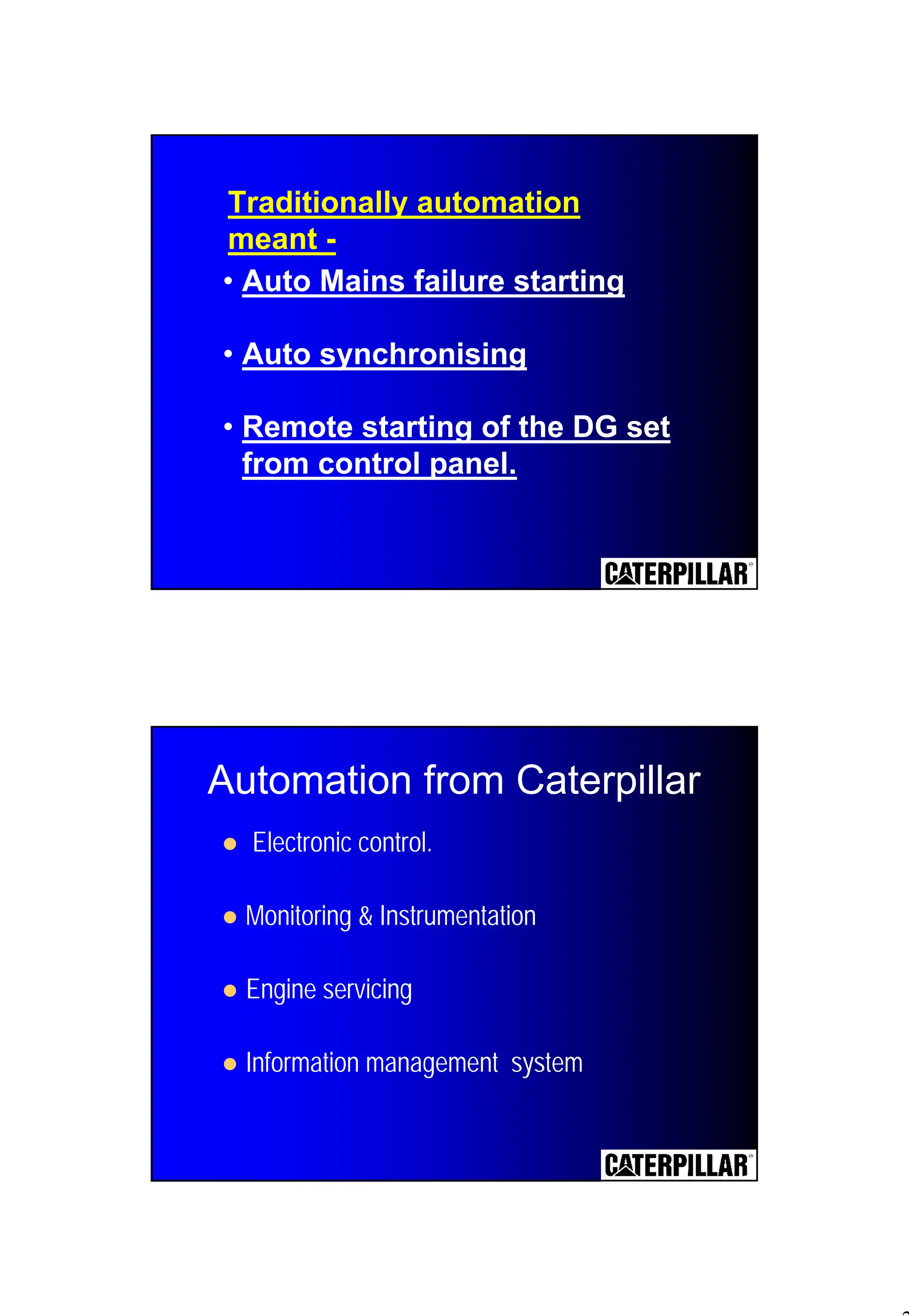
Traditionally automation
meant -
•Auto Mains failure starting
• Auto synchronising
• Remote starting of the DG set
from control panel.
Automation from Caterpillar
! Electronic control.
! Monitoring & Instrumentation
! Engine servicing
! Information management system
3.
3
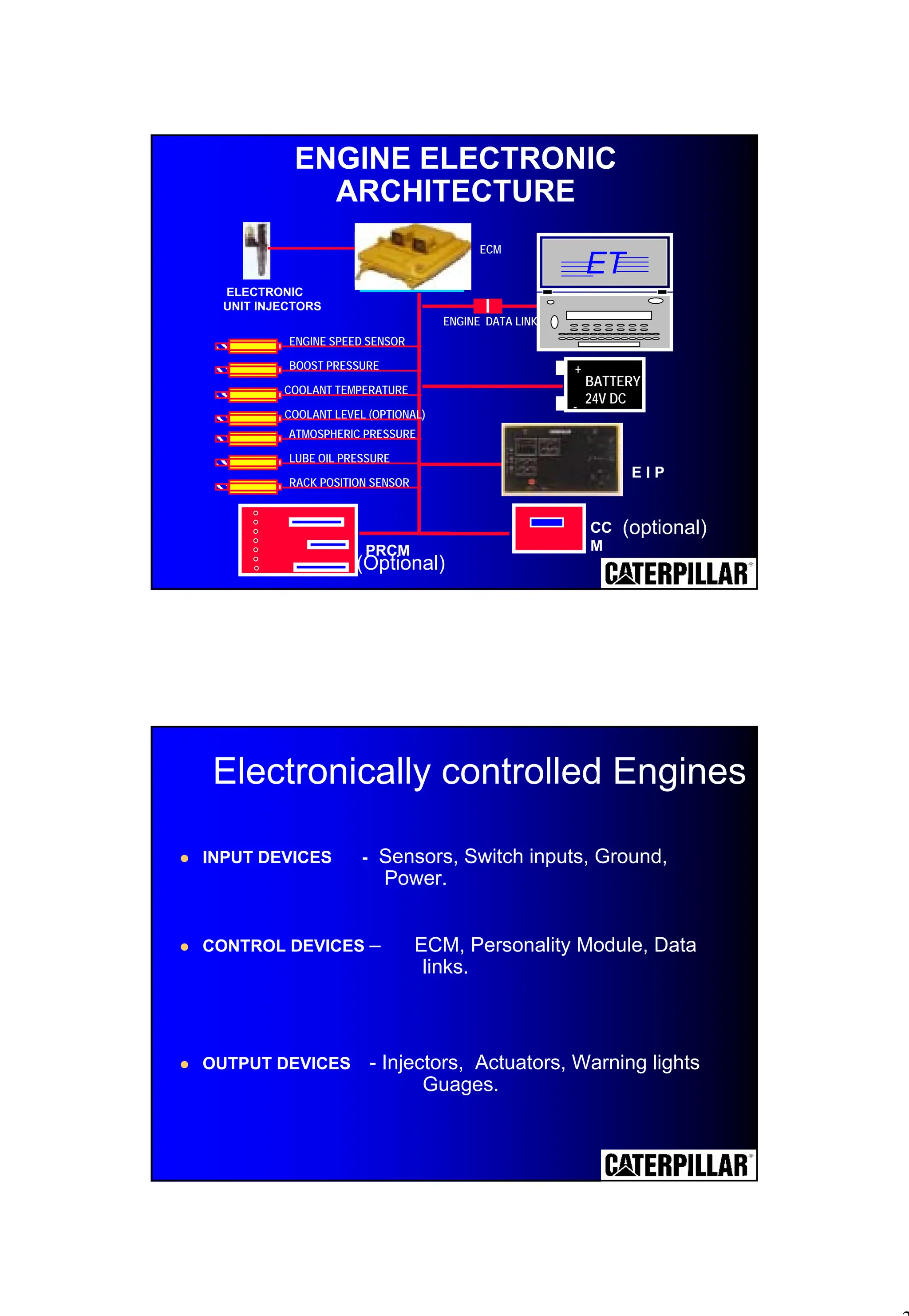
ENGINE ELECTRONIC
ARCHITECTURE
ECM
ENGINE DATALINK
BATTERY
24V DC
-
+
ENGINE SPEED SENSOR
BOOST PRESSURE
COOLANT TEMPERATURE
COOLANT LEVEL (OPTIONAL)
ATMOSPHERIC PRESSURE
LUBE OIL PRESSURE
RACK POSITION SENSOR
E I P
ELECTRONIC
UNIT INJECTORS
ET
CC
M
(optional)
PRCM
(Optional)
! INPUT DEVICES - Sensors, Switch inputs, Ground,
Power.
! CONTROL DEVICES – ECM, Personality Module, Data
links.
! OUTPUT DEVICES - Injectors, Actuators, Warning lights
Guages.
Electronically controlled Engines
4.
4
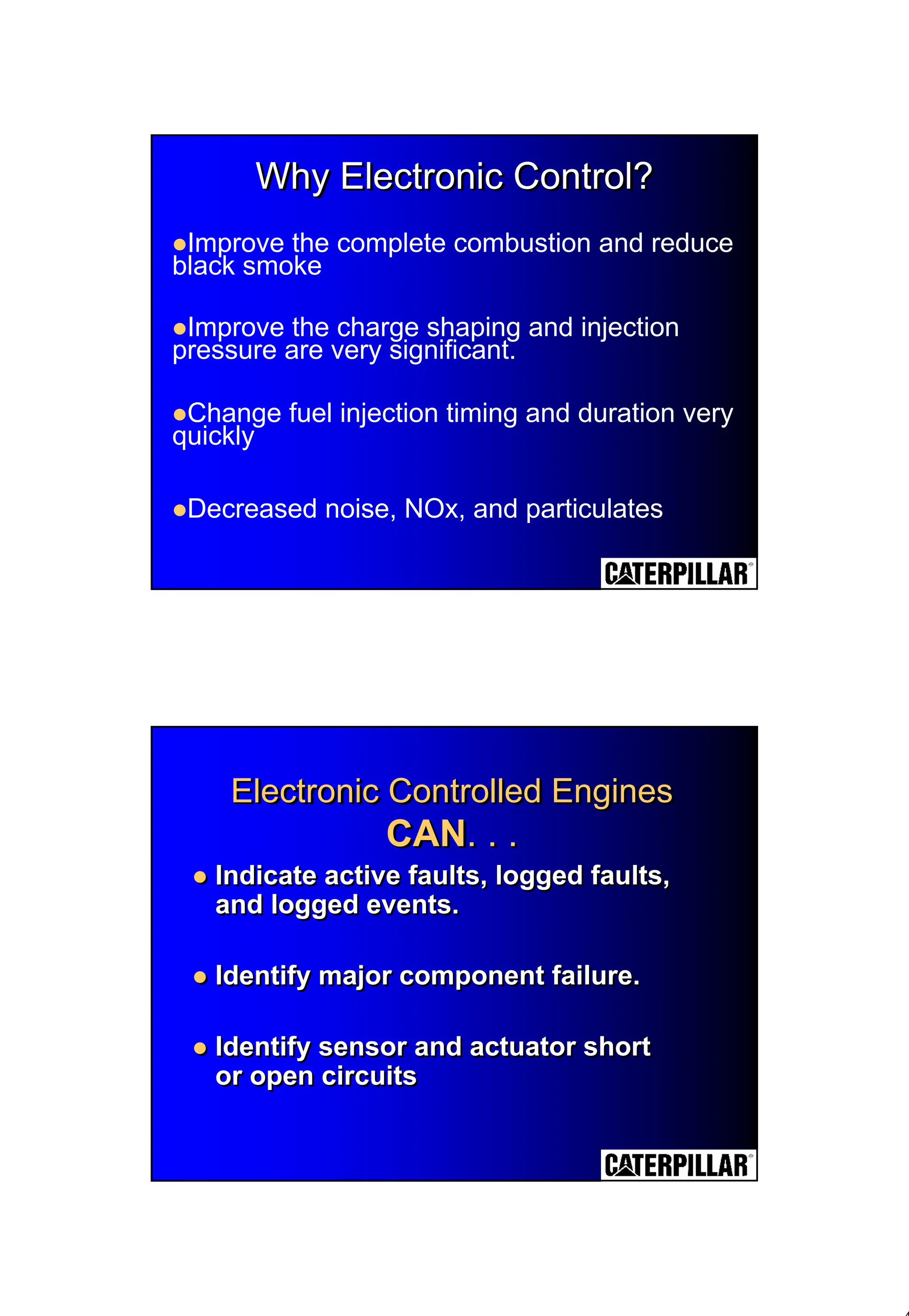
Why Electronic Control?
WhyElectronic Control?
Why Electronic Control?
!Improve the complete combustion and reduce
black smoke
!Improve the charge shaping and injection
pressure are very significant.
!Change fuel injection timing and duration very
quickly
!Decreased noise, NOx, and particulates
Electronic Controlled Engines
CAN. . .
Electronic Controlled Engines
Electronic Controlled Engines
CAN
CAN. . .
. . .
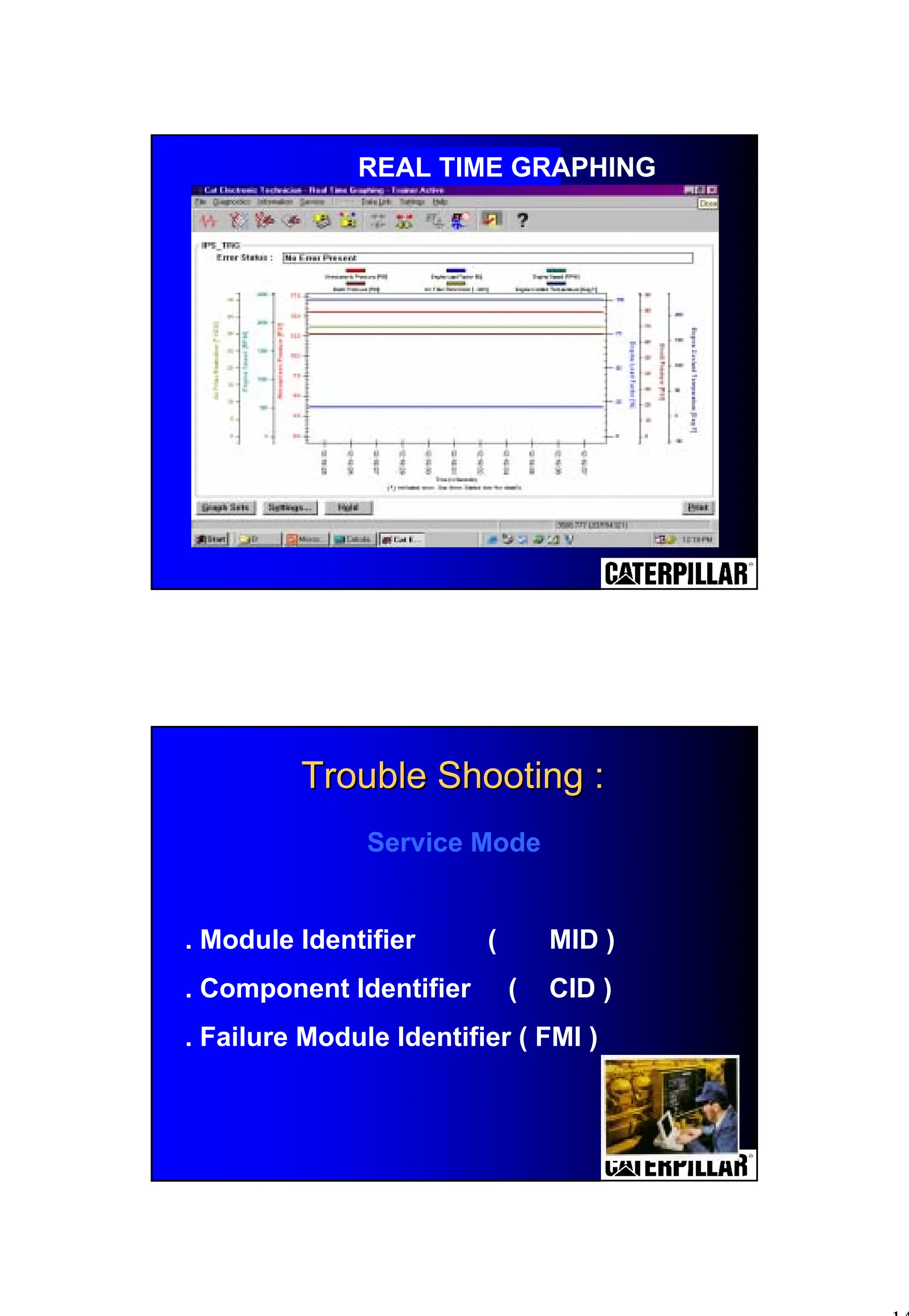
! Indicate active faults, logged faults,
and logged events.
! Identify major component failure.
! Identify sensor and actuator short
or open circuits
! Indicate active faults, logged faults,
and logged events.
! Identify major component failure.
! Identify sensor and actuator short
or open circuits
6
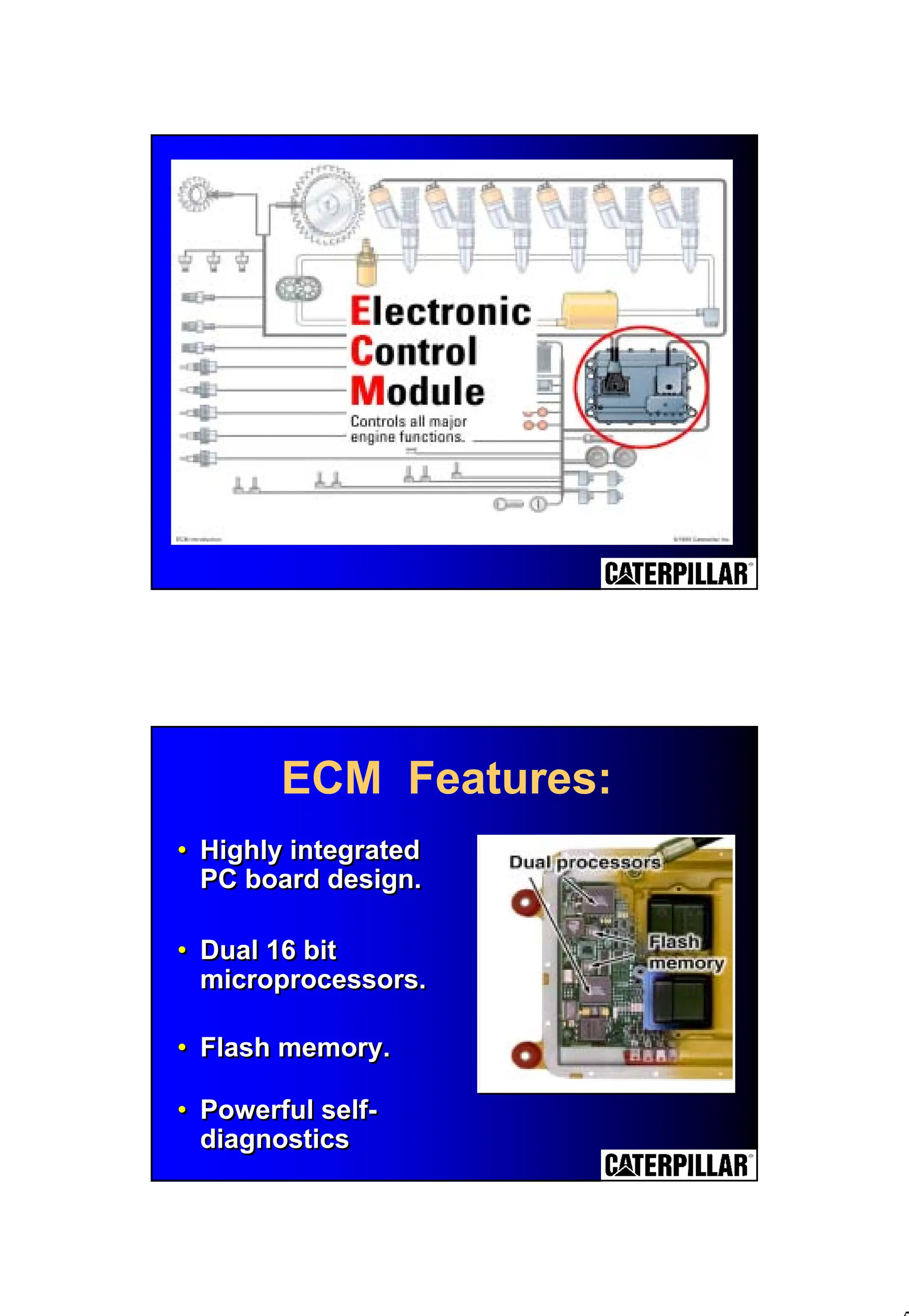
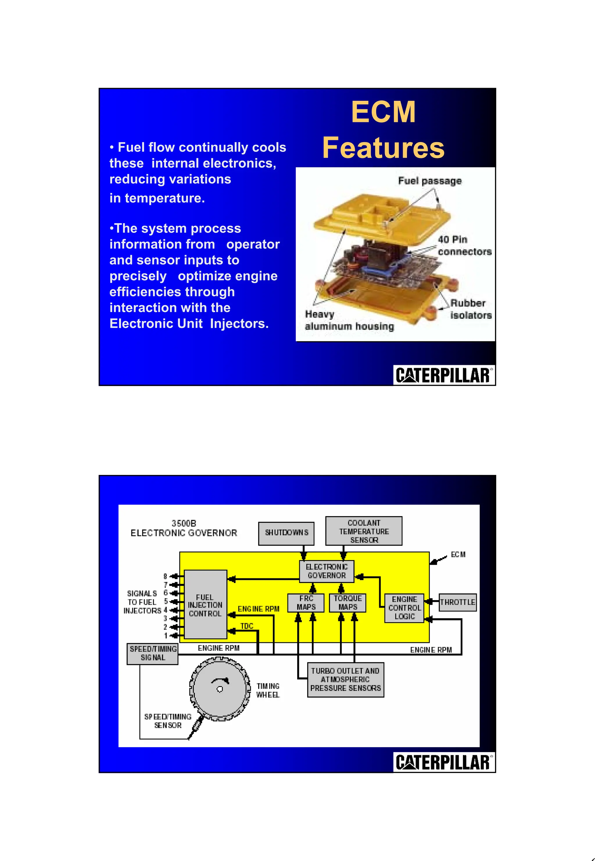
• Fuel flowcontinually cools
these internal electronics,
reducing variations
in temperature.
•The system process
information from operator
and sensor inputs to
precisely optimize engine
efficiencies through
interaction with the
Electronic Unit Injectors.
ECM
Features
7.
7
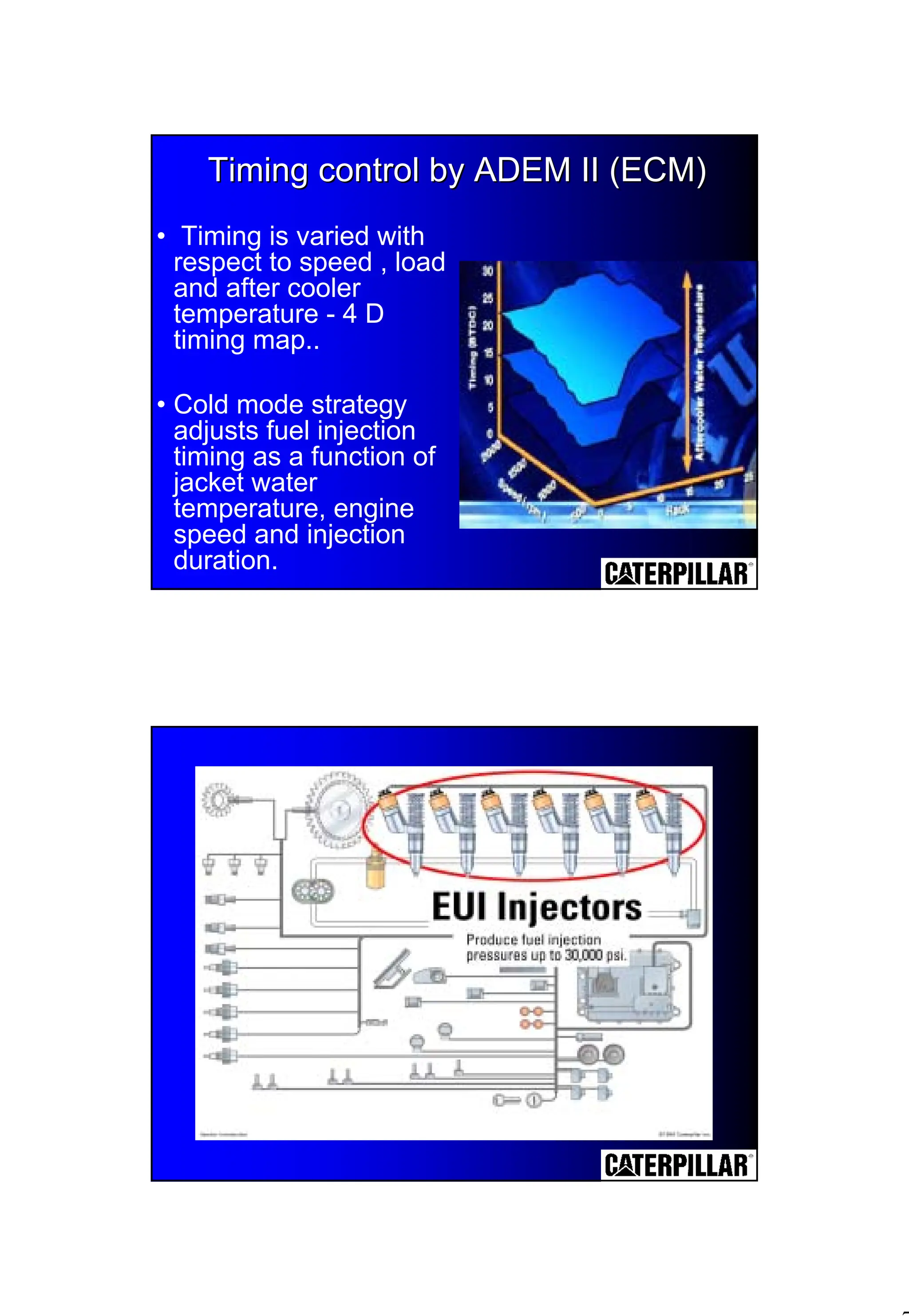
Timing control byADEM II (ECM)
Timing control by ADEM II (ECM)
• Timing is varied with
respect to speed , load
and after cooler
temperature - 4 D
timing map..
• Cold mode strategy
adjusts fuel injection
timing as a function of
jacket water
temperature, engine
speed and injection
duration.
9
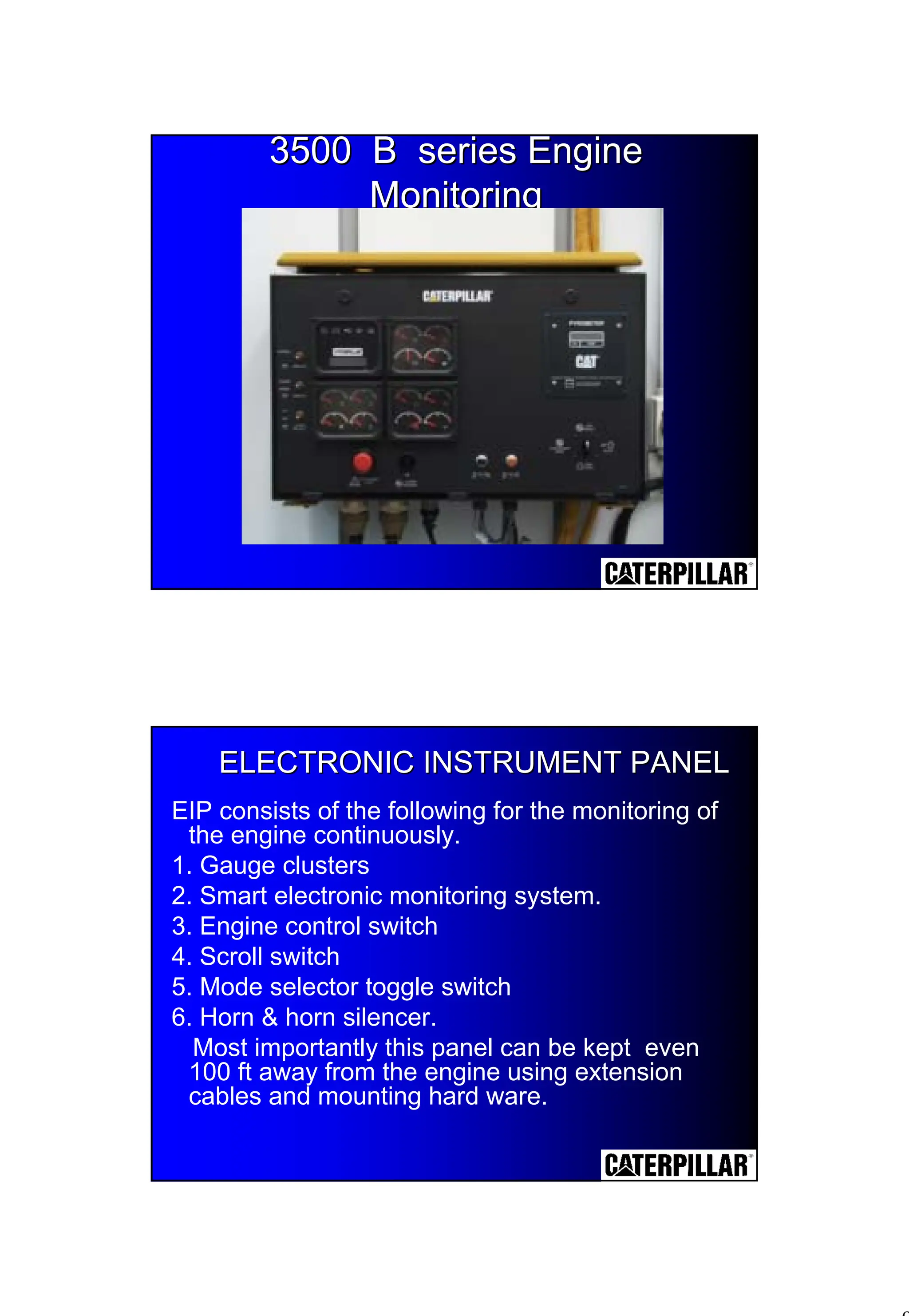
3500 B seriesEngine
3500 B series Engine
Monitoring
Monitoring
ELECTRONIC INSTRUMENT PANEL
ELECTRONIC INSTRUMENT PANEL
EIP consists of the following for the monitoring of
the engine continuously.
1. Gauge clusters
2. Smart electronic monitoring system.
3. Engine control switch
4. Scroll switch
5. Mode selector toggle switch
6. Horn & horn silencer.
Most importantly this panel can be kept even
100 ft away from the engine using extension
cables and mounting hard ware.
10.
10
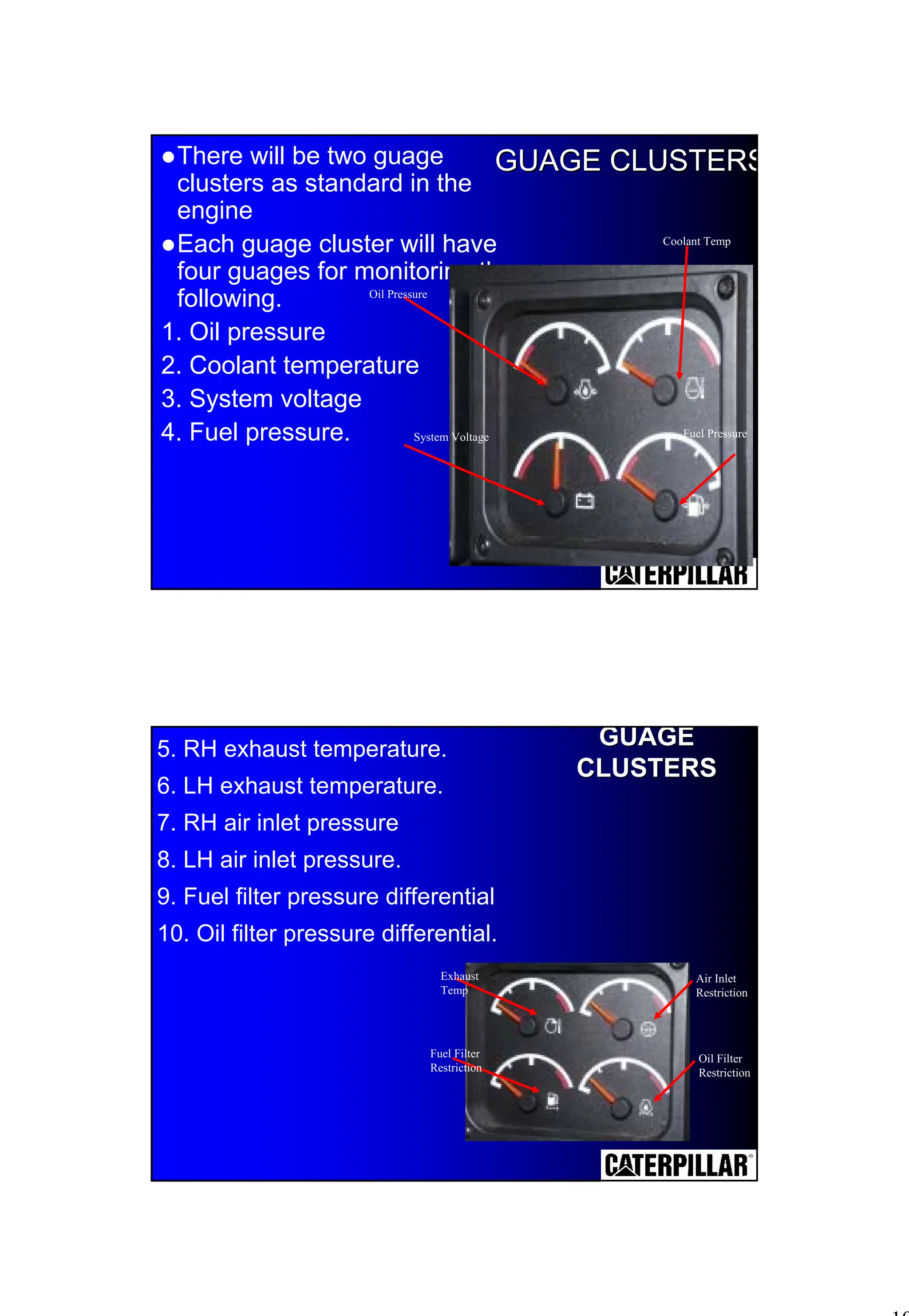
GUAGE CLUSTERS
GUAGE CLUSTERS
!Therewill be two guage
clusters as standard in the
engine
!Each guage cluster will have
four guages for monitoring the
following.
1. Oil pressure
2. Coolant temperature
3. System voltage
4. Fuel pressure.
Oil Pressure
System Voltage
Coolant Temp
Fuel Pressure
5. RH exhaust temperature.
6. LH exhaust temperature.
7. RH air inlet pressure
8. LH air inlet pressure.
9. Fuel filter pressure differential
10. Oil filter pressure differential.
Exhaust
Temp
Fuel Filter
Restriction
Air Inlet
Restriction
Oil Filter
Restriction
GUAGE
GUAGE
CLUSTERS
CLUSTERS
11.
11
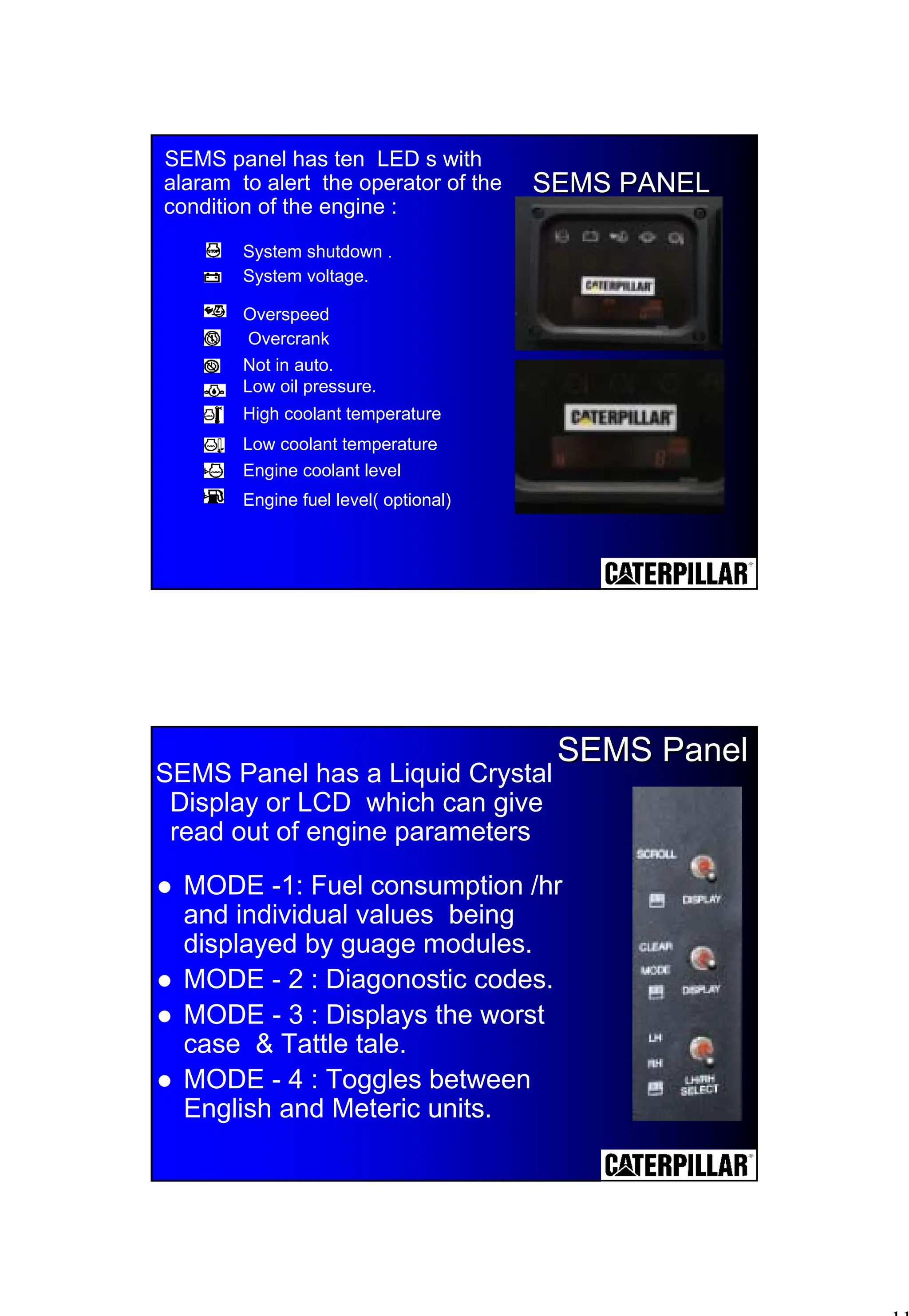
SEMS panel hasten LED s with
alaram to alert the operator of the
condition of the engine :
SEMS PANEL
SEMS PANEL
System shutdown .
System voltage.
Overspeed
Overcrank
Not in auto.
Low oil pressure.
High coolant temperature
Low coolant temperature
Engine coolant level
Engine fuel level( optional)
SEMS Panel has a Liquid Crystal
Display or LCD which can give
read out of engine parameters
SEMS Panel
SEMS Panel
! MODE -1: Fuel consumption /hr
and individual values being
displayed by guage modules.
! MODE - 2 : Diagonostic codes.
! MODE - 3 : Displays the worst
case & Tattle tale.
! MODE - 4 : Toggles between
English and Meteric units.
16
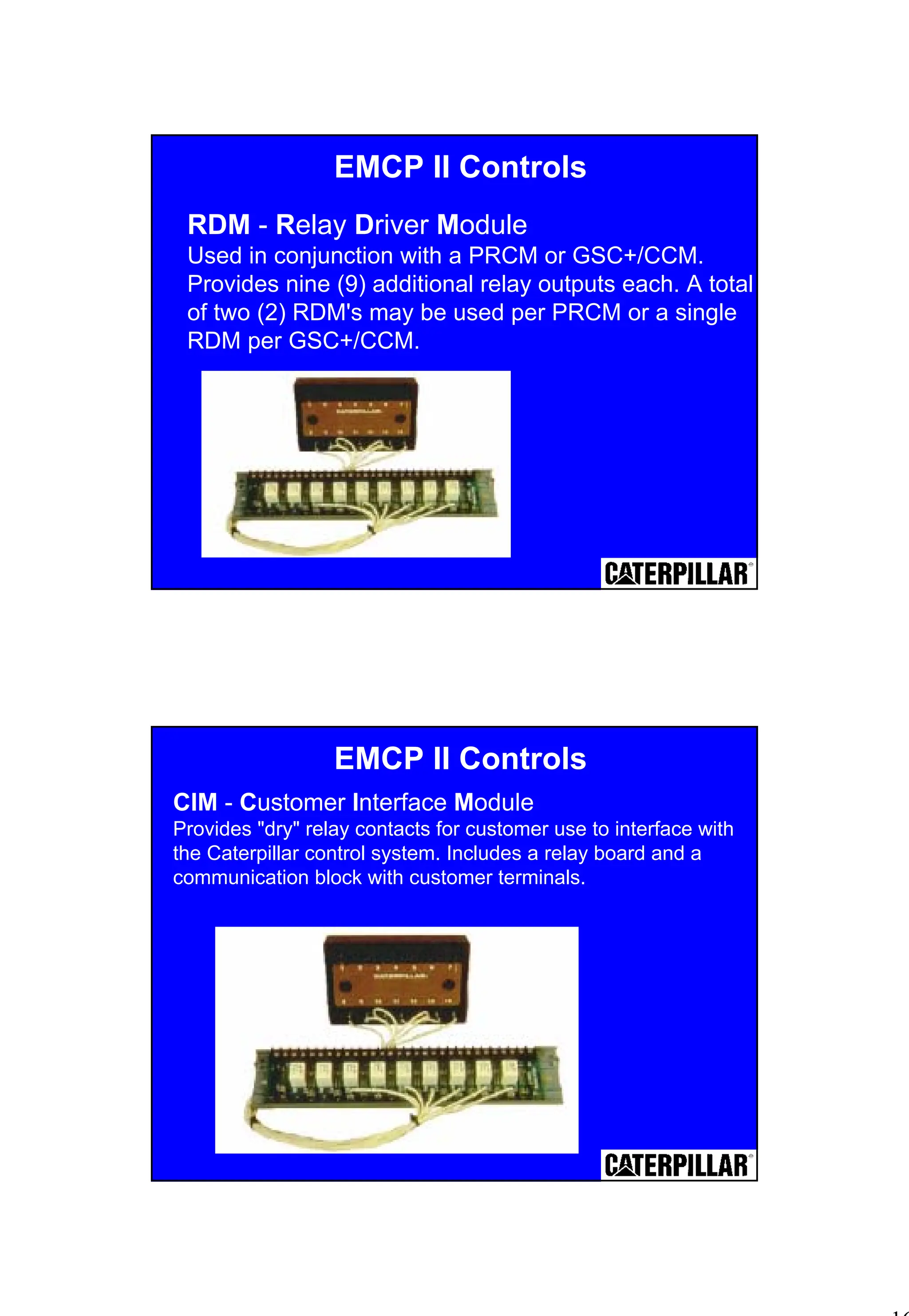
RDM - RelayDriver Module
Used in conjunction with a PRCM or GSC+/CCM.
Provides nine (9) additional relay outputs each. A total
of two (2) RDM's may be used per PRCM or a single
RDM per GSC+/CCM.
EMCP II Controls
EMCP II Controls
CIM - Customer Interface Module
Provides "dry" relay contacts for customer use to interface with
the Caterpillar control system. Includes a relay board and a
communication block with customer terminals.
17.
17
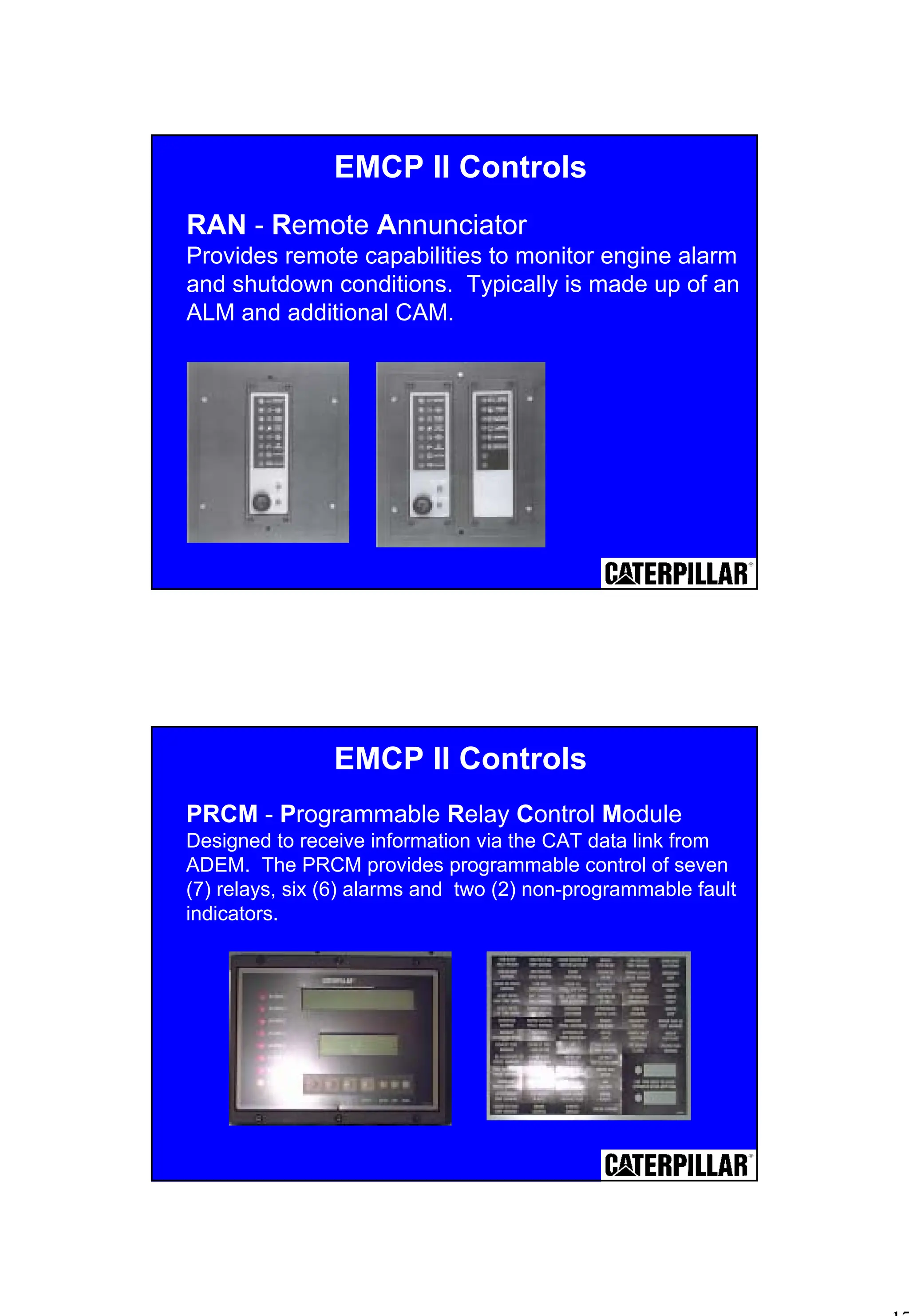
RAN - RemoteAnnunciator
Provides remote capabilities to monitor engine alarm
and shutdown conditions. Typically is made up of an
ALM and additional CAM.
EMCP II Controls
PRCM - Programmable Relay Control Module
Designed to receive information via the CAT data link from
ADEM. The PRCM provides programmable control of seven
(7) relays, six (6) alarms and two (2) non-programmable fault
indicators.
EMCP II Controls
18.
18
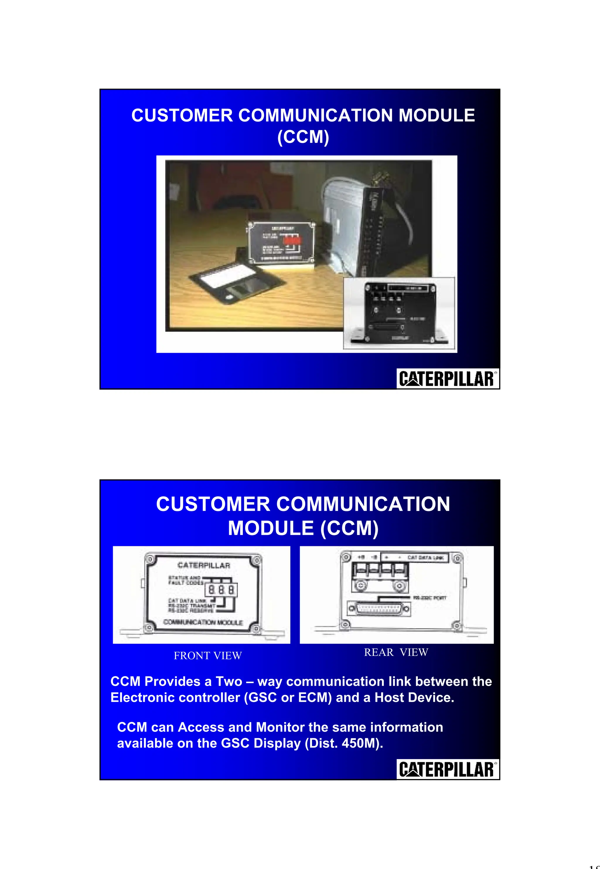
CUSTOMER COMMUNICATION MODULE
(CCM)
CCMcan Access and Monitor the same information
available on the GSC Display (Dist. 450M).
CUSTOMER COMMUNICATION
MODULE (CCM)
FRONT VIEW REAR VIEW
CCM Provides a Two – way communication link between the
Electronic controller (GSC or ECM) and a Host Device.
19.
19
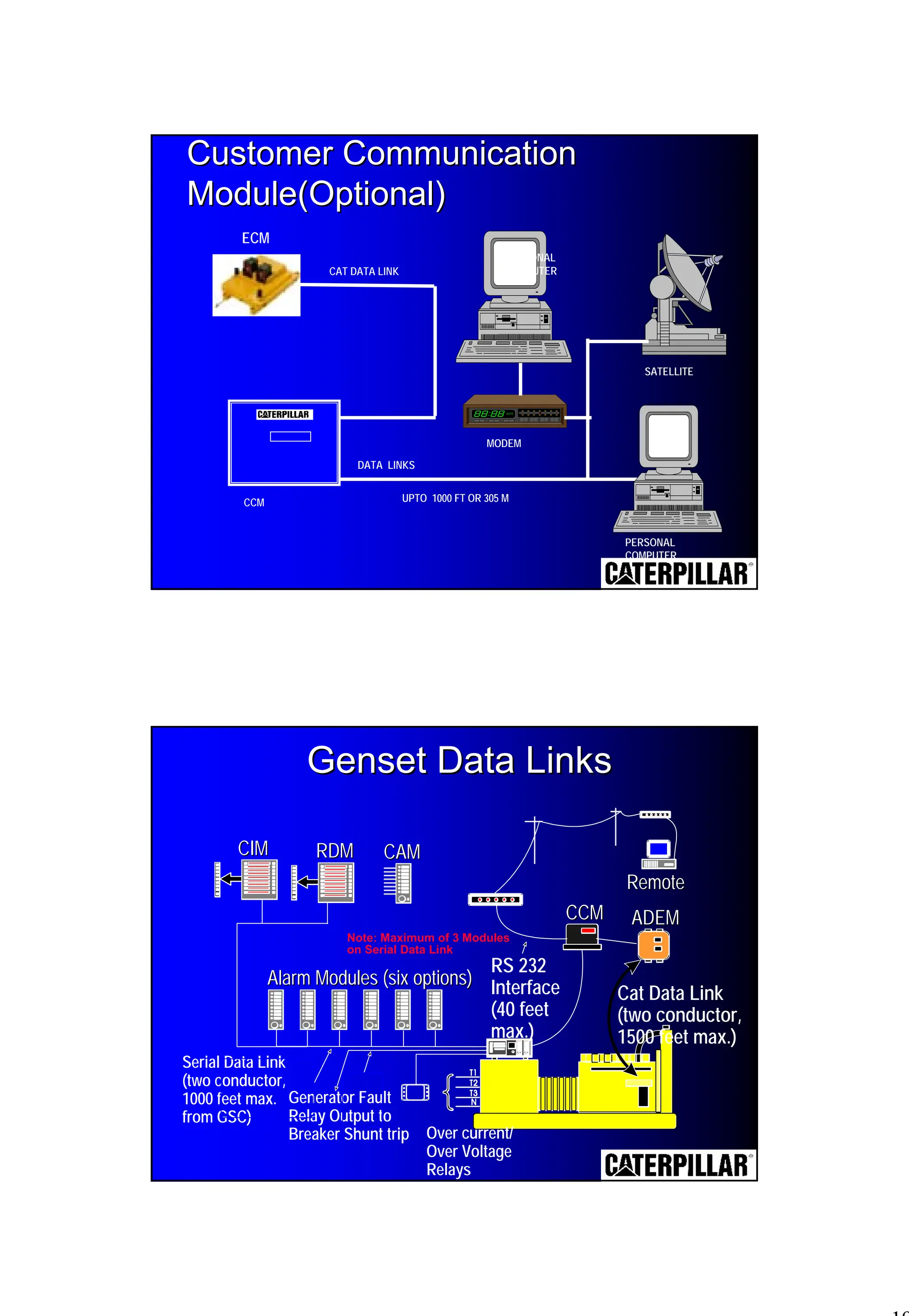
CAT DATA LINK
DATALINKS
UPTO 1000 FT OR 305 M
CCM
MODEM
SATELLITE
PERSONAL
COMPUTER
PERSONAL
COMPUTER
Customer Communication
Customer Communication
Module(Optional)
Module(Optional)
ECM
Genset Data Links
Genset Data Links
CAM
CAM
CIM
CIM
Alarm Modules (six options)
Alarm Modules (six options)
CCM
CCM ADEM
ADEM
Remote
Remote
RDM
RDM
Note: Maximum of 3 Modules
on Serial Data Link
Serial Data Link
(two conductor,
1000 feet max.
from GSC)
Generator Fault
Relay Output to
Breaker Shunt trip Over current/
Over Voltage
Relays
RS 232
Interface
(40 feet
max.)
Cat Data Link
(two conductor,
1500 feet max.)
20.
20
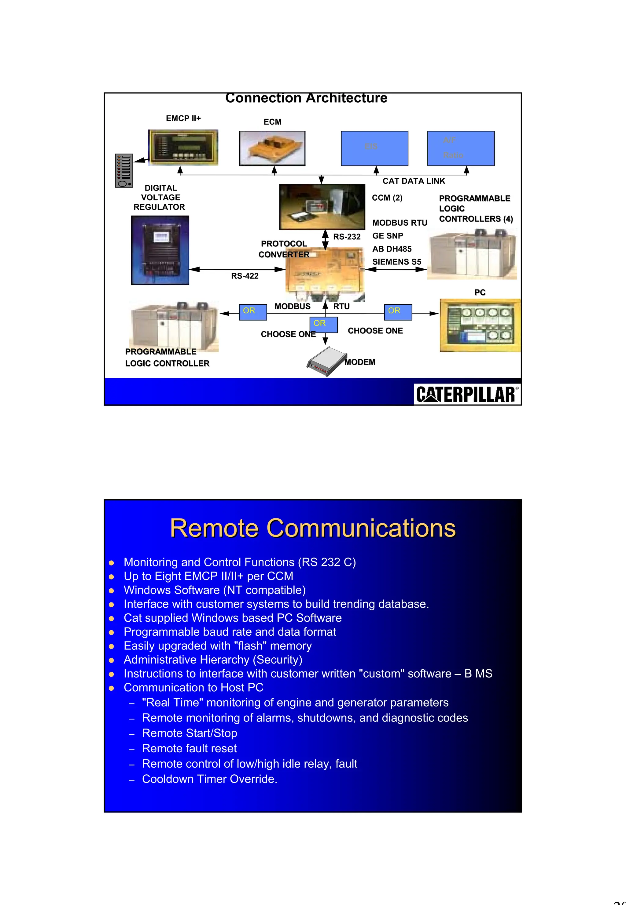
Connection Architecture
DIGITAL
VOLTAGE
REGULATOR
ECM
CCM (2)
EMCPII+
EIS
A/F
Ratio
PROTOCOL
PROTOCOL
CONVERTER
CONVERTER
RS-232
PROGRAMMABLE
PROGRAMMABLE
LOGIC
LOGIC
CONTROLLERS (4)
CONTROLLERS (4)
MODBUS RTU
GE SNP
AB DH485
SIEMENS S5
RS-422
CAT DATA LINK
OR OR
OR
MODBUS RTU
MODBUS RTU
CHOOSE ONE
CHOOSE ONE
CHOOSE ONE
CHOOSE ONE
PROGRAMMABLE
PROGRAMMABLE
LOGIC CONTROLLER
LOGIC CONTROLLER MODEM
MODEM
PC
PC
Remote Communications
Remote Communications
! Monitoring and Control Functions (RS 232 C)
! Up to Eight EMCP II/II+ per CCM
! Windows Software (NT compatible)
! Interface with customer systems to build trending database.
! Cat supplied Windows based PC Software
! Programmable baud rate and data format
! Easily upgraded with "flash" memory
! Administrative Hierarchy (Security)
! Instructions to interface with customer written "custom" software – B MS
! Communication to Host PC
– "Real Time" monitoring of engine and generator parameters
– Remote monitoring of alarms, shutdowns, and diagnostic codes
– Remote Start/Stop
– Remote fault reset
– Remote control of low/high idle relay, fault
– Cooldown Timer Override.
21.
21
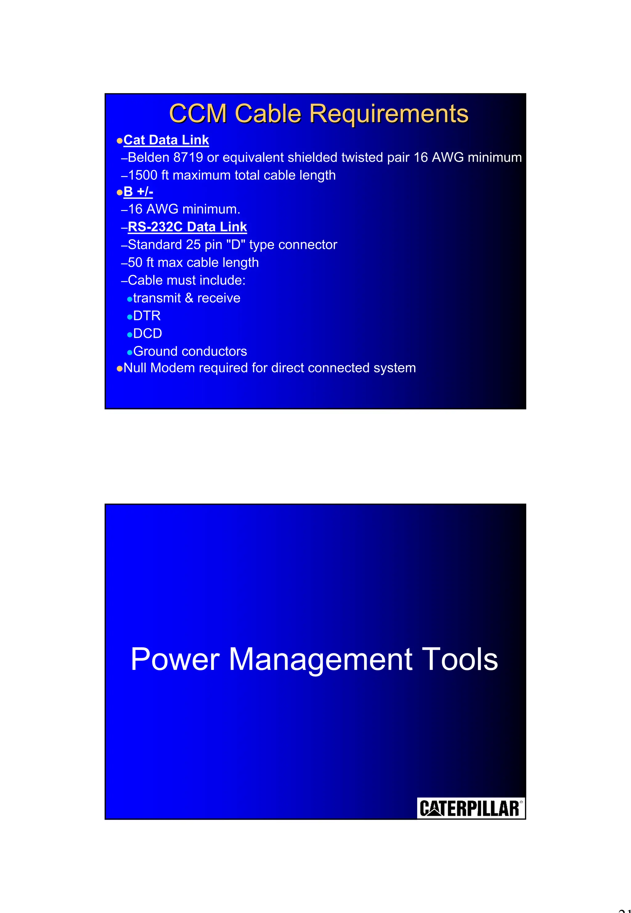
CCM Cable Requirements
CCMCable Requirements
!Cat Data Link
–Belden 8719 or equivalent shielded twisted pair 16 AWG minimum
–1500 ft maximum total cable length
!B +/-
–16 AWG minimum.
–RS-232C Data Link
–Standard 25 pin "D" type connector
–50 ft max cable length
–Cable must include:
!transmit & receive
!DTR
!DCD
!Ground conductors
!Null Modem required for direct connected system
Power Management Tools
22.
22
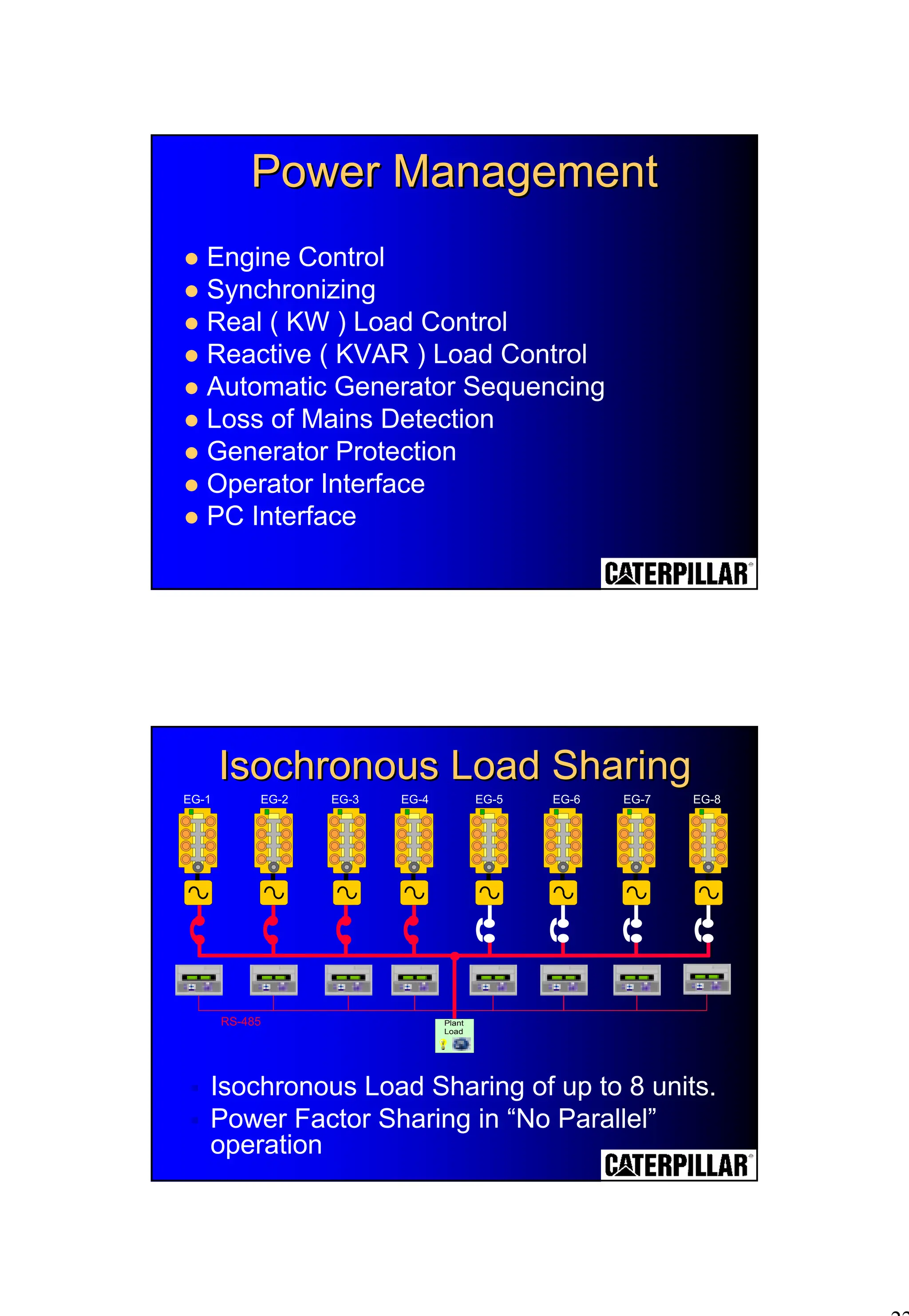
! Engine Control
!Synchronizing
! Real ( KW ) Load Control
! Reactive ( KVAR ) Load Control
! Automatic Generator Sequencing
! Loss of Mains Detection
! Generator Protection
! Operator Interface
! PC Interface
Power Management
Power Management
Isochronous Load Sharing
Isochronous Load Sharing
# Isochronous Load Sharing of up to 8 units.
# Power Factor Sharing in “No Parallel”
operation
Plant
Load
RS-485
EG-1 EG-2 EG-3 EG-4 EG-5 EG-6 EG-7 EG-8
23.
23
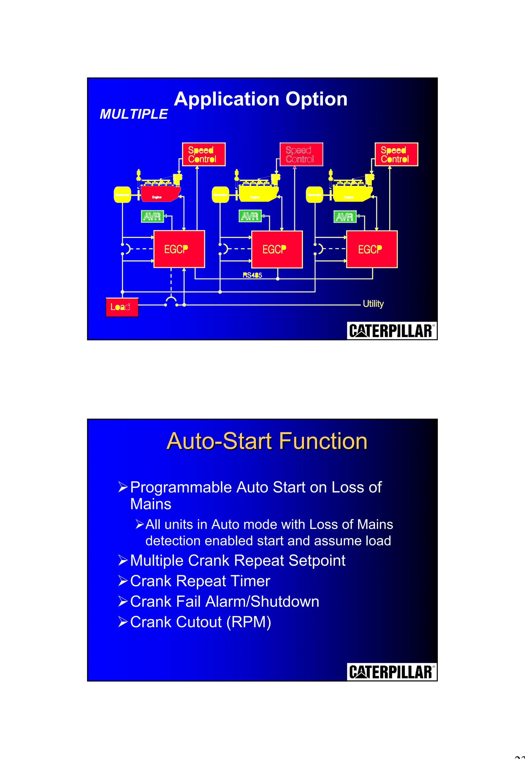
MULTIPLE
Application Option
Auto
Auto-
-Start Function
StartFunction
$Programmable Auto Start on Loss of
Mains
$All units in Auto mode with Loss of Mains
detection enabled start and assume load
$Multiple Crank Repeat Setpoint
$Crank Repeat Timer
$Crank Fail Alarm/Shutdown
$Crank Cutout (RPM)
24.
24
Loss of MainsDetection
! Mains Over / Under Voltage
! Mains Over / Under Frequency
! Dead Bus Closing
! Sync-check
! Manual Synchronization capability
–Sync Check is still active
Auto -Synchronising
25.
25
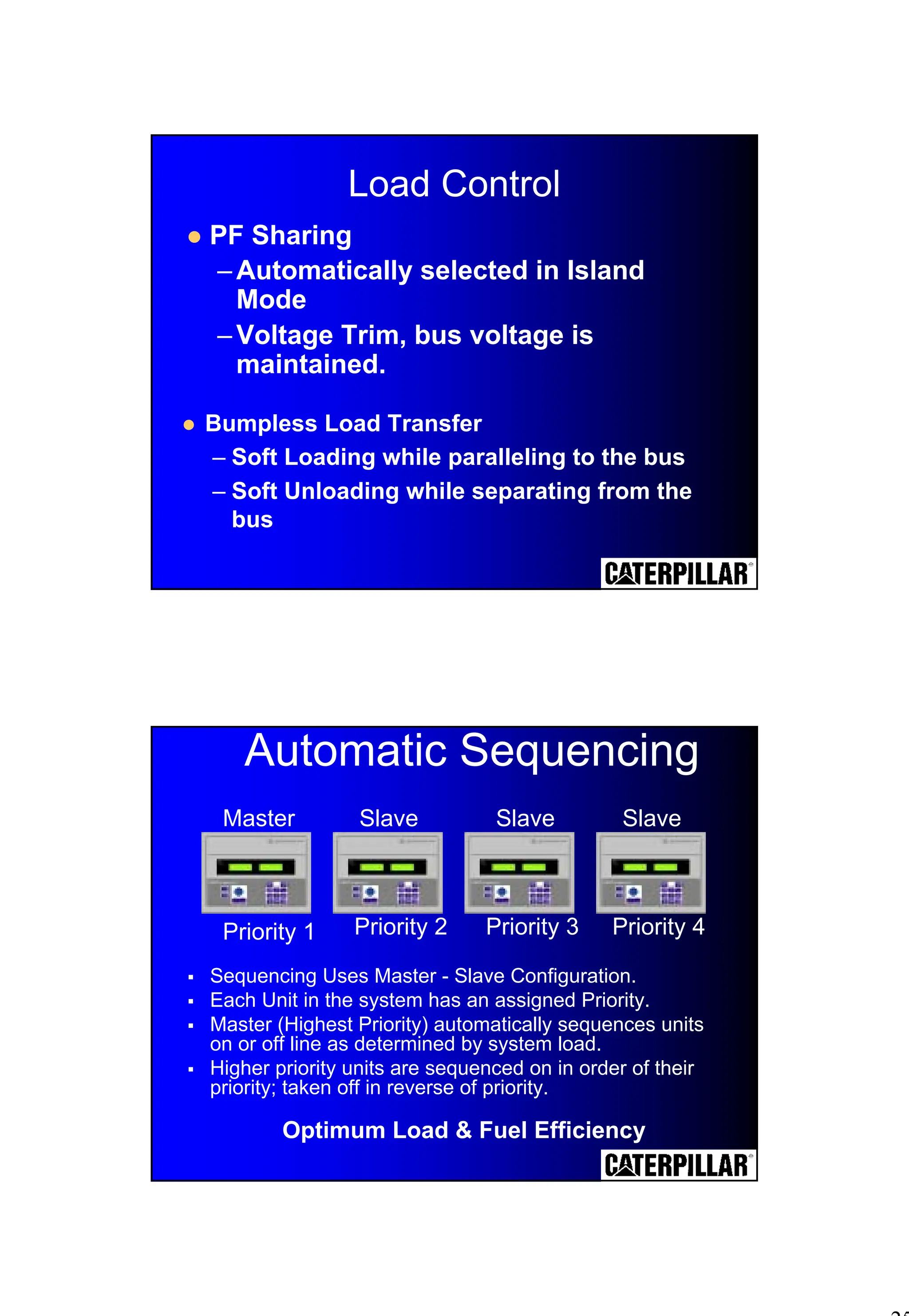
Load Control
! PFSharing
–Automatically selected in Island
Mode
–Voltage Trim, bus voltage is
maintained.
! Bumpless Load Transfer
– Soft Loading while paralleling to the bus
– Soft Unloading while separating from the
bus
Automatic Sequencing
# Sequencing Uses Master - Slave Configuration.
# Each Unit in the system has an assigned Priority.
# Master (Highest Priority) automatically sequences units
on or off line as determined by system load.
# Higher priority units are sequenced on in order of their
priority; taken off in reverse of priority.
Master Slave Slave Slave
Priority 1 Priority 2 Priority 3 Priority 4
Optimum Load & Fuel Efficiency
26.
26
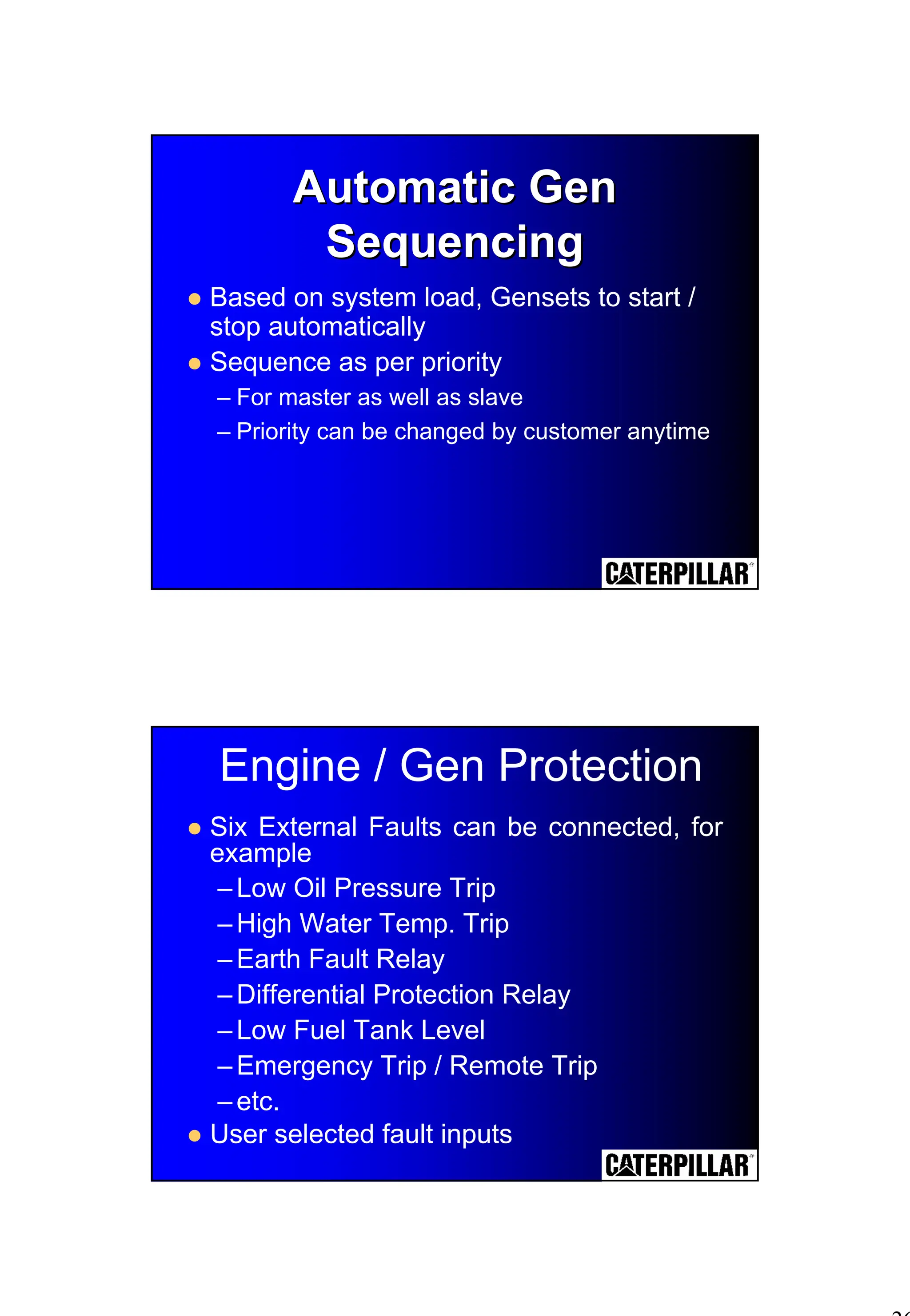
Automatic Gen
Automatic Gen
Sequencing
Sequencing
!Based on system load, Gensets to start /
stop automatically
! Sequence as per priority
– For master as well as slave
– Priority can be changed by customer anytime
Engine / Gen Protection
! Six External Faults can be connected, for
example
–Low Oil Pressure Trip
–High Water Temp. Trip
–Earth Fault Relay
–Differential Protection Relay
–Low Fuel Tank Level
–Emergency Trip / Remote Trip
–etc.
! User selected fault inputs
27.
27
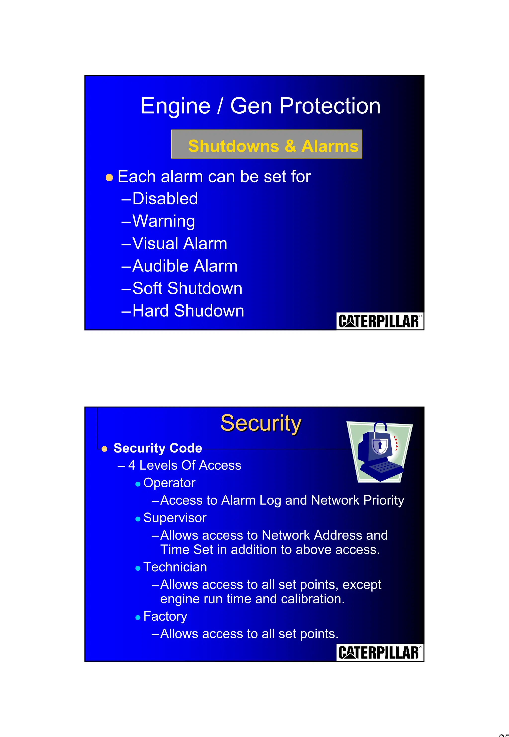
Engine / GenProtection
! Each alarm can be set for
–Disabled
–Warning
–Visual Alarm
–Audible Alarm
–Soft Shutdown
–Hard Shudown
Shutdowns & Alarms
! Security Code
– 4 Levels Of Access
! Operator
–Access to Alarm Log and Network Priority
! Supervisor
–Allows access to Network Address and
Time Set in addition to above access.
! Technician
–Allows access to all set points, except
engine run time and calibration.
! Factory
–Allows access to all set points.
Security
Security
28.
28
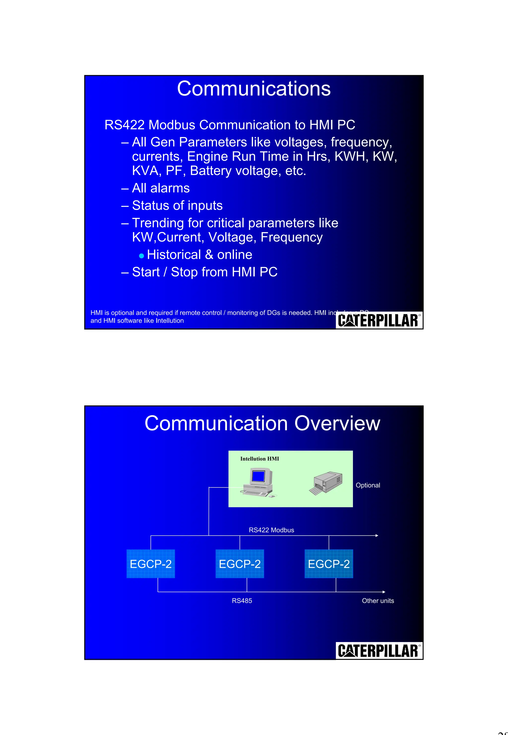
Communications
RS422 Modbus Communicationto HMI PC
– All Gen Parameters like voltages, frequency,
currents, Engine Run Time in Hrs, KWH, KW,
KVA, PF, Battery voltage, etc.
– All alarms
– Status of inputs
– Trending for critical parameters like
KW,Current, Voltage, Frequency
! Historical & online
– Start / Stop from HMI PC
HMI is optional and required if remote control / monitoring of DGs is needed. HMI includes a PC
and HMI software like Intellution
EGCP-2 EGCP-2 EGCP-2
Intellution HMI
Optional
RS422 Modbus
RS485 Other units
Communication Overview


![Caterpillar Diesel Engine Control Systems [PDF, ENG, 588 KB].pdf](https://cdn.slidesharecdn.com/ss_thumbnails/caterpillardieselenginecontrolsystemspdfeng588kb-220908204320-d8164ccc-thumbnail.jpg?width=640&height=640&fit=bounds)


