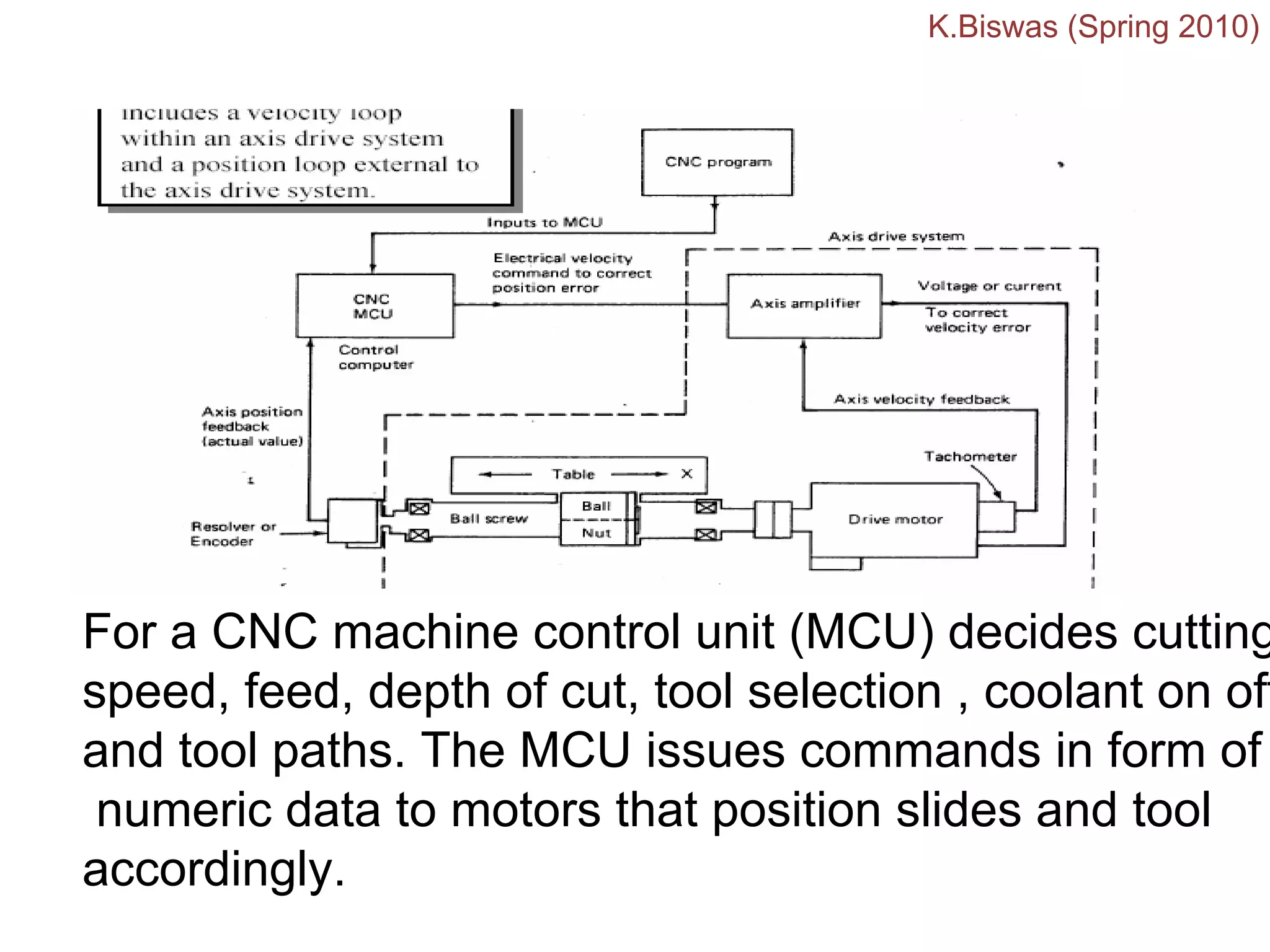
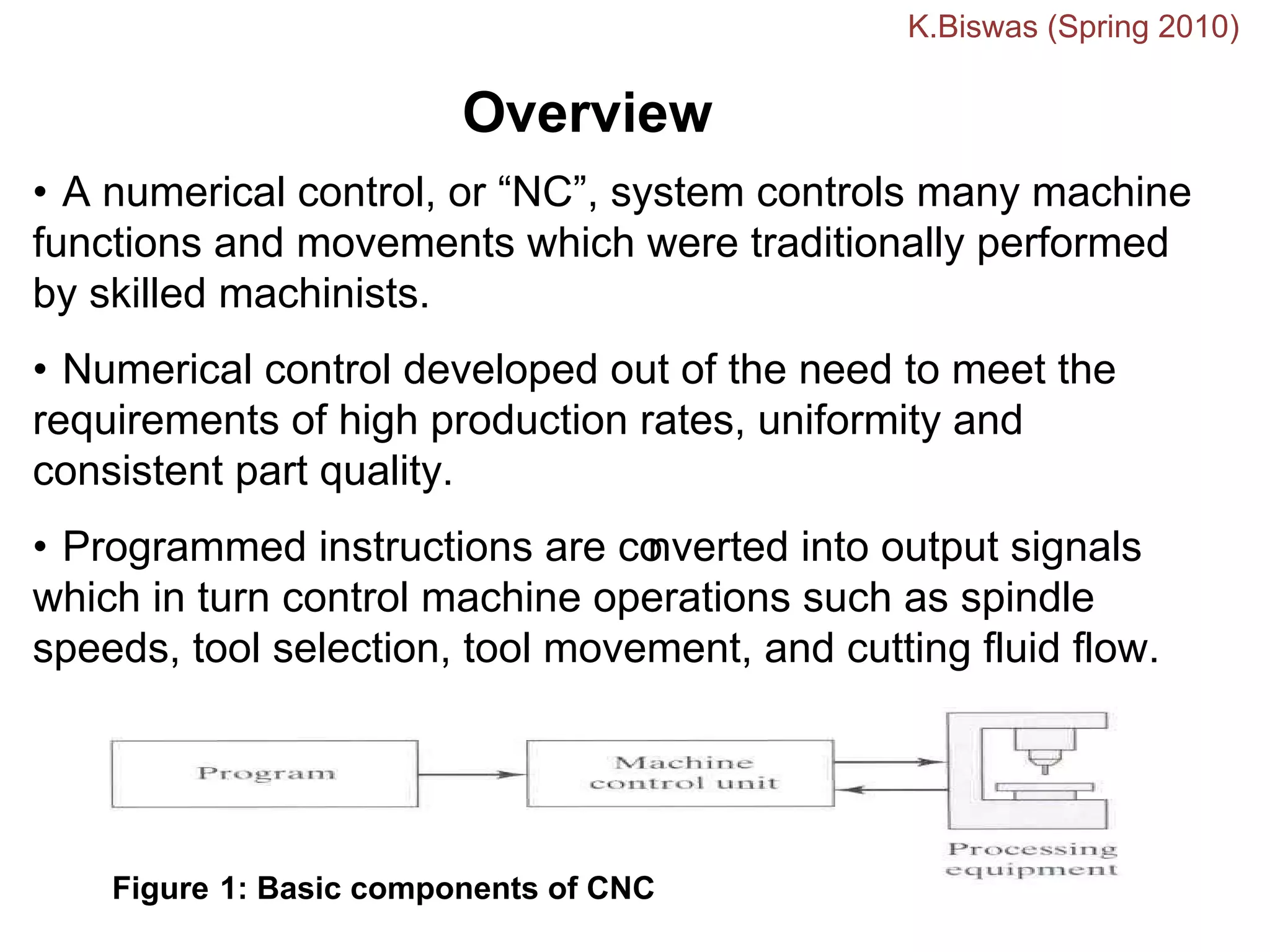
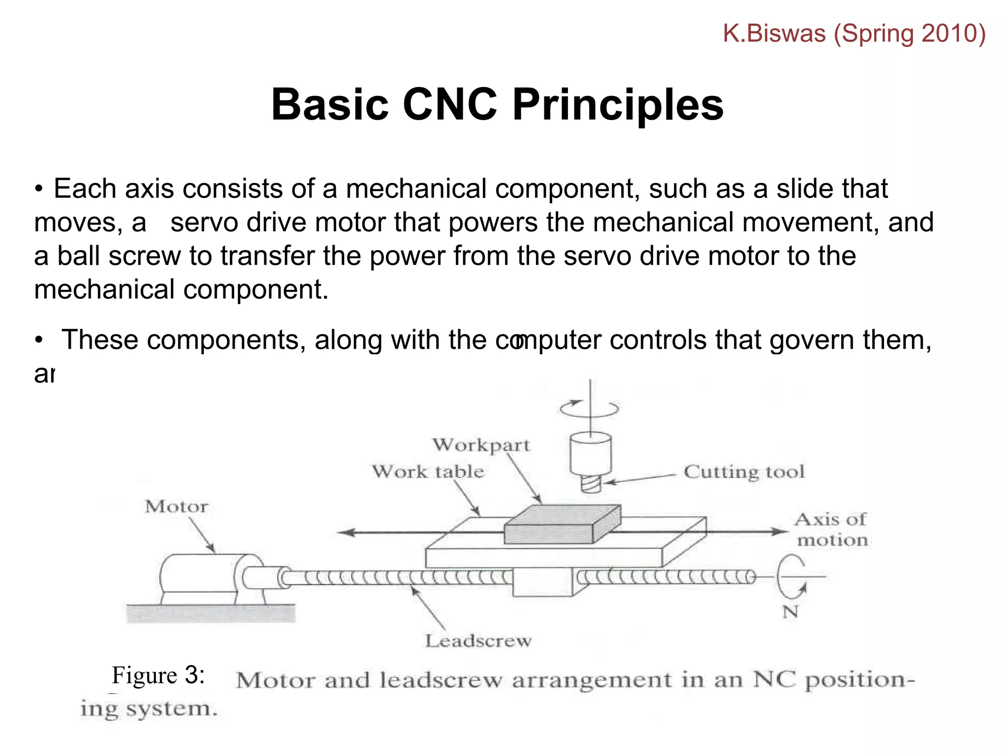
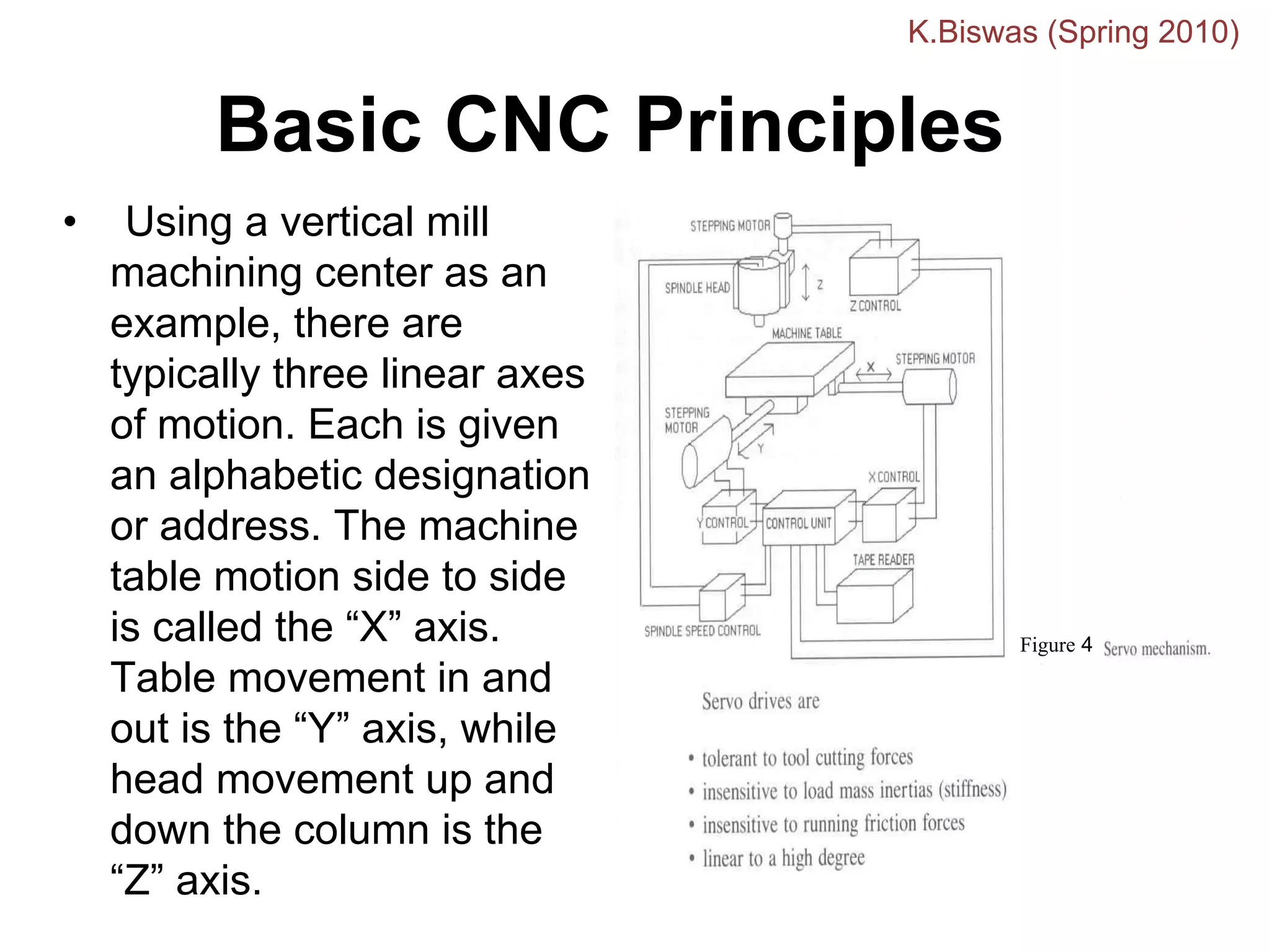
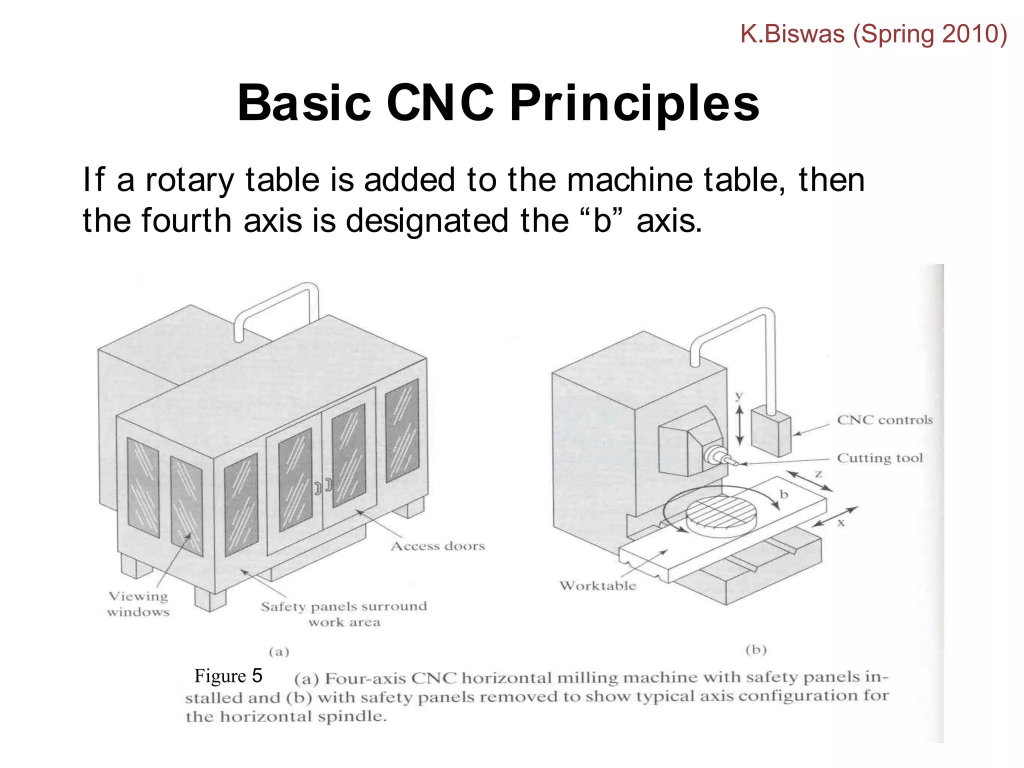
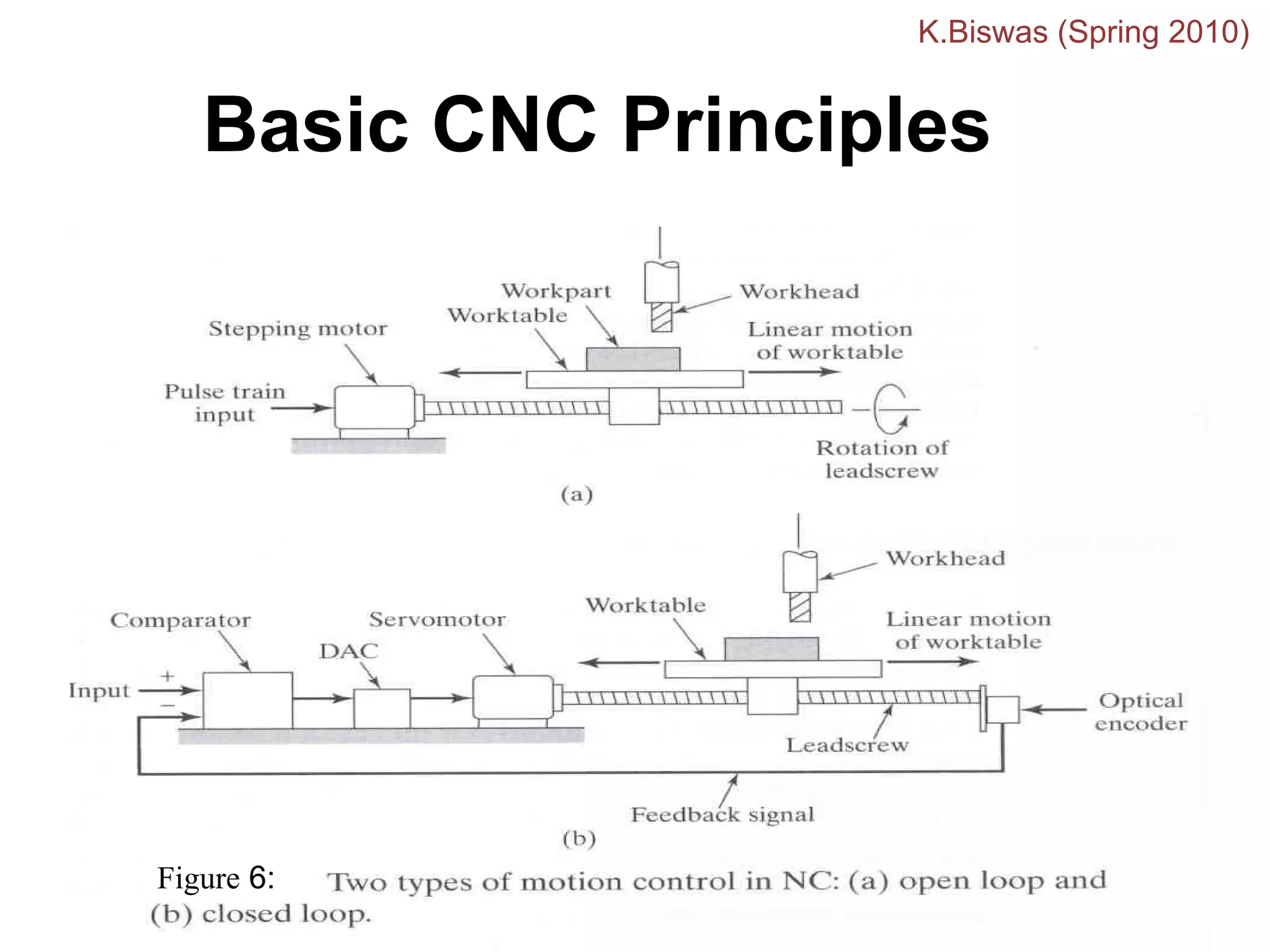
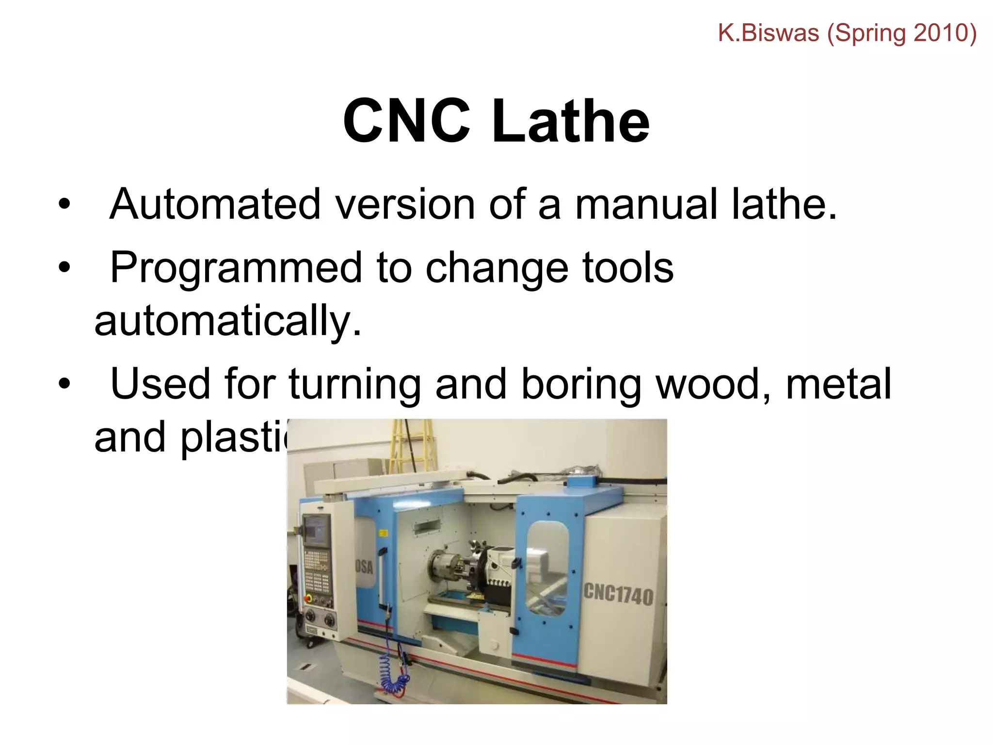
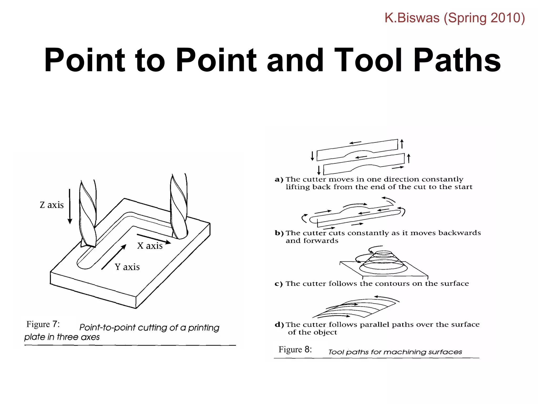
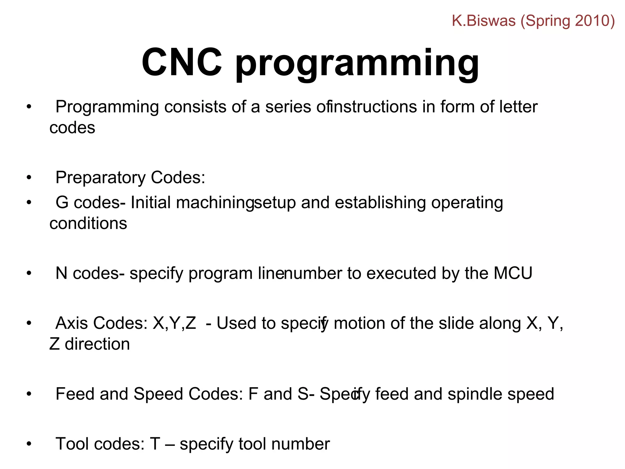
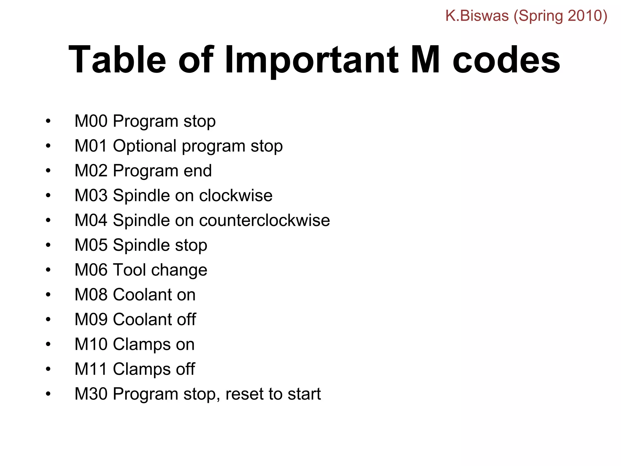
Introduction to
CNCMachining
Krishanu Biswas
Department of Materials and Metallurgical Engineering
IIT Kanpur
CNC Machines
• What is a CNC Machine?
• CNC : Computer and Numeric Control
• Conventionally, an operator decides and adjusts
various machines parameters like feed , depth of
cut etc depending on type of job , and controls
the slide movements by hand. In a CNC
Machine functions and slide movements are
controlled by motors using computer programs.
K.Biswas (Spring 2010)
For a CNC machine control unit (MCU) decides cutting
speed, feed, depth of cut, tool selection , coolant on off
and tool paths. The MCU issues commands in form of
numeric data to motors that position slides and tool
accordingly.
K.Biswas (Spring 2010)
Overview
• A numerical control, or “NC”, system controls many machine
functions and movements which were traditionally performed
by skilled machinists.
• Numerical control developed out of the need to meet the
requirements of high production rates, uniformity and
consistent part quality.
• Programmed instructions are co
nverted into output signals
which in turn control machine operations such as spindle
speeds, tool selection, tool movement, and cutting fluid flow.
Figure 1: Basic components of CNC
K.Biswas (Spring 2010)
Overview
• By integrating a computer processor, computer
numerical control, or “CNC” as it is now known,
allows part machining programs to be edited and
stored in the computer memory as well as
permitting diagnostics and quality control functions
during the actual machining.
• All CNC machining begins with a part program,
which is a sequential instructions or coded
commands that direct the specific machine
functions.
• The part program may be manually generated or,
more commonly, generated by computer aided part
K.Biswas (Spring 2010)
Basic CNC Principles
All computer controlled machines are able to accurately and
repeatedly control motion in various directions. Each of these
directions of motion is called an axis. Depending on the machine type
there are commonly two to five axes.
Additionally, a CNC axis may be either a linear axis in which
movement is in a straight line, or a rotary axis with motion following a
circular path.
Figure 2:
K.Biswas (Spring 2010)
Motion control - the heart of
CNC
• The most basic function ofany CNC machine is automatic,
precise, and consistent motion control.
• Rather than applying completely mechanical devices to
cause motion as is required on most conventional machine
tools, CNC machines allow motion control in a
revolutionary manner.
• All forms of CNC equipment have two or more directions
of motion, called axes. These axes can be precisely and
automatically positioned along their lengths of travel.
• The two most common axis types are linear (driven along
a straight path) and rotary (driven along a circular path).
K.Biswas (Spring 2010)
Basic CNC Principles
Coordinates System
Absolute Coordinate System Incremental Coordinate System
K.Biswas (Spring 2010)
Basic CNC Principles
• Each axis consists of a mechanical component, such as a slide that
moves, a servo drive motor that powers the mechanical movement, and
a ball screw to transfer the power from the servo drive motor to the
mechanical component.
• These components, along with the co
mputer controls that govern them,
are referred to as an axis drive system.
Figure 3:
K.Biswas (Spring 2010)
Basic CNC Principles
• Using a vertical mill
machining center as an
example, there are
typically three linear axes
of motion. Each is given
an alphabetic designation
or address. The machine
table motion side to side
is called the “X” axis.
Table movement in and
out is the “Y” axis, while
head movement up and
down the column is the
“Z” axis.
Figure 4
K.Biswas (Spring 2010)
Basic CNC Principles
If a rotary table is added to the machine table, then
the fourth axis is designated the “b” axis.
Figure 5
K.Biswas (Spring 2010)
• The method of accurate work positioningin relation to the cutting tool is
called the “rectangular coordinate system.” On the vertical mill, the
horizontal base line is designated the “X” axis, while the vertical base line
is designated the “Y” axis. The “Z” axis is at a right angle, perpendicular to
both the “X” and “Y” axes.
• Increments for all base lines are spec
ified in linear measurements, for
most machines the smallest increment is one ten-thousandth of an inch
(.0001). If the machine is graduated in metric the smallest increment is
usually one thousandth of a millimeter (.001mm).
• The rectangular coordinate system allo
ws the mathematical plotting of
points in space. These points or locations are called “coordinates.” The
coordinates in turn relate to the tool center and dictate the “tool path”
through the work.
Work Positioning
K.Biswas (Spring 2010)
Basic CNC Principles
Figure 6:
K.Biswas (Spring 2010)
CNC Machines-
Advantages/Disadvantages
Advantages:
• High Repeatability and Precision e.g. Aircraft parts
• Volume of production is very high
• Complex contours/surfaces needto be machined. E.g. Turbines
• Flexibility in job change, automatic tool settings, less scrap
• More safe, higher productivity, better quality
• Less paper work, faster prototypeproduction, reduction in lead times
Disadvantages:
• Costly setup, skilled operators
• Computers, programming knowledge required
• Maintenance is difficult
K.Biswas (Spring 2010)
Types of Machine
• Lathes for metal and plastics
– Used to produce 3D product shapes and
moulds for plastic products.
• Milling machine for mould making and
surface milling.
– Used to produce dies for
die cutting printed products.
K.Biswas (Spring 2010)
CNC Lathe
• Automated version of a manual lathe.
• Programmed to change tools
automatically.
• Used for turning and boring wood, metal
and plastic.
K.Biswas (Spring 2010)
CNC Milling Machine
• Has 3 to 5 axes.
• Used for wood, metal and plastic.
• Used to make 3D prototypes, moulds,
cutting dies, printing plates and signs.
K.Biswas (Spring 2010)
How CNC Works
• Controlled by G and M codes.
• These are number values and co-
ordinates.
• Each number or code is assigned to a
particular operation.
• Typed in manually to CAD by machine
operators.
• G&M codes are automatically generated
by the computer software.
K.Biswas (Spring 2010)
Features of CNC Machinery
• The tool or material moves.
• Tools can operate in 1-5 axes.
• Larger machines have a machine control
unit (MCU) which manages operations.
• Movement is controlled by a motors
(actuators).
• Feedback is provided by sensors
(transducers)
• Tool magazines are used to change tools
K.Biswas (Spring 2010)
Tools
• Most are made from
high speed steel (HSS),
tungsten carbide or ceramics.
• Tools are designed to direct waste away
from the material.
• Some tools need coolant such as oil to
protect the tool and work.
K.Biswas (Spring 2010)
Tool Paths, Cutting
and Plotting Motions
• Tool paths describes the route the cutting tool takes.
• Motion can be described as point to point, straight
cutting or contouring.
• Speeds are the rate at which the tool operates e.g. rpm.
• Feeds are the rate at which the cutting tool and work
piece move in relation to each other.
• Feeds and speeds are determined by cutting depth,
material and quality of finish needed. e.g. harder
materials need slower feeds and speeds.
• Rouging cuts remove larger amounts of material than
finishing cuts.
• Rapid traversing allows the tool or work piece to move
rapidly when no machining is taking place.
K.Biswas (Spring 2010)
Point to Point and Tool Paths
Figure 7:
Figure 8:
K.Biswas (Spring 2010)
CNC Programming Basics
• CNC instructions are called part program commands.
• When running, a part program is interpreted one
command line at a time until all lines are completed.
• Commands, which are also referred to as blocks, are
made up of words which each begin with a letter address
and end with a numerical value.
K.Biswas (Spring 2010)
CNC Programming Basics
• Each letter address relates to a specific machine
function. “G” and “M” letter addresses are two of the
most common. A “G” letter specifies certain machine
preparations such as inch or metric modes, or absolutes
versus incremental modes.
• A “M” letter specifies miscellaneous machine functions
and work like on/off switches for coolant flow, tool
changing, or spindle rotation. Other letter addresses are
used to direct a wide variety of other machine
commands.
K.Biswas (Spring 2010)
CNC programming
Important things to know:
• Coordinate System
• Units, incremental or absolute positioning
• Coordinates: X,Y,Z, RX,RY,RZ
• Feed rate and spindle speed
• Coolant Control: On/Off, Flood, Mist
• Tool Control: Tool and tool parameters
K.Biswas (Spring 2010)
• Programming consists of a series ofinstructions in form of letter
codes
• Preparatory Codes:
• G codes- Initial machiningsetup and establishing operating
conditions
• N codes- specify program linenumber to executed by the MCU
• Axis Codes: X,Y,Z - Used to specif
y motion of the slide along X, Y,
Z direction
• Feed and Speed Codes: F and S- Spec
ify feed and spindle speed
• Tool codes: T – specify tool number
CNC programming
K.Biswas (Spring 2010)
Programming Key Letters
• O - Program number (Used for program identification)
• N - Sequence number (Us
ed for line identification)
• G - Preparatory function
• X - X axis designation
• Y - Y axis designation
• Z - Z axis designation
• R - Radius designation
• F – Feed rate designation
• S - Spindle speed designation
• H - Tool length offset designation
• D - Tool radius offset designation
• T - Tool Designation
• M - Miscellaneous function
K.Biswas (Spring 2010)
Explanation of commonly
used G codes
• G00 – Preparatory code to control final position of the
tool and not concerned with the path that is followed in
arriving at the final destination.
• G01 – Tool is required to move in a straight line
connecting current position and final position. Used for
tool movement without any machining- point to point
control. (linear interpolation)
• G02 – Tool path followed is along an arc specified by I, J
and K codes.( circular interpolation)
K.Biswas (Spring 2010)
Table of Important G codes
G00 Rapid Transverse
G01 Linear Interpolation
G02 Circular Interpolation, CW
G03 Circular Interpolation, CCW
G17 XY Plane,G18 XZ Plane,G19 YZ Plane
G20/G70 Inch units
G21/G71 Metric Units
G40 Cutter compensation cancel
G41 Cutter compensation left
G42 Cutter compensation right
G43 Tool length compensation (plus)
G44 Tool length compensation (minus)
G49 Tool length compensation cancel
G80 Cancel canned cycles
G81 Drilling cycle
G82 Counter boring cycle
G83 Deep hole drilling cycle
G90 Absolute positioning
G91 Incremental positioning
K.Biswas (Spring 2010)
Table of Important M codes
• M00 Program stop
• M01 Optional program stop
• M02 Program end
• M03 Spindle on clockwise
• M04 Spindle on counterclockwise
• M05 Spindle stop
• M06 Tool change
• M08 Coolant on
• M09 Coolant off
• M10 Clamps on
• M11 Clamps off
• M30 Program stop, reset to start
K.Biswas (Spring 2010)
Optimum machine programming requires consideration of certain machine
operating parameters including:
• Positioning control
• Compensations
• Special machine features
Positioning control is the ability to program tool and machine slide movement
simultaneously along two or more axes. Positioning may be for point-to-point
movement or for contouring movement along a continuous path. Contouring
requires tool movement along multiple axes simultaneously. This movement is
referred to as “Interpolation” which is the process of calculating intermediate
values between specific points along a programmed path and outputting those
values as a precise motion. Interpolation may be linear having just a start and
end point along a straight line, or circular which requires an end point, a center
and a direction around the arc.
Program Command Parameters
K.Biswas (Spring 2010)
Rules for programming
Block Format
N135 G01 X1.0 Y1.0 Z0.125 F5
Sample Block
• Restrictions on CNC blocks
• Each may contain only one tool move
• Each may contain any number of non-tool move G-co
des
• Each may contain only one feed rate
• Each may contain only one specified tool or spind
le speed
• The block numbers should be sequential
• Both the program start flag an
d the program number must be
independent of all other commands (on separate lines)
• The data within a block shou
ld follow the sequence shown
in the above sample block
K.Biswas (Spring 2010)
Two computer-based systems which impact the use of CNC technology are
computer aided design and computer aided manufacturing.
A computer aided design, or CAD, system uses computers to graphically create
product designs and models. These designs can be reviewed, revised, and
refined for optimum end use and application. Once finalized, the CAD design is
then exported to a computer aided manufacturing, or CAM, system.
CAM systems assist in all phases of manufacturing a product, including process
planning, production planning, machining, scheduling, management and quality
control.
CAD/ CAM
K.Biswas (Spring 2010)
APT Programming Example
Cylindrical Part
Φ
25
Φ
22.5
Φ
17.5
20
Raw Material
Finished Part
70
K.Biswas (Spring 2010)
APT Programming Example (Cylindrical
Part)
O0013
N0005 G53
N0010 T0303
N0020 G57 G00 X26.00 Z0.0 S500 M04
N0030 G01 X-0.20 F100
N0040 G00 Z2.0
N0050 X50.0 Z50.0
N0060 T0404
N0070 G57 G00 X22.50 Z2.0 S500
N0080 G01 Z-30.0 F100
N0090 G00 X23.0 Z2.0 S500
N0100 G84 X17.5 Z-20.0 D0=200 D2=200 D3=650
N0110 G00 Z2.0
N0120 X50.0 Z50.0
N0130 M30
K.Biswas (Spring 2010)
Thank You

Introduction_to_CNC_Machining.pdf

  • 1.
    Introduction to CNCMachining Krishanu Biswas Departmentof Materials and Metallurgical Engineering IIT Kanpur
  • 2.
    CNC Machines • Whatis a CNC Machine? • CNC : Computer and Numeric Control • Conventionally, an operator decides and adjusts various machines parameters like feed , depth of cut etc depending on type of job , and controls the slide movements by hand. In a CNC Machine functions and slide movements are controlled by motors using computer programs. K.Biswas (Spring 2010)
  • 3.
    For a CNCmachine control unit (MCU) decides cutting speed, feed, depth of cut, tool selection , coolant on off and tool paths. The MCU issues commands in form of numeric data to motors that position slides and tool accordingly. K.Biswas (Spring 2010)
  • 4.
    Overview • A numericalcontrol, or “NC”, system controls many machine functions and movements which were traditionally performed by skilled machinists. • Numerical control developed out of the need to meet the requirements of high production rates, uniformity and consistent part quality. • Programmed instructions are co nverted into output signals which in turn control machine operations such as spindle speeds, tool selection, tool movement, and cutting fluid flow. Figure 1: Basic components of CNC K.Biswas (Spring 2010)
  • 5.
    Overview • By integratinga computer processor, computer numerical control, or “CNC” as it is now known, allows part machining programs to be edited and stored in the computer memory as well as permitting diagnostics and quality control functions during the actual machining. • All CNC machining begins with a part program, which is a sequential instructions or coded commands that direct the specific machine functions. • The part program may be manually generated or, more commonly, generated by computer aided part K.Biswas (Spring 2010)
  • 6.
    Basic CNC Principles Allcomputer controlled machines are able to accurately and repeatedly control motion in various directions. Each of these directions of motion is called an axis. Depending on the machine type there are commonly two to five axes. Additionally, a CNC axis may be either a linear axis in which movement is in a straight line, or a rotary axis with motion following a circular path. Figure 2: K.Biswas (Spring 2010)
  • 7.
    Motion control -the heart of CNC • The most basic function ofany CNC machine is automatic, precise, and consistent motion control. • Rather than applying completely mechanical devices to cause motion as is required on most conventional machine tools, CNC machines allow motion control in a revolutionary manner. • All forms of CNC equipment have two or more directions of motion, called axes. These axes can be precisely and automatically positioned along their lengths of travel. • The two most common axis types are linear (driven along a straight path) and rotary (driven along a circular path). K.Biswas (Spring 2010)
  • 8.
    Basic CNC Principles CoordinatesSystem Absolute Coordinate System Incremental Coordinate System K.Biswas (Spring 2010)
  • 9.
    Basic CNC Principles •Each axis consists of a mechanical component, such as a slide that moves, a servo drive motor that powers the mechanical movement, and a ball screw to transfer the power from the servo drive motor to the mechanical component. • These components, along with the co mputer controls that govern them, are referred to as an axis drive system. Figure 3: K.Biswas (Spring 2010)
  • 10.
    Basic CNC Principles •Using a vertical mill machining center as an example, there are typically three linear axes of motion. Each is given an alphabetic designation or address. The machine table motion side to side is called the “X” axis. Table movement in and out is the “Y” axis, while head movement up and down the column is the “Z” axis. Figure 4 K.Biswas (Spring 2010)
  • 11.
    Basic CNC Principles Ifa rotary table is added to the machine table, then the fourth axis is designated the “b” axis. Figure 5 K.Biswas (Spring 2010)
  • 12.
    • The methodof accurate work positioningin relation to the cutting tool is called the “rectangular coordinate system.” On the vertical mill, the horizontal base line is designated the “X” axis, while the vertical base line is designated the “Y” axis. The “Z” axis is at a right angle, perpendicular to both the “X” and “Y” axes. • Increments for all base lines are spec ified in linear measurements, for most machines the smallest increment is one ten-thousandth of an inch (.0001). If the machine is graduated in metric the smallest increment is usually one thousandth of a millimeter (.001mm). • The rectangular coordinate system allo ws the mathematical plotting of points in space. These points or locations are called “coordinates.” The coordinates in turn relate to the tool center and dictate the “tool path” through the work. Work Positioning K.Biswas (Spring 2010)
  • 13.
    Basic CNC Principles Figure6: K.Biswas (Spring 2010)
  • 14.
    CNC Machines- Advantages/Disadvantages Advantages: • HighRepeatability and Precision e.g. Aircraft parts • Volume of production is very high • Complex contours/surfaces needto be machined. E.g. Turbines • Flexibility in job change, automatic tool settings, less scrap • More safe, higher productivity, better quality • Less paper work, faster prototypeproduction, reduction in lead times Disadvantages: • Costly setup, skilled operators • Computers, programming knowledge required • Maintenance is difficult K.Biswas (Spring 2010)
  • 15.
    Types of Machine •Lathes for metal and plastics – Used to produce 3D product shapes and moulds for plastic products. • Milling machine for mould making and surface milling. – Used to produce dies for die cutting printed products. K.Biswas (Spring 2010)
  • 16.
    CNC Lathe • Automatedversion of a manual lathe. • Programmed to change tools automatically. • Used for turning and boring wood, metal and plastic. K.Biswas (Spring 2010)
  • 17.
    CNC Milling Machine •Has 3 to 5 axes. • Used for wood, metal and plastic. • Used to make 3D prototypes, moulds, cutting dies, printing plates and signs. K.Biswas (Spring 2010)
  • 18.
    How CNC Works •Controlled by G and M codes. • These are number values and co- ordinates. • Each number or code is assigned to a particular operation. • Typed in manually to CAD by machine operators. • G&M codes are automatically generated by the computer software. K.Biswas (Spring 2010)
  • 19.
    Features of CNCMachinery • The tool or material moves. • Tools can operate in 1-5 axes. • Larger machines have a machine control unit (MCU) which manages operations. • Movement is controlled by a motors (actuators). • Feedback is provided by sensors (transducers) • Tool magazines are used to change tools K.Biswas (Spring 2010)
  • 20.
    Tools • Most aremade from high speed steel (HSS), tungsten carbide or ceramics. • Tools are designed to direct waste away from the material. • Some tools need coolant such as oil to protect the tool and work. K.Biswas (Spring 2010)
  • 21.
    Tool Paths, Cutting andPlotting Motions • Tool paths describes the route the cutting tool takes. • Motion can be described as point to point, straight cutting or contouring. • Speeds are the rate at which the tool operates e.g. rpm. • Feeds are the rate at which the cutting tool and work piece move in relation to each other. • Feeds and speeds are determined by cutting depth, material and quality of finish needed. e.g. harder materials need slower feeds and speeds. • Rouging cuts remove larger amounts of material than finishing cuts. • Rapid traversing allows the tool or work piece to move rapidly when no machining is taking place. K.Biswas (Spring 2010)
  • 22.
    Point to Pointand Tool Paths Figure 7: Figure 8: K.Biswas (Spring 2010)
  • 23.
    CNC Programming Basics •CNC instructions are called part program commands. • When running, a part program is interpreted one command line at a time until all lines are completed. • Commands, which are also referred to as blocks, are made up of words which each begin with a letter address and end with a numerical value. K.Biswas (Spring 2010)
  • 24.
    CNC Programming Basics •Each letter address relates to a specific machine function. “G” and “M” letter addresses are two of the most common. A “G” letter specifies certain machine preparations such as inch or metric modes, or absolutes versus incremental modes. • A “M” letter specifies miscellaneous machine functions and work like on/off switches for coolant flow, tool changing, or spindle rotation. Other letter addresses are used to direct a wide variety of other machine commands. K.Biswas (Spring 2010)
  • 25.
    CNC programming Important thingsto know: • Coordinate System • Units, incremental or absolute positioning • Coordinates: X,Y,Z, RX,RY,RZ • Feed rate and spindle speed • Coolant Control: On/Off, Flood, Mist • Tool Control: Tool and tool parameters K.Biswas (Spring 2010)
  • 26.
    • Programming consistsof a series ofinstructions in form of letter codes • Preparatory Codes: • G codes- Initial machiningsetup and establishing operating conditions • N codes- specify program linenumber to executed by the MCU • Axis Codes: X,Y,Z - Used to specif y motion of the slide along X, Y, Z direction • Feed and Speed Codes: F and S- Spec ify feed and spindle speed • Tool codes: T – specify tool number CNC programming K.Biswas (Spring 2010)
  • 27.
    Programming Key Letters •O - Program number (Used for program identification) • N - Sequence number (Us ed for line identification) • G - Preparatory function • X - X axis designation • Y - Y axis designation • Z - Z axis designation • R - Radius designation • F – Feed rate designation • S - Spindle speed designation • H - Tool length offset designation • D - Tool radius offset designation • T - Tool Designation • M - Miscellaneous function K.Biswas (Spring 2010)
  • 28.
    Explanation of commonly usedG codes • G00 – Preparatory code to control final position of the tool and not concerned with the path that is followed in arriving at the final destination. • G01 – Tool is required to move in a straight line connecting current position and final position. Used for tool movement without any machining- point to point control. (linear interpolation) • G02 – Tool path followed is along an arc specified by I, J and K codes.( circular interpolation) K.Biswas (Spring 2010)
  • 29.
    Table of ImportantG codes G00 Rapid Transverse G01 Linear Interpolation G02 Circular Interpolation, CW G03 Circular Interpolation, CCW G17 XY Plane,G18 XZ Plane,G19 YZ Plane G20/G70 Inch units G21/G71 Metric Units G40 Cutter compensation cancel G41 Cutter compensation left G42 Cutter compensation right G43 Tool length compensation (plus) G43 Tool length compensation (plus) G44 Tool length compensation (minus) G49 Tool length compensation cancel G80 Cancel canned cycles G81 Drilling cycle G82 Counter boring cycle G83 Deep hole drilling cycle G90 Absolute positioning G91 Incremental positioning K.Biswas (Spring 2010)
  • 30.
    Table of ImportantM codes • M00 Program stop • M01 Optional program stop • M02 Program end • M03 Spindle on clockwise • M04 Spindle on counterclockwise • M05 Spindle stop • M06 Tool change • M08 Coolant on • M09 Coolant off • M10 Clamps on • M11 Clamps off • M30 Program stop, reset to start K.Biswas (Spring 2010)
  • 31.
    Optimum machine programmingrequires consideration of certain machine operating parameters including: • Positioning control • Compensations • Special machine features Positioning control is the ability to program tool and machine slide movement simultaneously along two or more axes. Positioning may be for point-to-point movement or for contouring movement along a continuous path. Contouring requires tool movement along multiple axes simultaneously. This movement is referred to as “Interpolation” which is the process of calculating intermediate values between specific points along a programmed path and outputting those values as a precise motion. Interpolation may be linear having just a start and end point along a straight line, or circular which requires an end point, a center and a direction around the arc. Program Command Parameters K.Biswas (Spring 2010)
  • 32.
    Rules for programming BlockFormat N135 G01 X1.0 Y1.0 Z0.125 F5 Sample Block • Restrictions on CNC blocks • Each may contain only one tool move • Each may contain any number of non-tool move G-co des • Each may contain only one feed rate • Each may contain only one specified tool or spind le speed • The block numbers should be sequential • Both the program start flag an d the program number must be independent of all other commands (on separate lines) • The data within a block shou ld follow the sequence shown in the above sample block K.Biswas (Spring 2010)
  • 33.
    Two computer-based systemswhich impact the use of CNC technology are computer aided design and computer aided manufacturing. A computer aided design, or CAD, system uses computers to graphically create product designs and models. These designs can be reviewed, revised, and refined for optimum end use and application. Once finalized, the CAD design is then exported to a computer aided manufacturing, or CAM, system. CAM systems assist in all phases of manufacturing a product, including process planning, production planning, machining, scheduling, management and quality control. CAD/ CAM K.Biswas (Spring 2010)
  • 34.
    APT Programming Example CylindricalPart Φ 25 Φ 22.5 Φ 17.5 20 Raw Material Finished Part 70 K.Biswas (Spring 2010)
  • 35.
    APT Programming Example(Cylindrical Part) O0013 N0005 G53 N0010 T0303 N0020 G57 G00 X26.00 Z0.0 S500 M04 N0030 G01 X-0.20 F100 N0040 G00 Z2.0 N0050 X50.0 Z50.0 N0060 T0404 N0070 G57 G00 X22.50 Z2.0 S500 N0080 G01 Z-30.0 F100 N0090 G00 X23.0 Z2.0 S500 N0100 G84 X17.5 Z-20.0 D0=200 D2=200 D3=650 N0110 G00 Z2.0 N0120 X50.0 Z50.0 N0130 M30 K.Biswas (Spring 2010)
  • 36.