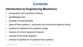
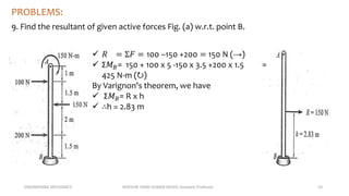
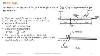
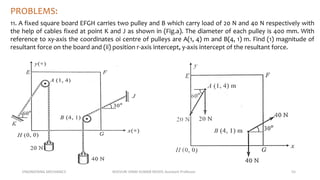
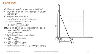
SlideShare a Scribd company logo
1 of 62
INTRODUCTION TO ENGINEERING MECHANICS
ENGINEERING
MECHANICS
KOVVURI VINAY KUMAR
REDDY
Assistant Professor
Contents
2
ENGINEERING MECHANICS KOVVURI VINAY KUMAR REDDY, Assistant Professor
Introduction to Engineering Mechanics
• Composition and resolution of forces
• parallelogram law
• principle of transmissibility
• types of force systems - concurrent and concurrent coplanar forces
• resultant of coplanar force systems couple
• moment of a force Varignon's theorem
• concept of free body diagrams
• concept of equilibrium of coplanar force systems.
ENGINEERING MECHANICS KOVVURI VINAY KUMAR REDDY, Assistant Professor 3
Mechanics is that branch of science which
deals with the behaviour of a body when the
body is at root or in motion.
AUTOMOBILES, ELECTRIC MOTORS, ROBOTS, TELEVISION, MOBILE
PHONE and etc.,
ENGINEERING MECHANICS KOVVURI VINAY KUMAR REDDY, Assistant Professor 5
Mechanics
Solid
Mechanics
Rigid Bodies
Static Dynamics
Kinematics Kinetics
Flexible
Bodies
Strength of
Materials
Theory of
Plasticity
Theory of
Elasticity
Fluid
Mechanics
Ideal Fluid
Viscous Fluid
Compressible
Fluid
ENGINEERING MECHANICS KOVVURI VINAY KUMAR REDDY, Assistant Professor 6
Static
•Statics deals with the forces on a body at rest.
Dynamics
•Dynamics deals with the forces acting on a body when the body is in motion.
•(a) Kinematics: Deals the motion of a body without considering the forces
causing the motion.
•(b) Kinetics: Deals with the relation between the forces acting on the body
and the resulting motion
ENGINEERING MECHANICS KOVVURI VINAY KUMAR REDDY, Assistant Professor 7
Rigid body: The rigid body means the body does not
deform under the action of force.
Note : Engineering Mechanics deals with Rigid body
Dynamics.
Particle: It is an object with its mass concentrated at a
point
ENGINEERING MECHANICS KOVVURI VINAY KUMAR REDDY, Assistant Professor 8
IMPORTANCE OF MECHANICS TO ENGINEERING:
1) For designing and manufacturing of various mechanical
tools and equipment's
2) For calculation and estimation of forces of bodies
while they are in use.
3) For designing and construing to dams, roads, sheds,
structure, building etc.
4) For designing a fabrication of rockets.
ENGINEERING MECHANICS KOVVURI VINAY KUMAR REDDY, Assistant Professor 9
Force: force is defined as an agency which changes or
tends to change the body at rest or in motion . Force is a
vector quantity. So we have to specify the magnitude,
direction and point of action. The unit of force is Newton.
1 N = 1 kgm
𝑠2
ENGINEERING MECHANICS KOVVURI VINAY KUMAR REDDY, Assistant Professor 10
Units and dimensions
The following units are used mostly,
1. Centimetre-Gram Second system of unit.(C.G.S)
2. Metre-kilogram-second system of units. (M.K.S)
3. International system of units. (S.I)
ENGINEERING MECHANICS KOVVURI VINAY KUMAR REDDY, Assistant Professor 11
FUNDAMENTAL UNITS
The measurement of physical quantities is one of the most important
operations in engineering. Every quantity is measured in terms of some
arbitrary, but internationally accepted units, called fundamental units.
All the physical quantities, met with in Engineering Mechanics, are
expressed in terms of three fundamental quantities, i.e.
1. length, 2. mass and 3. time.
DERIVED UNITS
Sometimes, the units are also expressed in other units (which are derived
from fundamental units) known as derived units e.g. units of area, velocity,
acceleration, pressure etc.
ENGINEERING MECHANICS KOVVURI VINAY KUMAR REDDY, Assistant Professor 12
S.I UNITS
Density 𝑘𝑔/𝑚3 Angular velocity rad/s
Force N Angular acceleration rad/s2
Pressure Pa(pascal) or 𝑁/𝑚2
Work / energy 1𝐽 = 1𝑁 − 𝑚
Power 1W= 1 𝐽
𝑆
Frequency Hz (Hertz)
Acceleration m/s2
ENGINEERING MECHANICS KOVVURI VINAY KUMAR REDDY, Assistant Professor 13
Laws of Mechanics
 Newton's laws of mechanics
1. Newton's first law of motion
2. Newton's second law of motion
3. Newton's third law of motion
 Newton's law of gravitational forces
 Law of transmissibility of forces
 Law of superposition of forces
 Parellogram law of forces
1. Newton’s First Law of Motion: It
states, “Every body continues in its state
of rest or of uniform motion in a straight
line, unless acted upon by some external
force”. This is also known as Law of
Inertia.
2. Newton’s Second Law of Motion: It
states, “The rate of change of momentum
is directly proportional to the impressed
force and takes place in the same
direction in which the force acts”.
3. Newton’s Third Law of Motion: It
states, “To every action, there is always
an equal and opposite reaction”.
ENGINEERING MECHANICS KOVVURI VINAY KUMAR REDDY, Assistant Professor 16
Law of Gravitation:
It states that two bodies will be attracted towards each other along their
connecting line with a force which is directly proportional to the product of
their masses and inversely proportional to the square of the distance
between the centres.
ENGINEERING MECHANICS KOVVURI VINAY KUMAR REDDY, Assistant Professor 17
Principle of transmissibility of forces
It states that “ if a force, acting at a point on a rigid body, is shifted to any
other point which is on the line of action of the force, the external effect of
the force on the body remains unchanged.
For example a force F is acting at point A on
a rigid body along the line of action AB. At
point B, apply two equal and opposite
forces F1 and F2 such that F1 and F2 are
collinear and equal in magnitude with F.
Now, we can transfer F1from B to A such
that F and F1 are equal and opposite and
accordingly they cancel each other. The net
result is force F2 at B. This implies that a
force acting at any point on a body may
also be considered to act at any other point
along its line of action without changing
the equilibrium of the body.
ENGINEERING MECHANICS KOVVURI VINAY KUMAR REDDY, Assistant Professor 18
SYSTEM OF FORCES
ENGINEERING MECHANICS KOVVURI VINAY KUMAR REDDY, Assistant Professor 19
SYSTEM OF FORCES
ENGINEERING MECHANICS KOVVURI VINAY KUMAR REDDY, Assistant Professor 20
SYSTEM OF FORCES
ENGINEERING MECHANICS KOVVURI VINAY KUMAR REDDY, Assistant Professor 21
RESULTANT FORCE
If a number of forces, P, Q, R ... etc. are acting simultaneously on a particle,
then it is possible to find out a single force which could replace them i.e.,
which would produce the same effect as produced by all the given forces.
This single force is called resultant force and the given forces R ... etc. are
called component forces.
COMPOSITION OF FORCES
The process of finding out the resultant force, of a number of given forces,
is called composition of forces or compounding of forces.
METHODS FOR THE RESULTANT FORCE
Though there are many methods for finding out the resultant force of a
number of given forces, yet the following are important from the subject
point of view :
1. Analytical method. 2. Method of resolution.
ENGINEERING MECHANICS KOVVURI VINAY KUMAR REDDY, Assistant Professor 22
Characteristics of Force:
ENGINEERING MECHANICS KOVVURI VINAY KUMAR REDDY, Assistant Professor 23
RESOLUTION OF A FORCE:
The process of splitting up the given force into a number of components,
without changing its effect on the body is called resolution of a force. A force
is, generally, resolved along two mutually perpendicular directions. In fact,
the resolution of a force is the reverse action of the addition of the
component vectors.
PRINCIPLE OF RESOLUTION
It states, “The algebraic sum of the resolved parts of a no. of forces, in a
given direction, is equal to the resolved part of their resultant in the same
direction.”
Note : In general, the forces are resolved in the vertical and horizontal
directions.
ENGINEERING MECHANICS KOVVURI VINAY KUMAR REDDY, Assistant Professor 24
Aditya Engineering College (A)
25
ENGINEERING MECHANICS KOVVURI VINAY KUMAR REDDY, Assistant Professor
PARALLELOGRAM LAW OF FORCES:
It states, “If two forces, acting simultaneously on a particle, be represented in magnitude and direction
by the two adjacent sides of a parallelogram ; their resultant may be represented in magnitude and
direction by the diagonal of the parallelogram, which passes through their point of intersection.”
Mathematically, resultant force,
ENGINEERING MECHANICS KOVVURI VINAY KUMAR REDDY, Assistant Professor 26
P and Q= Forces whose resultant is
required to be found out,
ɵ = Angle between the forces F1 and F2,
and
α = Angle which the resultant force makes
with one of the forces P.
ENGINEERING MECHANICS KOVVURI VINAY KUMAR REDDY, Assistant Professor 27
Triangle Law of Force:
ENGINEERING MECHANICS KOVVURI VINAY KUMAR REDDY, Assistant Professor 28
Lame‟s Theorem:
If three forces acting at a point are in equilibrium each force will be
proportional to the sine of angle between the other two forces.
ENGINEERING MECHANICS KOVVURI VINAY KUMAR REDDY, Assistant Professor 29
1. Forces R, S, T, U are collinear. Forces S and T act from left to right. Forces R and U act
from right to left. Magnitudes of the forces R, S, T, U are 40 N, 45 N, 50 N and 55 N
respectively. Find the resultant of R, S,T, U.
PROBLEMS:
Given data:
R=40 N
S=45 N
T=50 N
U=55N Resultant = -R-U+S+T
= -40-55+45+50
= 0
ENGINEERING MECHANICS KOVVURI VINAY KUMAR REDDY, Assistant Professor 30
PROBLEMS:
2. Find the resultant of the force system shown in Fig
Given data:
F1=20 KN ; Θ1=60°
F2=26 KN ; Θ2=0°
F3= 6KN ; Θ3=00°
F4=20KN ; Θ4=60°
Solution:
Resolve the given forces horizontally and calculate the algebraic total of all the
horizontal parts (Σ H) =-20cos60°+26cos0°-6cos0°-20cos60°=0
Resolve the given forces vertically and calculate the algebraic total of all the vertical
parts (Σ V)=-20sin60°+20 sin60°=0
R = √( (ΣH)^2+(ΣV)^2 )=0
ENGINEERING MECHANICS KOVVURI VINAY KUMAR REDDY, Assistant Professor 31
PROBLEMS:
3. Resolve the 100N force acting a 30° to horizontal into two component one along
horizontal and other along 120° to horizontal.
ENGINEERING MECHANICS KOVVURI VINAY KUMAR REDDY, Assistant Professor 32
PROBLEMS:
ENGINEERING MECHANICS KOVVURI VINAY KUMAR REDDY, Assistant Professor 33
PROBLEMS:
4. A block of weight 1000 N kept on inclined plane is
pushed by horizontal force 500 N as shown in Fig. Find
the sum of components of forces along x-y axis oriented
parallel and perpendicular to the incline.
ENGINEERING MECHANICS KOVVURI VINAY KUMAR REDDY, Assistant Professor 34
PROBLEMS:
ENGINEERING MECHANICS KOVVURI VINAY KUMAR REDDY, Assistant Professor 35
PROBLEMS:
5. The following forces act at a point :
(i) 20 N inclined at 30° towards North of East,
(ii) 25 N towards North,
(iii) 30 N towards North West, and
(iv) 35 N inclined at 40° towards South of West.
Find the magnitude and direction of the
resultant force.
ENGINEERING MECHANICS KOVVURI VINAY KUMAR REDDY, Assistant Professor 36
forces horizontally
ΣH = 20 cos 30° + 25 cos 90° + 30 cos 135° + 35 cos 220° N
= (20 × 0.866) + (25 × 0) + 30 (– 0.707) + 35 (– 0.766) N
= – 30.7 N
forces vertically
ΣV = 20 sin 30° + 25 sin 90° + 30 sin 135° + 35 sin 220° N
= (20 × 0.5) + (25 × 1.0) + (30 × 0.707) + 35 (– 0.6428) N
= 33.7 N
resultant force
R = √((ΣH)2 + (ΣV)2) = √((–30.7)2 + (33.7)2) = 45.6 N
Tan 𝜃 =
ΣV
ΣH
=
33.7
−30.7
=-1.098 => 𝜃=tan−1(−1.098)=47.7°
Since ΣH is negative and ΣV is positive, therefore resultant lies between 90° and 180°.
Thus actual angle of the resultant = 180° – 47.7° = 132.3°
ENGINEERING MECHANICS KOVVURI VINAY KUMAR REDDY, Assistant Professor 37
The Free Body Diagram (F.B.D.) is a sketch of the body showing all active
and reactive forces that acts on it after removing all supports with
consideration of geometrical angles and distance given.
ENGINEERING MECHANICS KOVVURI VINAY KUMAR REDDY, Assistant Professor 38
ENGINEERING MECHANICS KOVVURI VINAY KUMAR REDDY, Assistant Professor 39
ENGINEERING MECHANICS KOVVURI VINAY KUMAR REDDY, Assistant Professor 40
PROBLEMS:
6. Determine the magnitude and direction of the
resultant of forces acting on the hook shown In fig
Given data:
F1=250 N ; Θ1=35°
F2=200 N ; Θ2=20°
F3=110 N
F4=90 N ; Θ4=65°
Solution:
Resolve the given forces horizontally and calculate the algebraic total of all the
horizontal parts Σ H=250cos35°+200cos30°-90cos65°=339.957N
Resolve the given forces vertically and calculate the algebraic total of all the vertical
parts Σ V=250sin35°-200sin20°-110sin90°+90sin65=46.55N
R = √( (ΣH)2+(Σ V)2 )=343.129N
Θ=tan¯( ΣV/ΣH)=7.79°
ENGINEERING MECHANICS KOVVURI VINAY KUMAR REDDY, Assistant Professor 41
Static equilibrium
A planar structural system is in a state of static equilibrium when
the resultant of all forces and all moments is equal to zero, i.e.
ENGINEERING MECHANICS KOVVURI VINAY KUMAR REDDY, Assistant Professor 42
PROBLEMS:
7. Rope AB shown in fig(1) is 4.5m long and is connected at two points A & B at the
Same level 4m apart. A load of 1500N is suspended from a point C on the rope at 1.5m
from A. What load connected at point D on the rope, 1m from B will be Necessary to
keep the position CD level.
α β
2m
X F B
W=?
1500 N
D
C
E
A
Y
T2
T1
1500 N
C
α T2
T3
W
C β
ENGINEERING MECHANICS KOVVURI VINAY KUMAR REDDY, Assistant Professor 43
Given (Longest distance bet A&B) AB = AC+CD+DB
4.5= 1.5+CD+1
⇛ CD = 4.5-2.5 = 2m
Let us take AE=X, DF=CE=Y (to keep the position CD level), CD=EF
(shortest distance bet A&B) AB = AE+EF+FB
4 = X+2+FB
⇛ FB = 4-2-X =2-X
From ∆AEC ⇛ 𝑿𝟐 + 𝒀𝟐 = 𝟏. 𝟓𝟐
⇛ 𝑿𝟐 + 𝒀𝟐 = 𝟐. 𝟐𝟓 ……………….(i)
From ∆BFD ⇛ 𝑭𝑩𝟐
+ 𝑫𝑭𝟐
= 𝟏𝟐
⇛ 𝒀𝟐
= 𝟏 − (𝟐 − 𝑿)𝟐
⇛ 𝒀𝟐
= 𝟏 − 𝟒 + 𝟒𝑿 − 𝑿𝟐
=−𝟑 +𝟒𝑿 − 𝑿𝟐
…………(ii)
SUB (ii) in (i)
⇛ 𝑿𝟐
− 𝟑+𝟒𝑿 − 𝑿𝟐
= 𝟐. 𝟐𝟓
⇛ 4X= 𝟐. 𝟐𝟓 +𝟑
⇛ 4X= 𝟓. 𝟐𝟓
⇛ X= 𝟏. 𝟑𝟏𝟐𝟓𝒎
⇛ 𝒀𝟐 = 𝟏 − (𝟐 − 𝑿)𝟐 ⇛ Y= 𝟎. 𝟕𝟐𝟔𝟐𝒎
⇛FB =2-X=2-1.3125=0.6875m
ENGINEERING MECHANICS KOVVURI VINAY KUMAR REDDY, Assistant Professor 44
ENGINEERING MECHANICS KOVVURI VINAY KUMAR REDDY, Assistant Professor 45
PROBLEMS:
8. A sphere of mass “M” rests in a V-groove whose sides are inclined at angles α & β to
the horizontal. Another identical sphere of same mass “M” rests on the first sphere and
in contact with the side inclined at an angle α. Find the reaction RB on the lower sphere
at the point B.
C
α β
B
A W=Mg
W=Mg
D
ENGINEERING MECHANICS KOVVURI VINAY KUMAR REDDY, Assistant Professor 46
α β
B
RB
A
RA
W=Mg
W=Mg
D
RD
RC
α
α
α β
β
β
α
β
RD
RC
α
β
α
β
RB-RC
RA
W=Mg
W=Mg
ENGINEERING MECHANICS KOVVURI VINAY KUMAR REDDY, Assistant Professor 47
MOMENT OF A FORCE:
It is the turning effect produced by a force, on the body, on which it acts. The moment of
a force is equal to the product of the force and the perpendicular distance of the point,
about which the moment is required and the line of action of the force.
M = F × L (N × mm)
F = Force acting on the body, and
L = Perpendicular distance between the point, about which the moment is required
and the line of action of the force.
 clockwise moment as positive
 Anticlockwise moment as negative.
ENGINEERING MECHANICS KOVVURI VINAY KUMAR REDDY, Assistant Professor 48
VARIGNON’S PRINCIPLE OF MOMENTS (OR LAW OF MOMENTS)
It states, “If a number of coplanar forces are acting simultaneously on a particle, the
algebraic sum of the moments of all the forces about any point is equal to the moment of
their resultant force about the same point.”
ENGINEERING MECHANICS KOVVURI VINAY KUMAR REDDY, Assistant Professor 49
ENGINEERING MECHANICS KOVVURI VINAY KUMAR REDDY, Assistant Professor 50
Multiplying both sides by length OA
R x OA sin ɵ = P x OA sin ɵ1 + Q x OA sin ɵ2
But OA sin ɵ = d ,
OA sin ɵ1 = d1 and
OA sin ɵ2 = d2
=> R x d = P x d1 + Q x d2
Hence Proved.
Note: Varignon's theorem is used for determining the position of
resultant of parallel and general force system.
ENGINEERING MECHANICS KOVVURI VINAY KUMAR REDDY, Assistant Professor 51
Resultant of Parallel Force System
+𝑣𝑒 ↻/−𝑣𝑒 ↺
+𝑣𝑒 → ⬆/−𝑣𝑒 ← ⬇
ENGINEERING MECHANICS KOVVURI VINAY KUMAR REDDY, Assistant Professor 52
(i) ΣF(⬆) and ΣMO −𝑣𝑒 ↺
(ii) ΣF(⬇) and ΣMO −𝑣𝑒 ↺
(iii)ΣF(⬆) and ΣMO +𝑣𝑒 ↻
(iv)ΣF(⬇) and ΣMO(+𝑣𝑒 ↻)
ENGINEERING MECHANICS KOVVURI VINAY KUMAR REDDY, Assistant Professor 53
PROBLEMS:
9. Find the resultant of given active forces Fig. (a) w.r.t. point B.
 𝑅 = Σ𝐹 = 100 −150 +200 = 150 N (→)
 Σ𝑀𝐵= 150 + 100 x 5 -150 x 3.5 +200 x 1.5 =
425 N-m (↻)
By Varignon's theorem, we have
 Σ𝑀𝐵= R x h
 ∴h = 2.83 m
ENGINEERING MECHANICS KOVVURI VINAY KUMAR REDDY, Assistant Professor 54
PROBLEMS:
10. Replace the system of forces and couple shown in (Fig. a) by a single force couple
system at A.
 ΣFX= −100 cos 36.87° − 75 = −155 N = 155 N ( ← )
 ΣFY=−200 + 50 − 100 sin 36.87°= −210 N = 210 N ( ↓ )
 Magnitude of resultant R
R= (1552 + 2102) = 261N
 Inclination of the resultant ɵ
ɵ = tan−1 210
115
= 53.57°
 ΣMA= -50 x 2 -80 +100 sin 36.87° x 4 = 60 N-m (↻)
 The resultant of forces system is form of single force and
couple is as shown in (Fig.b) at A.
ENGINEERING MECHANICS KOVVURI VINAY KUMAR REDDY, Assistant Professor 55
PROBLEMS:
11. A fixed square board EFGH carries two pulley and B which carry load of 20 N and 40 N respectively with
the help of cables fixed at point K and J as shown in (Fig.a). The diameter of each pulley is 400 mm. With
reference to xy-axis the coordinates oi centre of pulleys are A(1, 4) m and B(4, 1) m. Find (1) magnitude of
resultant force on the board and (ii) position r-axis intercept, y-axis intercept of the resultant force.
ENGINEERING MECHANICS KOVVURI VINAY KUMAR REDDY, Assistant Professor 56
PROBLEMS:
 ΣFX= −20 cos 60° + 40 cos 30°=24.64 N( → )
 ΣFY=−20− 20 sin 60° − 40+40 sin 30° =−57.32N
=57.32N( ↓ )
 Magnitude of resultant R
R= (24.642 + 57.322) = 62.39 N
 Inclination of the resultant ɵ
ɵ = tan−1 57.32
24.64
= 66.74°
ΣMH= 20 x 1 -20 cos 60° x 4 +20 sin 60° x1 + 40 x 4
+ 40 cos 30° x l - 40 sin 30°x4
= 111.96 N-m (↻)
 By Varignon’s theorem, we have
X =
ΣMA
ΣFy
=
111.96
57.32
= 1.95 m
Y =
ΣMA
ΣFx
=
111.96
24.64
= 4.54 m
 Position of resultant w.r.t. point H (0,0) (Fig.c)
ENGINEERING MECHANICS KOVVURI VINAY KUMAR REDDY, Assistant Professor 60
PROBLEMS:
12. A uniform beam AB hinged at A is kept horizontal by
supporting and setting a 50 kN weight with the help of a string
tied at B and passing over a smooth peg at C, as shown in
(Fig.a). The beam weight is 25 kN. Find the reaction at A and C.
 Consider the F.B.D. of BEAM AB
ΣMA= 0
(50 - T)2 +25 x 3 -Tsin 36.87° x 6 = 0
T = 31.25 KN
ΣFX= 0
HA-31.25 cos 36.87° = 0
HA= 25kN (→)
ΣFY= 0
VA-(50- 7) -25 +T sin 36.87° = 0
VA= 25kN (↑)
 Consider the F.B.D. of Block D
ΣFX= 0
R + T − 50 = 0 ⇛ 𝑅 = 50 − 𝑇
 Consider the F.B.D. of Peg C
ΣFX= 0
-HC+ 31.25 cos 36.87°= 0
HC= 25kN (←)
ΣFY= 0
VC-31.25 - 31.25 sin 36.87°= 0
VC= 50kN (↑)
ENGINEERING MECHANICS KOVVURI VINAY KUMAR REDDY, Assistant Professor 61
PROBLEMS:
13. A bar AB pinned at A carries a load W= 5 kN. The cord
attached at B is passing through frictionless pulley as
shown in (Fig.a). Find the compression in the bar AB and
also the limiting value of the tension in cord when bar
approaches the vertical position.
ΣFY= 0
𝑅𝐴 sin 𝛳 +T sin 𝛽 - 5000 = 0
T sin 𝛽 = 5000 - 𝑅𝐴 sin 𝛳 .....................(i)
ΣFx= 0
𝑅𝐴 cos 𝛳 -T cos 𝛽 = 0
T cos 𝛽 = 𝑅𝐴 cos 𝛳 ..............................(ii)
Dividing Eq. (i) by Eq. (ii), we get
tan 𝛽 =
5000 − 𝑅𝐴 sin 𝛳
𝑅𝐴 cos 𝛳
.......................(iii)
Consider, ∆DBC
tan 𝛽 =
𝐶𝐷
𝐵𝐷
=
𝐴𝐶−𝐴𝐷
𝐵𝐷
................................(Iv)
ENGINEERING MECHANICS KOVVURI VINAY KUMAR REDDY, Assistant Professor 62
PROBLEMS: From Eqs. (iii) and (iv), we get
𝐴𝐶−𝐴𝐷
𝐵𝐷
=
5000 − 𝑅𝐴 sin 𝛳
𝑅𝐴 cos 𝛳
⇛
2.5−2𝑠𝑖𝑛 𝛳
2𝑐𝑜𝑠 𝛳
=
5000 − 𝑅𝐴 sin 𝛳
𝑅𝐴 cos 𝛳
⇛2.5𝑅𝐴 − 2𝑅𝐴𝑠𝑖𝑛 𝛳 =10000 - 2𝑅𝐴 sin 𝛳
⇛ 𝑅𝐴 = 4000 N
While obtaining RA in the above expression, the
inclination of bar AB is not influencing the
solution. So we concluded that reaction at A
remains 4000 N for all values of 0 as shown in
(Fig.c).
Consider the F.B.D. of Bar AB in vertical position
By equilibrium condition
∑𝐹𝑌 =0 ⇛ 𝑅𝐴+T – 5000 = 0
⇛ T = 5000 - 4000
⇛ T = 1000N

More Related Content

What's hot

6161103 2.6 addition and subtraction of cartesian vectors
6161103 2.6 addition and subtraction of cartesian vectors6161103 2.6 addition and subtraction of cartesian vectors
6161103 2.6 addition and subtraction of cartesian vectors
etcenterrbru
 
6161103 4.6 moment of a couple
6161103 4.6 moment of a couple6161103 4.6 moment of a couple
6161103 4.6 moment of a couple
etcenterrbru
 
Ordinary differential equations
Ordinary differential equationsOrdinary differential equations
Ordinary differential equations
Ahmed Haider
 

What's hot (20)

Stresses and strains (Part 1)
Stresses and strains (Part 1)Stresses and strains (Part 1)
Stresses and strains (Part 1)
 
1.4 - Forces in Space.pptx
1.4 - Forces in Space.pptx1.4 - Forces in Space.pptx
1.4 - Forces in Space.pptx
 
Introduction to mechanics
Introduction to mechanicsIntroduction to mechanics
Introduction to mechanics
 
Introduction of Partial Differential Equations
Introduction of Partial Differential EquationsIntroduction of Partial Differential Equations
Introduction of Partial Differential Equations
 
Handbook to ssc je mechanical
Handbook to ssc je mechanical Handbook to ssc je mechanical
Handbook to ssc je mechanical
 
Unit 5 Friction
Unit 5 FrictionUnit 5 Friction
Unit 5 Friction
 
6161103 2.6 addition and subtraction of cartesian vectors
6161103 2.6 addition and subtraction of cartesian vectors6161103 2.6 addition and subtraction of cartesian vectors
6161103 2.6 addition and subtraction of cartesian vectors
 
Higher Order Differential Equation
Higher Order Differential EquationHigher Order Differential Equation
Higher Order Differential Equation
 
6161103 4.6 moment of a couple
6161103 4.6 moment of a couple6161103 4.6 moment of a couple
6161103 4.6 moment of a couple
 
Finite element method
Finite element methodFinite element method
Finite element method
 
application of differential equation and multiple integral
application of differential equation and multiple integralapplication of differential equation and multiple integral
application of differential equation and multiple integral
 
Application of-differential-equation-in-real-life
Application of-differential-equation-in-real-lifeApplication of-differential-equation-in-real-life
Application of-differential-equation-in-real-life
 
Taylor series
Taylor seriesTaylor series
Taylor series
 
APPLICATIONS OF DIFFERENTIAL EQUATIONS-ZBJ
APPLICATIONS OF DIFFERENTIAL EQUATIONS-ZBJAPPLICATIONS OF DIFFERENTIAL EQUATIONS-ZBJ
APPLICATIONS OF DIFFERENTIAL EQUATIONS-ZBJ
 
Variational Principle
Variational PrincipleVariational Principle
Variational Principle
 
Basic concept of Engineering Mechanics
Basic concept of Engineering MechanicsBasic concept of Engineering Mechanics
Basic concept of Engineering Mechanics
 
Ordinary differential equations
Ordinary differential equationsOrdinary differential equations
Ordinary differential equations
 
Laplace periodic function with graph
Laplace periodic function with graphLaplace periodic function with graph
Laplace periodic function with graph
 
Vector multiplication dot product
Vector multiplication   dot productVector multiplication   dot product
Vector multiplication dot product
 
Laplace Transformation & Its Application
Laplace Transformation & Its ApplicationLaplace Transformation & Its Application
Laplace Transformation & Its Application
 

Similar to INTRODUCTION TO ENGINEERING MECHANICS

L01 03
L01 03L01 03
L01 03
hitusp
 

Similar to INTRODUCTION TO ENGINEERING MECHANICS (20)

Unit 1 ( introduction basic)
Unit 1 ( introduction basic)Unit 1 ( introduction basic)
Unit 1 ( introduction basic)
 
ME3351 ENGG. MECHANICS MLM.pdf
ME3351 ENGG. MECHANICS MLM.pdfME3351 ENGG. MECHANICS MLM.pdf
ME3351 ENGG. MECHANICS MLM.pdf
 
THEORY OF STRUCTURES-I [B. ARCH.]
THEORY OF STRUCTURES-I [B. ARCH.]THEORY OF STRUCTURES-I [B. ARCH.]
THEORY OF STRUCTURES-I [B. ARCH.]
 
L01 03
L01 03L01 03
L01 03
 
L01 03
L01 03L01 03
L01 03
 
em ppt.pdf
em ppt.pdfem ppt.pdf
em ppt.pdf
 
DYNAMICS OF MACHINES.ppt
DYNAMICS OF MACHINES.pptDYNAMICS OF MACHINES.ppt
DYNAMICS OF MACHINES.ppt
 
Statics of particle
Statics of particle Statics of particle
Statics of particle
 
1. Resolution and composition of forces REV (2).ppt
1. Resolution and composition of forces REV (2).ppt1. Resolution and composition of forces REV (2).ppt
1. Resolution and composition of forces REV (2).ppt
 
Introduction
IntroductionIntroduction
Introduction
 
module 1 (Mechanics)
module 1 (Mechanics)module 1 (Mechanics)
module 1 (Mechanics)
 
KTU BE 100 Engineering Mechanics
KTU BE 100 Engineering MechanicsKTU BE 100 Engineering Mechanics
KTU BE 100 Engineering Mechanics
 
Applied mechanics
Applied mechanicsApplied mechanics
Applied mechanics
 
Introduction to Engineering Mechanics
Introduction to Engineering MechanicsIntroduction to Engineering Mechanics
Introduction to Engineering Mechanics
 
Module 3.pptx
Module 3.pptxModule 3.pptx
Module 3.pptx
 
APPLIED MECHANICS (1).ppt
APPLIED MECHANICS (1).pptAPPLIED MECHANICS (1).ppt
APPLIED MECHANICS (1).ppt
 
APPLIED MECHANICS online lecture.pptx
APPLIED MECHANICS online lecture.pptxAPPLIED MECHANICS online lecture.pptx
APPLIED MECHANICS online lecture.pptx
 
Engineering Mechanics.pptx
Engineering Mechanics.pptxEngineering Mechanics.pptx
Engineering Mechanics.pptx
 
001module1 Engineering Machanics 2019.pdf
001module1 Engineering Machanics 2019.pdf001module1 Engineering Machanics 2019.pdf
001module1 Engineering Machanics 2019.pdf
 
engineering mechanics
engineering mechanicsengineering mechanics
engineering mechanics
 

Recently uploaded

Artificial intelligence presentation2-171219131633.pdf
Artificial intelligence presentation2-171219131633.pdfArtificial intelligence presentation2-171219131633.pdf
Artificial intelligence presentation2-171219131633.pdf
Kira Dess
 
Tembisa Central Terminating Pills +27838792658 PHOMOLONG Top Abortion Pills F...
Tembisa Central Terminating Pills +27838792658 PHOMOLONG Top Abortion Pills F...Tembisa Central Terminating Pills +27838792658 PHOMOLONG Top Abortion Pills F...
Tembisa Central Terminating Pills +27838792658 PHOMOLONG Top Abortion Pills F...
drjose256
 

Recently uploaded (20)

analog-vs-digital-communication (concept of analog and digital).pptx
analog-vs-digital-communication (concept of analog and digital).pptxanalog-vs-digital-communication (concept of analog and digital).pptx
analog-vs-digital-communication (concept of analog and digital).pptx
 
Diploma Engineering Drawing Qp-2024 Ece .pdf
Diploma Engineering Drawing Qp-2024 Ece .pdfDiploma Engineering Drawing Qp-2024 Ece .pdf
Diploma Engineering Drawing Qp-2024 Ece .pdf
 
Artificial intelligence presentation2-171219131633.pdf
Artificial intelligence presentation2-171219131633.pdfArtificial intelligence presentation2-171219131633.pdf
Artificial intelligence presentation2-171219131633.pdf
 
Insurance management system project report.pdf
Insurance management system project report.pdfInsurance management system project report.pdf
Insurance management system project report.pdf
 
Dynamo Scripts for Task IDs and Space Naming.pptx
Dynamo Scripts for Task IDs and Space Naming.pptxDynamo Scripts for Task IDs and Space Naming.pptx
Dynamo Scripts for Task IDs and Space Naming.pptx
 
Instruct Nirmaana 24-Smart and Lean Construction Through Technology.pdf
Instruct Nirmaana 24-Smart and Lean Construction Through Technology.pdfInstruct Nirmaana 24-Smart and Lean Construction Through Technology.pdf
Instruct Nirmaana 24-Smart and Lean Construction Through Technology.pdf
 
Tembisa Central Terminating Pills +27838792658 PHOMOLONG Top Abortion Pills F...
Tembisa Central Terminating Pills +27838792658 PHOMOLONG Top Abortion Pills F...Tembisa Central Terminating Pills +27838792658 PHOMOLONG Top Abortion Pills F...
Tembisa Central Terminating Pills +27838792658 PHOMOLONG Top Abortion Pills F...
 
15-Minute City: A Completely New Horizon
15-Minute City: A Completely New Horizon15-Minute City: A Completely New Horizon
15-Minute City: A Completely New Horizon
 
litvinenko_Henry_Intrusion_Hong-Kong_2024.pdf
litvinenko_Henry_Intrusion_Hong-Kong_2024.pdflitvinenko_Henry_Intrusion_Hong-Kong_2024.pdf
litvinenko_Henry_Intrusion_Hong-Kong_2024.pdf
 
Passive Air Cooling System and Solar Water Heater.ppt
Passive Air Cooling System and Solar Water Heater.pptPassive Air Cooling System and Solar Water Heater.ppt
Passive Air Cooling System and Solar Water Heater.ppt
 
Intro to Design (for Engineers) at Sydney Uni
Intro to Design (for Engineers) at Sydney UniIntro to Design (for Engineers) at Sydney Uni
Intro to Design (for Engineers) at Sydney Uni
 
The Entity-Relationship Model(ER Diagram).pptx
The Entity-Relationship Model(ER Diagram).pptxThe Entity-Relationship Model(ER Diagram).pptx
The Entity-Relationship Model(ER Diagram).pptx
 
Interfacing Analog to Digital Data Converters ee3404.pdf
Interfacing Analog to Digital Data Converters ee3404.pdfInterfacing Analog to Digital Data Converters ee3404.pdf
Interfacing Analog to Digital Data Converters ee3404.pdf
 
NEWLETTER FRANCE HELICES/ SDS SURFACE DRIVES - MAY 2024
NEWLETTER FRANCE HELICES/ SDS SURFACE DRIVES - MAY 2024NEWLETTER FRANCE HELICES/ SDS SURFACE DRIVES - MAY 2024
NEWLETTER FRANCE HELICES/ SDS SURFACE DRIVES - MAY 2024
 
Theory of Time 2024 (Universal Theory for Everything)
Theory of Time 2024 (Universal Theory for Everything)Theory of Time 2024 (Universal Theory for Everything)
Theory of Time 2024 (Universal Theory for Everything)
 
Filters for Electromagnetic Compatibility Applications
Filters for Electromagnetic Compatibility ApplicationsFilters for Electromagnetic Compatibility Applications
Filters for Electromagnetic Compatibility Applications
 
Research Methodolgy & Intellectual Property Rights Series 1
Research Methodolgy & Intellectual Property Rights Series 1Research Methodolgy & Intellectual Property Rights Series 1
Research Methodolgy & Intellectual Property Rights Series 1
 
8th International Conference on Soft Computing, Mathematics and Control (SMC ...
8th International Conference on Soft Computing, Mathematics and Control (SMC ...8th International Conference on Soft Computing, Mathematics and Control (SMC ...
8th International Conference on Soft Computing, Mathematics and Control (SMC ...
 
engineering chemistry power point presentation
engineering chemistry  power point presentationengineering chemistry  power point presentation
engineering chemistry power point presentation
 
Adsorption (mass transfer operations 2) ppt
Adsorption (mass transfer operations 2) pptAdsorption (mass transfer operations 2) ppt
Adsorption (mass transfer operations 2) ppt
 

INTRODUCTION TO ENGINEERING MECHANICS

  • 1. INTRODUCTION TO ENGINEERING MECHANICS ENGINEERING MECHANICS KOVVURI VINAY KUMAR REDDY Assistant Professor
  • 2. Contents 2 ENGINEERING MECHANICS KOVVURI VINAY KUMAR REDDY, Assistant Professor Introduction to Engineering Mechanics • Composition and resolution of forces • parallelogram law • principle of transmissibility • types of force systems - concurrent and concurrent coplanar forces • resultant of coplanar force systems couple • moment of a force Varignon's theorem • concept of free body diagrams • concept of equilibrium of coplanar force systems.
  • 3. ENGINEERING MECHANICS KOVVURI VINAY KUMAR REDDY, Assistant Professor 3 Mechanics is that branch of science which deals with the behaviour of a body when the body is at root or in motion. AUTOMOBILES, ELECTRIC MOTORS, ROBOTS, TELEVISION, MOBILE PHONE and etc.,
  • 4.
  • 5. ENGINEERING MECHANICS KOVVURI VINAY KUMAR REDDY, Assistant Professor 5 Mechanics Solid Mechanics Rigid Bodies Static Dynamics Kinematics Kinetics Flexible Bodies Strength of Materials Theory of Plasticity Theory of Elasticity Fluid Mechanics Ideal Fluid Viscous Fluid Compressible Fluid
  • 6. ENGINEERING MECHANICS KOVVURI VINAY KUMAR REDDY, Assistant Professor 6 Static •Statics deals with the forces on a body at rest. Dynamics •Dynamics deals with the forces acting on a body when the body is in motion. •(a) Kinematics: Deals the motion of a body without considering the forces causing the motion. •(b) Kinetics: Deals with the relation between the forces acting on the body and the resulting motion
  • 7. ENGINEERING MECHANICS KOVVURI VINAY KUMAR REDDY, Assistant Professor 7 Rigid body: The rigid body means the body does not deform under the action of force. Note : Engineering Mechanics deals with Rigid body Dynamics. Particle: It is an object with its mass concentrated at a point
  • 8. ENGINEERING MECHANICS KOVVURI VINAY KUMAR REDDY, Assistant Professor 8 IMPORTANCE OF MECHANICS TO ENGINEERING: 1) For designing and manufacturing of various mechanical tools and equipment's 2) For calculation and estimation of forces of bodies while they are in use. 3) For designing and construing to dams, roads, sheds, structure, building etc. 4) For designing a fabrication of rockets.
  • 9. ENGINEERING MECHANICS KOVVURI VINAY KUMAR REDDY, Assistant Professor 9 Force: force is defined as an agency which changes or tends to change the body at rest or in motion . Force is a vector quantity. So we have to specify the magnitude, direction and point of action. The unit of force is Newton. 1 N = 1 kgm 𝑠2
  • 10. ENGINEERING MECHANICS KOVVURI VINAY KUMAR REDDY, Assistant Professor 10 Units and dimensions The following units are used mostly, 1. Centimetre-Gram Second system of unit.(C.G.S) 2. Metre-kilogram-second system of units. (M.K.S) 3. International system of units. (S.I)
  • 11. ENGINEERING MECHANICS KOVVURI VINAY KUMAR REDDY, Assistant Professor 11 FUNDAMENTAL UNITS The measurement of physical quantities is one of the most important operations in engineering. Every quantity is measured in terms of some arbitrary, but internationally accepted units, called fundamental units. All the physical quantities, met with in Engineering Mechanics, are expressed in terms of three fundamental quantities, i.e. 1. length, 2. mass and 3. time. DERIVED UNITS Sometimes, the units are also expressed in other units (which are derived from fundamental units) known as derived units e.g. units of area, velocity, acceleration, pressure etc.
  • 12. ENGINEERING MECHANICS KOVVURI VINAY KUMAR REDDY, Assistant Professor 12 S.I UNITS Density 𝑘𝑔/𝑚3 Angular velocity rad/s Force N Angular acceleration rad/s2 Pressure Pa(pascal) or 𝑁/𝑚2 Work / energy 1𝐽 = 1𝑁 − 𝑚 Power 1W= 1 𝐽 𝑆 Frequency Hz (Hertz) Acceleration m/s2
  • 13. ENGINEERING MECHANICS KOVVURI VINAY KUMAR REDDY, Assistant Professor 13
  • 14. Laws of Mechanics  Newton's laws of mechanics 1. Newton's first law of motion 2. Newton's second law of motion 3. Newton's third law of motion  Newton's law of gravitational forces  Law of transmissibility of forces  Law of superposition of forces  Parellogram law of forces
  • 15. 1. Newton’s First Law of Motion: It states, “Every body continues in its state of rest or of uniform motion in a straight line, unless acted upon by some external force”. This is also known as Law of Inertia. 2. Newton’s Second Law of Motion: It states, “The rate of change of momentum is directly proportional to the impressed force and takes place in the same direction in which the force acts”. 3. Newton’s Third Law of Motion: It states, “To every action, there is always an equal and opposite reaction”.
  • 16. ENGINEERING MECHANICS KOVVURI VINAY KUMAR REDDY, Assistant Professor 16 Law of Gravitation: It states that two bodies will be attracted towards each other along their connecting line with a force which is directly proportional to the product of their masses and inversely proportional to the square of the distance between the centres.
  • 17. ENGINEERING MECHANICS KOVVURI VINAY KUMAR REDDY, Assistant Professor 17 Principle of transmissibility of forces It states that “ if a force, acting at a point on a rigid body, is shifted to any other point which is on the line of action of the force, the external effect of the force on the body remains unchanged. For example a force F is acting at point A on a rigid body along the line of action AB. At point B, apply two equal and opposite forces F1 and F2 such that F1 and F2 are collinear and equal in magnitude with F. Now, we can transfer F1from B to A such that F and F1 are equal and opposite and accordingly they cancel each other. The net result is force F2 at B. This implies that a force acting at any point on a body may also be considered to act at any other point along its line of action without changing the equilibrium of the body.
  • 18. ENGINEERING MECHANICS KOVVURI VINAY KUMAR REDDY, Assistant Professor 18 SYSTEM OF FORCES
  • 19. ENGINEERING MECHANICS KOVVURI VINAY KUMAR REDDY, Assistant Professor 19 SYSTEM OF FORCES
  • 20. ENGINEERING MECHANICS KOVVURI VINAY KUMAR REDDY, Assistant Professor 20 SYSTEM OF FORCES
  • 21. ENGINEERING MECHANICS KOVVURI VINAY KUMAR REDDY, Assistant Professor 21 RESULTANT FORCE If a number of forces, P, Q, R ... etc. are acting simultaneously on a particle, then it is possible to find out a single force which could replace them i.e., which would produce the same effect as produced by all the given forces. This single force is called resultant force and the given forces R ... etc. are called component forces. COMPOSITION OF FORCES The process of finding out the resultant force, of a number of given forces, is called composition of forces or compounding of forces. METHODS FOR THE RESULTANT FORCE Though there are many methods for finding out the resultant force of a number of given forces, yet the following are important from the subject point of view : 1. Analytical method. 2. Method of resolution.
  • 22. ENGINEERING MECHANICS KOVVURI VINAY KUMAR REDDY, Assistant Professor 22 Characteristics of Force:
  • 23. ENGINEERING MECHANICS KOVVURI VINAY KUMAR REDDY, Assistant Professor 23 RESOLUTION OF A FORCE: The process of splitting up the given force into a number of components, without changing its effect on the body is called resolution of a force. A force is, generally, resolved along two mutually perpendicular directions. In fact, the resolution of a force is the reverse action of the addition of the component vectors. PRINCIPLE OF RESOLUTION It states, “The algebraic sum of the resolved parts of a no. of forces, in a given direction, is equal to the resolved part of their resultant in the same direction.” Note : In general, the forces are resolved in the vertical and horizontal directions.
  • 24. ENGINEERING MECHANICS KOVVURI VINAY KUMAR REDDY, Assistant Professor 24
  • 25. Aditya Engineering College (A) 25 ENGINEERING MECHANICS KOVVURI VINAY KUMAR REDDY, Assistant Professor PARALLELOGRAM LAW OF FORCES: It states, “If two forces, acting simultaneously on a particle, be represented in magnitude and direction by the two adjacent sides of a parallelogram ; their resultant may be represented in magnitude and direction by the diagonal of the parallelogram, which passes through their point of intersection.” Mathematically, resultant force,
  • 26. ENGINEERING MECHANICS KOVVURI VINAY KUMAR REDDY, Assistant Professor 26 P and Q= Forces whose resultant is required to be found out, ɵ = Angle between the forces F1 and F2, and α = Angle which the resultant force makes with one of the forces P.
  • 27. ENGINEERING MECHANICS KOVVURI VINAY KUMAR REDDY, Assistant Professor 27 Triangle Law of Force:
  • 28. ENGINEERING MECHANICS KOVVURI VINAY KUMAR REDDY, Assistant Professor 28 Lame‟s Theorem: If three forces acting at a point are in equilibrium each force will be proportional to the sine of angle between the other two forces.
  • 29. ENGINEERING MECHANICS KOVVURI VINAY KUMAR REDDY, Assistant Professor 29 1. Forces R, S, T, U are collinear. Forces S and T act from left to right. Forces R and U act from right to left. Magnitudes of the forces R, S, T, U are 40 N, 45 N, 50 N and 55 N respectively. Find the resultant of R, S,T, U. PROBLEMS: Given data: R=40 N S=45 N T=50 N U=55N Resultant = -R-U+S+T = -40-55+45+50 = 0
  • 30. ENGINEERING MECHANICS KOVVURI VINAY KUMAR REDDY, Assistant Professor 30 PROBLEMS: 2. Find the resultant of the force system shown in Fig Given data: F1=20 KN ; Θ1=60° F2=26 KN ; Θ2=0° F3= 6KN ; Θ3=00° F4=20KN ; Θ4=60° Solution: Resolve the given forces horizontally and calculate the algebraic total of all the horizontal parts (Σ H) =-20cos60°+26cos0°-6cos0°-20cos60°=0 Resolve the given forces vertically and calculate the algebraic total of all the vertical parts (Σ V)=-20sin60°+20 sin60°=0 R = √( (ΣH)^2+(ΣV)^2 )=0
  • 31. ENGINEERING MECHANICS KOVVURI VINAY KUMAR REDDY, Assistant Professor 31 PROBLEMS: 3. Resolve the 100N force acting a 30° to horizontal into two component one along horizontal and other along 120° to horizontal.
  • 32. ENGINEERING MECHANICS KOVVURI VINAY KUMAR REDDY, Assistant Professor 32 PROBLEMS:
  • 33. ENGINEERING MECHANICS KOVVURI VINAY KUMAR REDDY, Assistant Professor 33 PROBLEMS: 4. A block of weight 1000 N kept on inclined plane is pushed by horizontal force 500 N as shown in Fig. Find the sum of components of forces along x-y axis oriented parallel and perpendicular to the incline.
  • 34. ENGINEERING MECHANICS KOVVURI VINAY KUMAR REDDY, Assistant Professor 34 PROBLEMS:
  • 35. ENGINEERING MECHANICS KOVVURI VINAY KUMAR REDDY, Assistant Professor 35 PROBLEMS: 5. The following forces act at a point : (i) 20 N inclined at 30° towards North of East, (ii) 25 N towards North, (iii) 30 N towards North West, and (iv) 35 N inclined at 40° towards South of West. Find the magnitude and direction of the resultant force.
  • 36. ENGINEERING MECHANICS KOVVURI VINAY KUMAR REDDY, Assistant Professor 36 forces horizontally ΣH = 20 cos 30° + 25 cos 90° + 30 cos 135° + 35 cos 220° N = (20 × 0.866) + (25 × 0) + 30 (– 0.707) + 35 (– 0.766) N = – 30.7 N forces vertically ΣV = 20 sin 30° + 25 sin 90° + 30 sin 135° + 35 sin 220° N = (20 × 0.5) + (25 × 1.0) + (30 × 0.707) + 35 (– 0.6428) N = 33.7 N resultant force R = √((ΣH)2 + (ΣV)2) = √((–30.7)2 + (33.7)2) = 45.6 N Tan 𝜃 = ΣV ΣH = 33.7 −30.7 =-1.098 => 𝜃=tan−1(−1.098)=47.7° Since ΣH is negative and ΣV is positive, therefore resultant lies between 90° and 180°. Thus actual angle of the resultant = 180° – 47.7° = 132.3°
  • 37. ENGINEERING MECHANICS KOVVURI VINAY KUMAR REDDY, Assistant Professor 37 The Free Body Diagram (F.B.D.) is a sketch of the body showing all active and reactive forces that acts on it after removing all supports with consideration of geometrical angles and distance given.
  • 38. ENGINEERING MECHANICS KOVVURI VINAY KUMAR REDDY, Assistant Professor 38
  • 39. ENGINEERING MECHANICS KOVVURI VINAY KUMAR REDDY, Assistant Professor 39
  • 40. ENGINEERING MECHANICS KOVVURI VINAY KUMAR REDDY, Assistant Professor 40 PROBLEMS: 6. Determine the magnitude and direction of the resultant of forces acting on the hook shown In fig Given data: F1=250 N ; Θ1=35° F2=200 N ; Θ2=20° F3=110 N F4=90 N ; Θ4=65° Solution: Resolve the given forces horizontally and calculate the algebraic total of all the horizontal parts Σ H=250cos35°+200cos30°-90cos65°=339.957N Resolve the given forces vertically and calculate the algebraic total of all the vertical parts Σ V=250sin35°-200sin20°-110sin90°+90sin65=46.55N R = √( (ΣH)2+(Σ V)2 )=343.129N Θ=tan¯( ΣV/ΣH)=7.79°
  • 41. ENGINEERING MECHANICS KOVVURI VINAY KUMAR REDDY, Assistant Professor 41 Static equilibrium A planar structural system is in a state of static equilibrium when the resultant of all forces and all moments is equal to zero, i.e.
  • 42. ENGINEERING MECHANICS KOVVURI VINAY KUMAR REDDY, Assistant Professor 42 PROBLEMS: 7. Rope AB shown in fig(1) is 4.5m long and is connected at two points A & B at the Same level 4m apart. A load of 1500N is suspended from a point C on the rope at 1.5m from A. What load connected at point D on the rope, 1m from B will be Necessary to keep the position CD level. α β 2m X F B W=? 1500 N D C E A Y T2 T1 1500 N C α T2 T3 W C β
  • 43. ENGINEERING MECHANICS KOVVURI VINAY KUMAR REDDY, Assistant Professor 43 Given (Longest distance bet A&B) AB = AC+CD+DB 4.5= 1.5+CD+1 ⇛ CD = 4.5-2.5 = 2m Let us take AE=X, DF=CE=Y (to keep the position CD level), CD=EF (shortest distance bet A&B) AB = AE+EF+FB 4 = X+2+FB ⇛ FB = 4-2-X =2-X From ∆AEC ⇛ 𝑿𝟐 + 𝒀𝟐 = 𝟏. 𝟓𝟐 ⇛ 𝑿𝟐 + 𝒀𝟐 = 𝟐. 𝟐𝟓 ……………….(i) From ∆BFD ⇛ 𝑭𝑩𝟐 + 𝑫𝑭𝟐 = 𝟏𝟐 ⇛ 𝒀𝟐 = 𝟏 − (𝟐 − 𝑿)𝟐 ⇛ 𝒀𝟐 = 𝟏 − 𝟒 + 𝟒𝑿 − 𝑿𝟐 =−𝟑 +𝟒𝑿 − 𝑿𝟐 …………(ii) SUB (ii) in (i) ⇛ 𝑿𝟐 − 𝟑+𝟒𝑿 − 𝑿𝟐 = 𝟐. 𝟐𝟓 ⇛ 4X= 𝟐. 𝟐𝟓 +𝟑 ⇛ 4X= 𝟓. 𝟐𝟓 ⇛ X= 𝟏. 𝟑𝟏𝟐𝟓𝒎 ⇛ 𝒀𝟐 = 𝟏 − (𝟐 − 𝑿)𝟐 ⇛ Y= 𝟎. 𝟕𝟐𝟔𝟐𝒎 ⇛FB =2-X=2-1.3125=0.6875m
  • 44. ENGINEERING MECHANICS KOVVURI VINAY KUMAR REDDY, Assistant Professor 44
  • 45. ENGINEERING MECHANICS KOVVURI VINAY KUMAR REDDY, Assistant Professor 45 PROBLEMS: 8. A sphere of mass “M” rests in a V-groove whose sides are inclined at angles α & β to the horizontal. Another identical sphere of same mass “M” rests on the first sphere and in contact with the side inclined at an angle α. Find the reaction RB on the lower sphere at the point B. C α β B A W=Mg W=Mg D
  • 46. ENGINEERING MECHANICS KOVVURI VINAY KUMAR REDDY, Assistant Professor 46 α β B RB A RA W=Mg W=Mg D RD RC α α α β β β α β RD RC α β α β RB-RC RA W=Mg W=Mg
  • 47. ENGINEERING MECHANICS KOVVURI VINAY KUMAR REDDY, Assistant Professor 47 MOMENT OF A FORCE: It is the turning effect produced by a force, on the body, on which it acts. The moment of a force is equal to the product of the force and the perpendicular distance of the point, about which the moment is required and the line of action of the force. M = F × L (N × mm) F = Force acting on the body, and L = Perpendicular distance between the point, about which the moment is required and the line of action of the force.  clockwise moment as positive  Anticlockwise moment as negative.
  • 48. ENGINEERING MECHANICS KOVVURI VINAY KUMAR REDDY, Assistant Professor 48 VARIGNON’S PRINCIPLE OF MOMENTS (OR LAW OF MOMENTS) It states, “If a number of coplanar forces are acting simultaneously on a particle, the algebraic sum of the moments of all the forces about any point is equal to the moment of their resultant force about the same point.”
  • 49. ENGINEERING MECHANICS KOVVURI VINAY KUMAR REDDY, Assistant Professor 49
  • 50. ENGINEERING MECHANICS KOVVURI VINAY KUMAR REDDY, Assistant Professor 50 Multiplying both sides by length OA R x OA sin ɵ = P x OA sin ɵ1 + Q x OA sin ɵ2 But OA sin ɵ = d , OA sin ɵ1 = d1 and OA sin ɵ2 = d2 => R x d = P x d1 + Q x d2 Hence Proved. Note: Varignon's theorem is used for determining the position of resultant of parallel and general force system.
  • 51. ENGINEERING MECHANICS KOVVURI VINAY KUMAR REDDY, Assistant Professor 51 Resultant of Parallel Force System +𝑣𝑒 ↻/−𝑣𝑒 ↺ +𝑣𝑒 → ⬆/−𝑣𝑒 ← ⬇
  • 52. ENGINEERING MECHANICS KOVVURI VINAY KUMAR REDDY, Assistant Professor 52 (i) ΣF(⬆) and ΣMO −𝑣𝑒 ↺ (ii) ΣF(⬇) and ΣMO −𝑣𝑒 ↺ (iii)ΣF(⬆) and ΣMO +𝑣𝑒 ↻ (iv)ΣF(⬇) and ΣMO(+𝑣𝑒 ↻)
  • 53. ENGINEERING MECHANICS KOVVURI VINAY KUMAR REDDY, Assistant Professor 53 PROBLEMS: 9. Find the resultant of given active forces Fig. (a) w.r.t. point B.  𝑅 = Σ𝐹 = 100 −150 +200 = 150 N (→)  Σ𝑀𝐵= 150 + 100 x 5 -150 x 3.5 +200 x 1.5 = 425 N-m (↻) By Varignon's theorem, we have  Σ𝑀𝐵= R x h  ∴h = 2.83 m
  • 54. ENGINEERING MECHANICS KOVVURI VINAY KUMAR REDDY, Assistant Professor 54 PROBLEMS: 10. Replace the system of forces and couple shown in (Fig. a) by a single force couple system at A.  ΣFX= −100 cos 36.87° − 75 = −155 N = 155 N ( ← )  ΣFY=−200 + 50 − 100 sin 36.87°= −210 N = 210 N ( ↓ )  Magnitude of resultant R R= (1552 + 2102) = 261N  Inclination of the resultant ɵ ɵ = tan−1 210 115 = 53.57°  ΣMA= -50 x 2 -80 +100 sin 36.87° x 4 = 60 N-m (↻)  The resultant of forces system is form of single force and couple is as shown in (Fig.b) at A.
  • 55. ENGINEERING MECHANICS KOVVURI VINAY KUMAR REDDY, Assistant Professor 55 PROBLEMS: 11. A fixed square board EFGH carries two pulley and B which carry load of 20 N and 40 N respectively with the help of cables fixed at point K and J as shown in (Fig.a). The diameter of each pulley is 400 mm. With reference to xy-axis the coordinates oi centre of pulleys are A(1, 4) m and B(4, 1) m. Find (1) magnitude of resultant force on the board and (ii) position r-axis intercept, y-axis intercept of the resultant force.
  • 56. ENGINEERING MECHANICS KOVVURI VINAY KUMAR REDDY, Assistant Professor 56 PROBLEMS:  ΣFX= −20 cos 60° + 40 cos 30°=24.64 N( → )  ΣFY=−20− 20 sin 60° − 40+40 sin 30° =−57.32N =57.32N( ↓ )  Magnitude of resultant R R= (24.642 + 57.322) = 62.39 N  Inclination of the resultant ɵ ɵ = tan−1 57.32 24.64 = 66.74° ΣMH= 20 x 1 -20 cos 60° x 4 +20 sin 60° x1 + 40 x 4 + 40 cos 30° x l - 40 sin 30°x4 = 111.96 N-m (↻)  By Varignon’s theorem, we have X = ΣMA ΣFy = 111.96 57.32 = 1.95 m Y = ΣMA ΣFx = 111.96 24.64 = 4.54 m  Position of resultant w.r.t. point H (0,0) (Fig.c)
  • 57.
  • 58.
  • 59.
  • 60. ENGINEERING MECHANICS KOVVURI VINAY KUMAR REDDY, Assistant Professor 60 PROBLEMS: 12. A uniform beam AB hinged at A is kept horizontal by supporting and setting a 50 kN weight with the help of a string tied at B and passing over a smooth peg at C, as shown in (Fig.a). The beam weight is 25 kN. Find the reaction at A and C.  Consider the F.B.D. of BEAM AB ΣMA= 0 (50 - T)2 +25 x 3 -Tsin 36.87° x 6 = 0 T = 31.25 KN ΣFX= 0 HA-31.25 cos 36.87° = 0 HA= 25kN (→) ΣFY= 0 VA-(50- 7) -25 +T sin 36.87° = 0 VA= 25kN (↑)  Consider the F.B.D. of Block D ΣFX= 0 R + T − 50 = 0 ⇛ 𝑅 = 50 − 𝑇  Consider the F.B.D. of Peg C ΣFX= 0 -HC+ 31.25 cos 36.87°= 0 HC= 25kN (←) ΣFY= 0 VC-31.25 - 31.25 sin 36.87°= 0 VC= 50kN (↑)
  • 61. ENGINEERING MECHANICS KOVVURI VINAY KUMAR REDDY, Assistant Professor 61 PROBLEMS: 13. A bar AB pinned at A carries a load W= 5 kN. The cord attached at B is passing through frictionless pulley as shown in (Fig.a). Find the compression in the bar AB and also the limiting value of the tension in cord when bar approaches the vertical position. ΣFY= 0 𝑅𝐴 sin 𝛳 +T sin 𝛽 - 5000 = 0 T sin 𝛽 = 5000 - 𝑅𝐴 sin 𝛳 .....................(i) ΣFx= 0 𝑅𝐴 cos 𝛳 -T cos 𝛽 = 0 T cos 𝛽 = 𝑅𝐴 cos 𝛳 ..............................(ii) Dividing Eq. (i) by Eq. (ii), we get tan 𝛽 = 5000 − 𝑅𝐴 sin 𝛳 𝑅𝐴 cos 𝛳 .......................(iii) Consider, ∆DBC tan 𝛽 = 𝐶𝐷 𝐵𝐷 = 𝐴𝐶−𝐴𝐷 𝐵𝐷 ................................(Iv)
  • 62. ENGINEERING MECHANICS KOVVURI VINAY KUMAR REDDY, Assistant Professor 62 PROBLEMS: From Eqs. (iii) and (iv), we get 𝐴𝐶−𝐴𝐷 𝐵𝐷 = 5000 − 𝑅𝐴 sin 𝛳 𝑅𝐴 cos 𝛳 ⇛ 2.5−2𝑠𝑖𝑛 𝛳 2𝑐𝑜𝑠 𝛳 = 5000 − 𝑅𝐴 sin 𝛳 𝑅𝐴 cos 𝛳 ⇛2.5𝑅𝐴 − 2𝑅𝐴𝑠𝑖𝑛 𝛳 =10000 - 2𝑅𝐴 sin 𝛳 ⇛ 𝑅𝐴 = 4000 N While obtaining RA in the above expression, the inclination of bar AB is not influencing the solution. So we concluded that reaction at A remains 4000 N for all values of 0 as shown in (Fig.c). Consider the F.B.D. of Bar AB in vertical position By equilibrium condition ∑𝐹𝑌 =0 ⇛ 𝑅𝐴+T – 5000 = 0 ⇛ T = 5000 - 4000 ⇛ T = 1000N