Downloaded 202 times
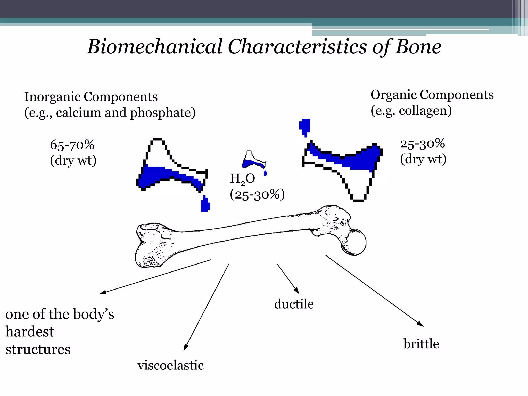
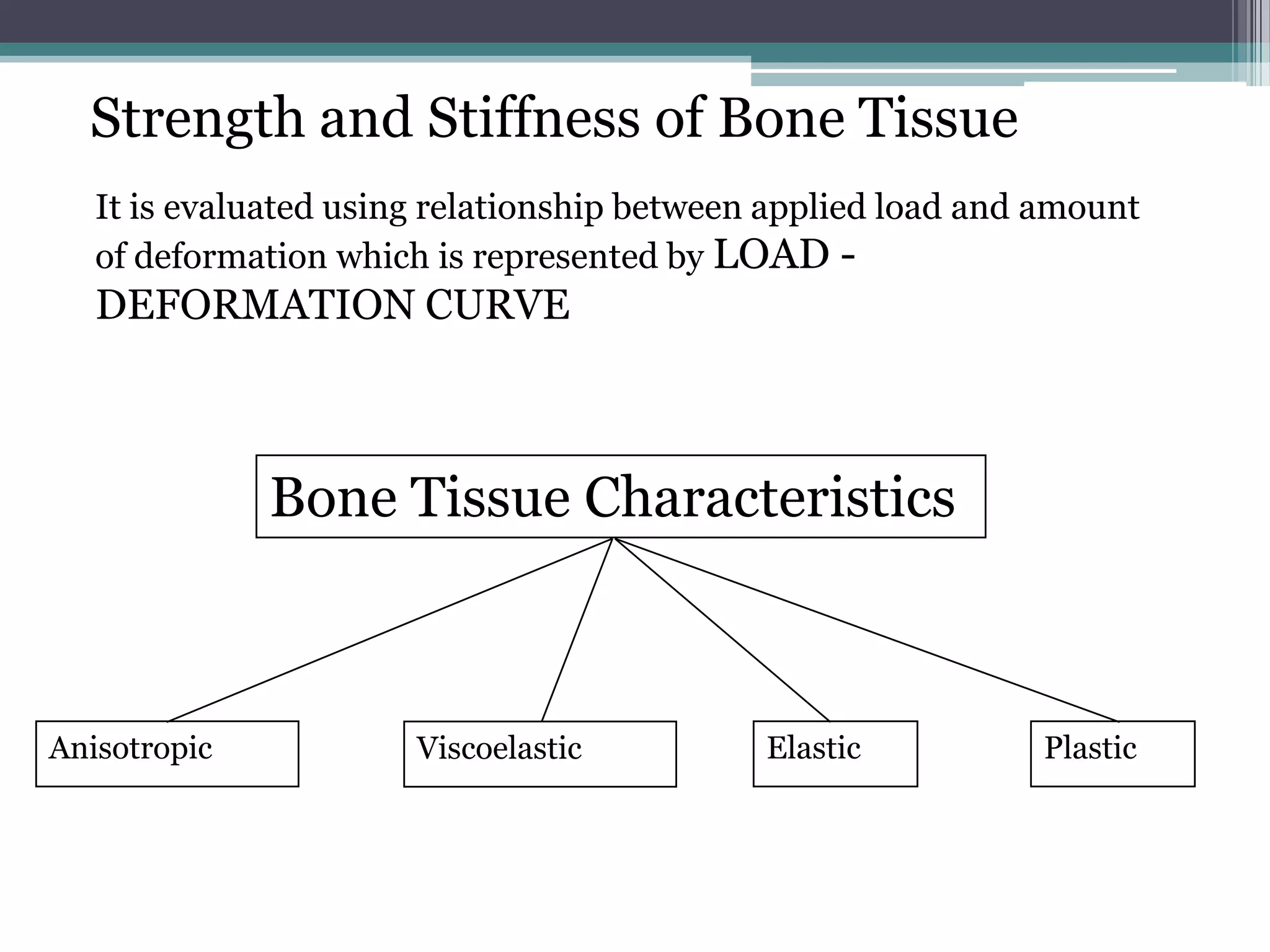
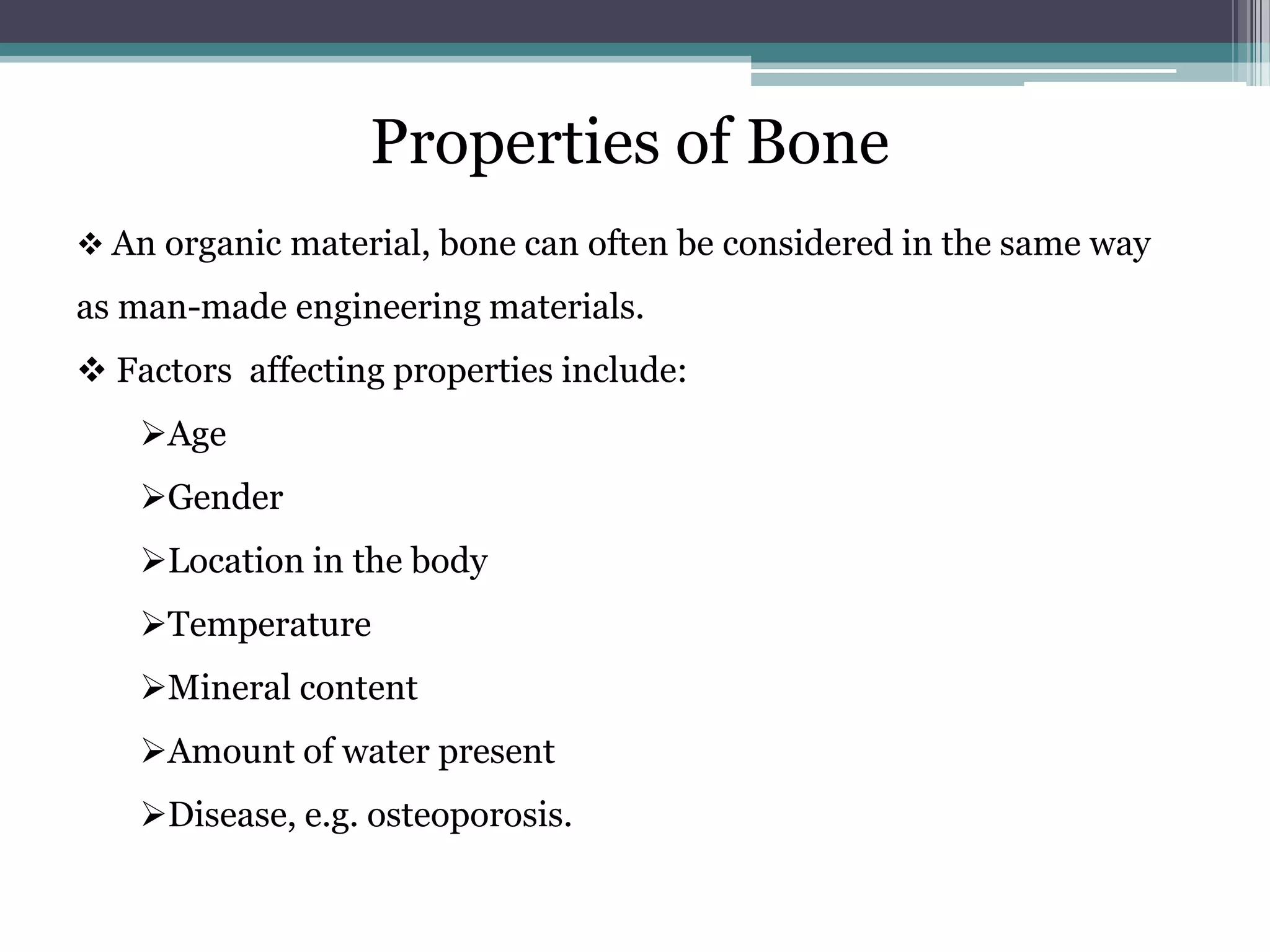
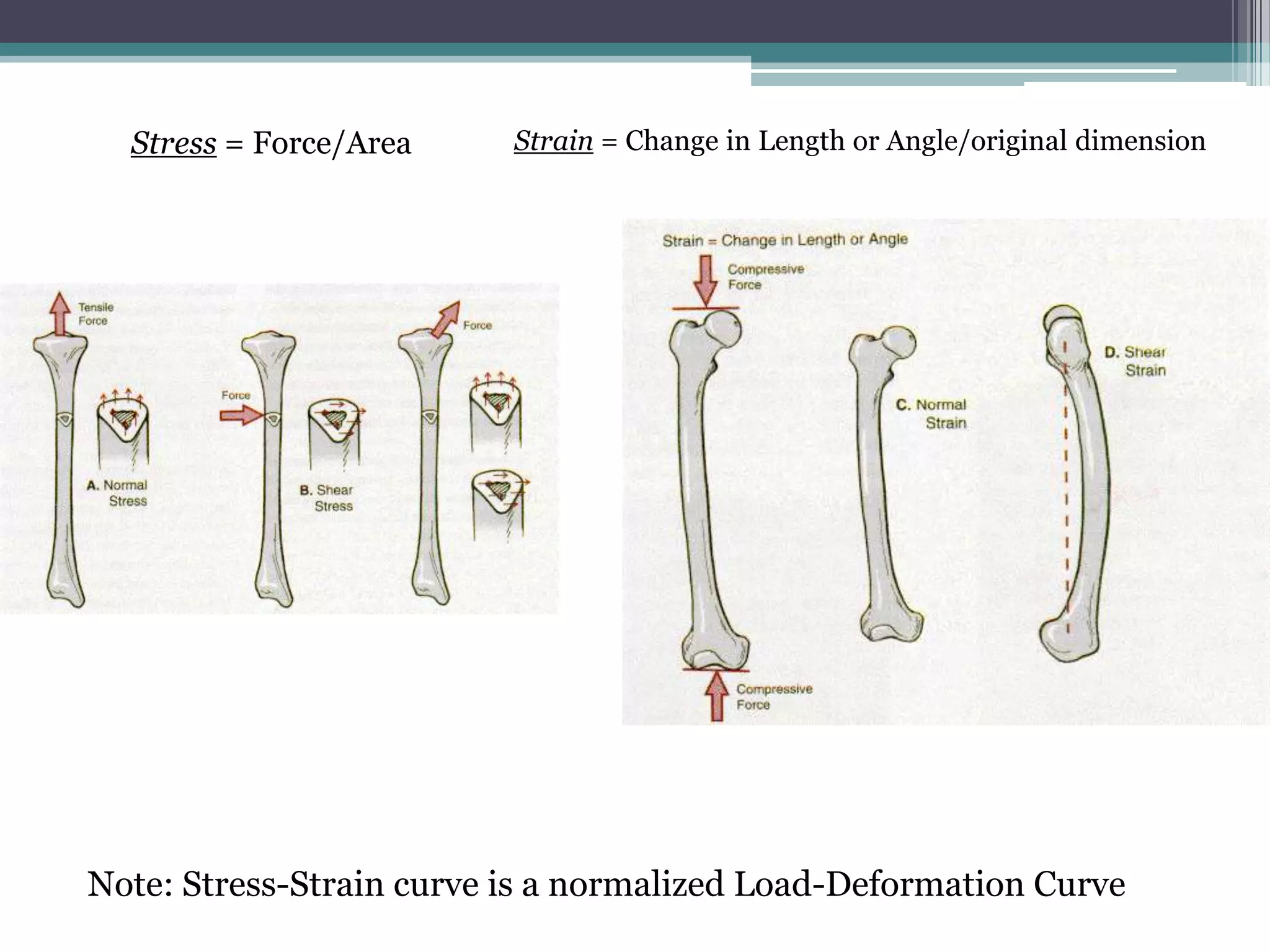
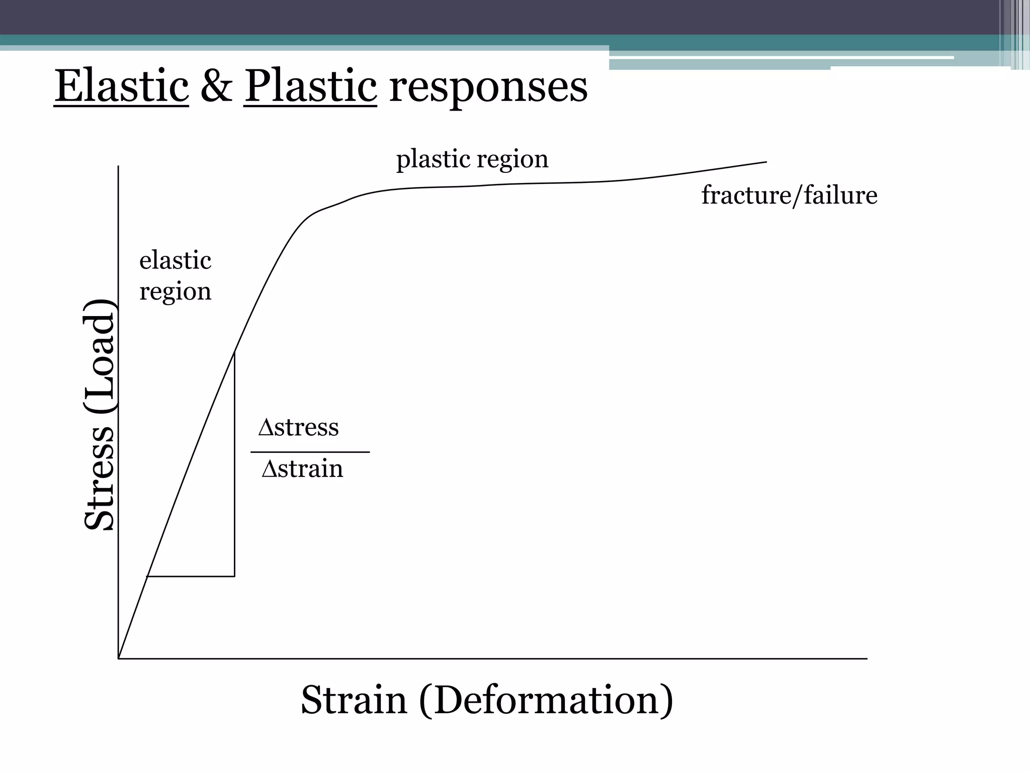
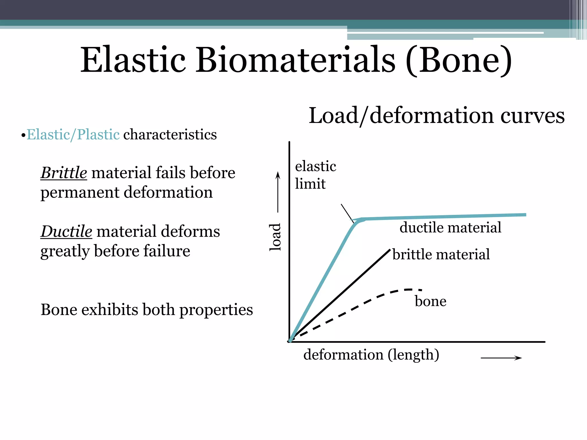
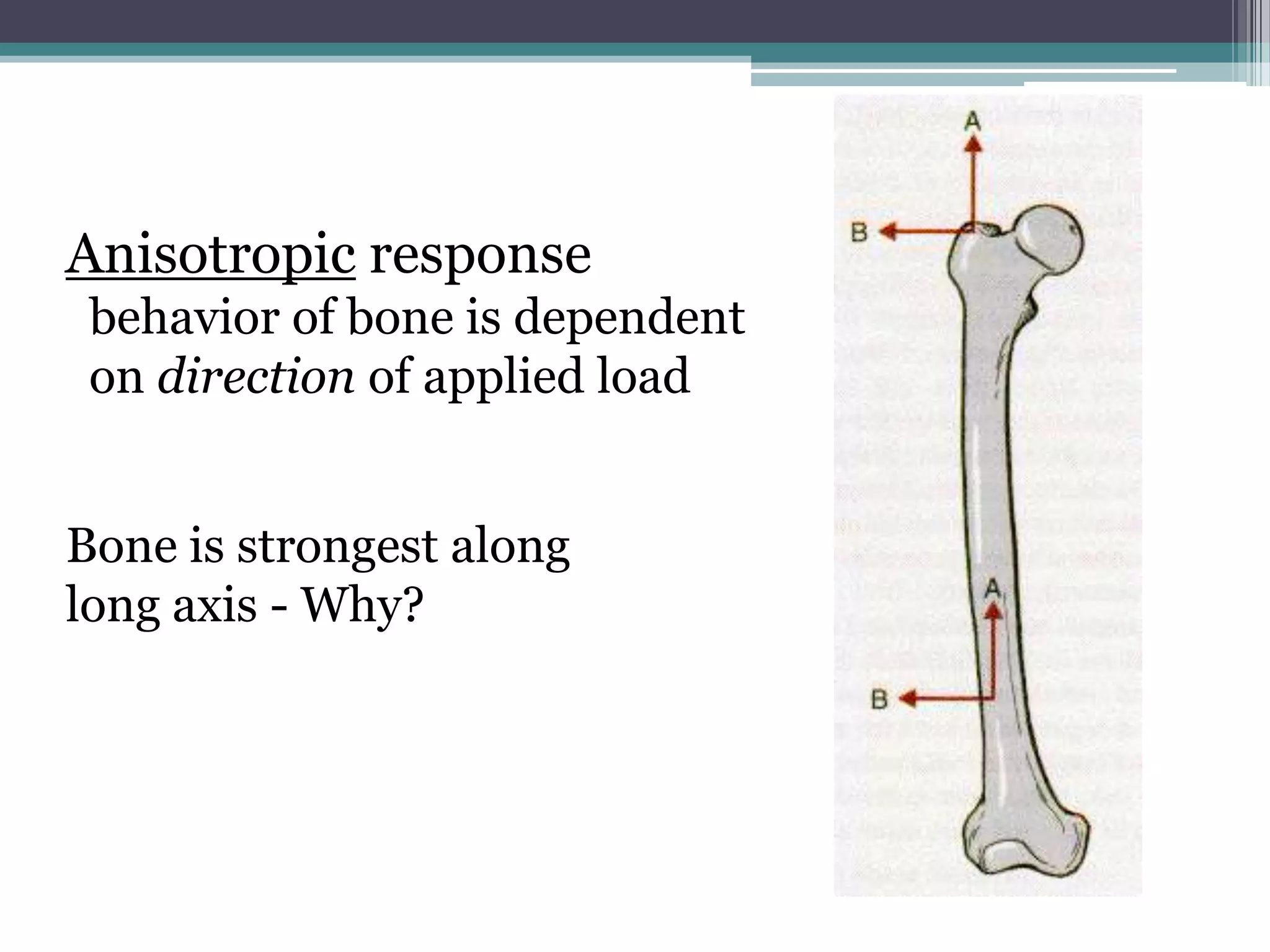
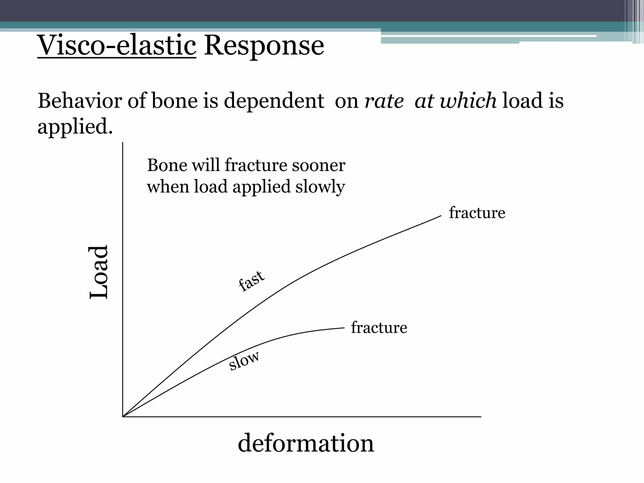
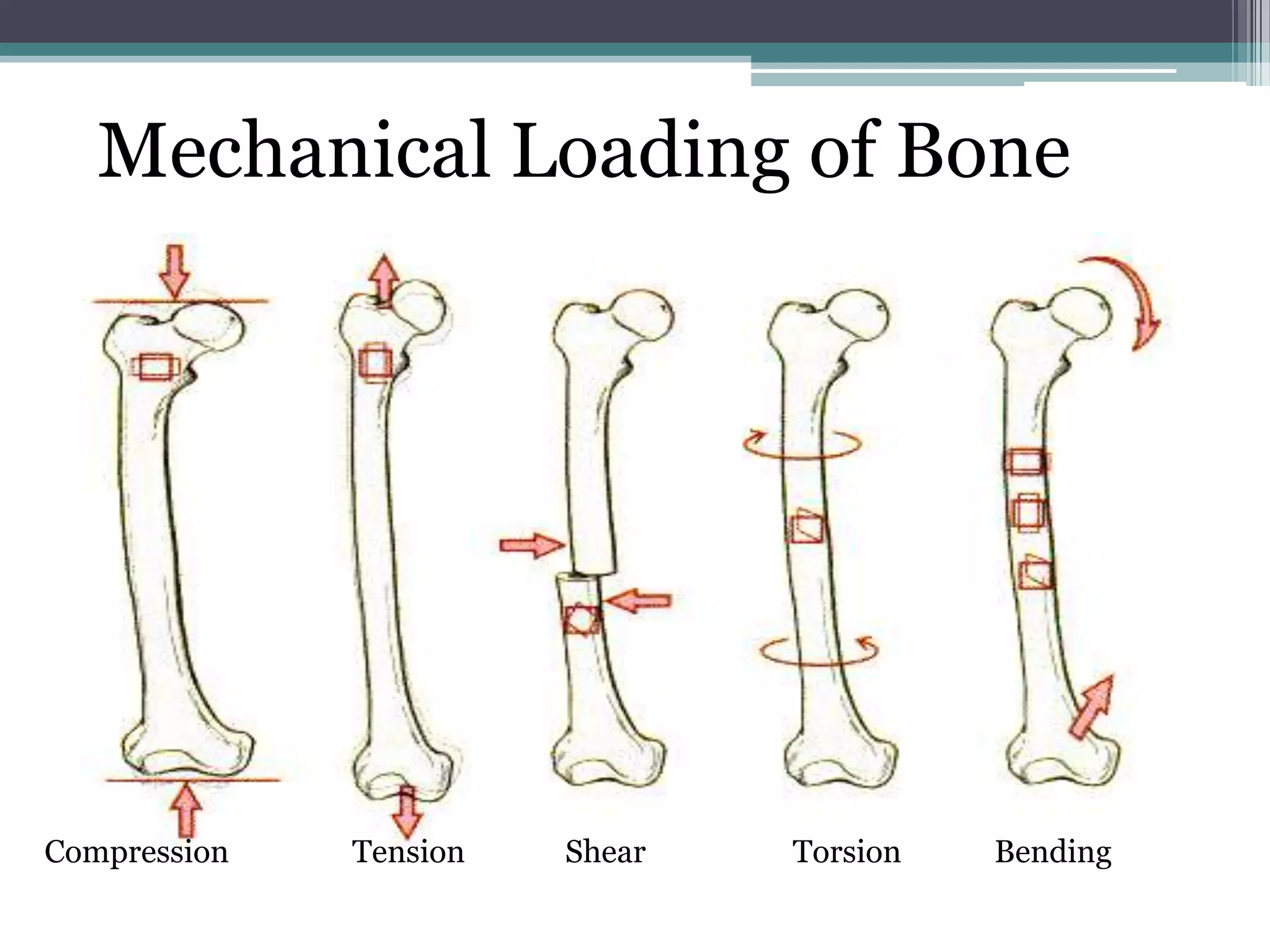
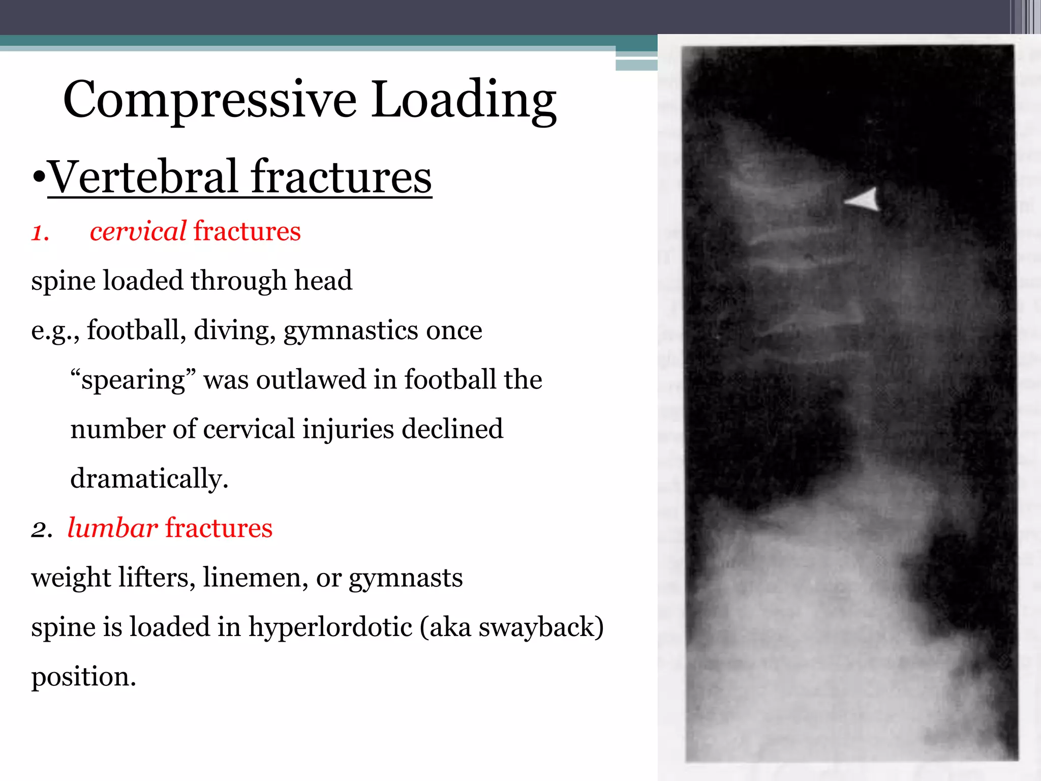
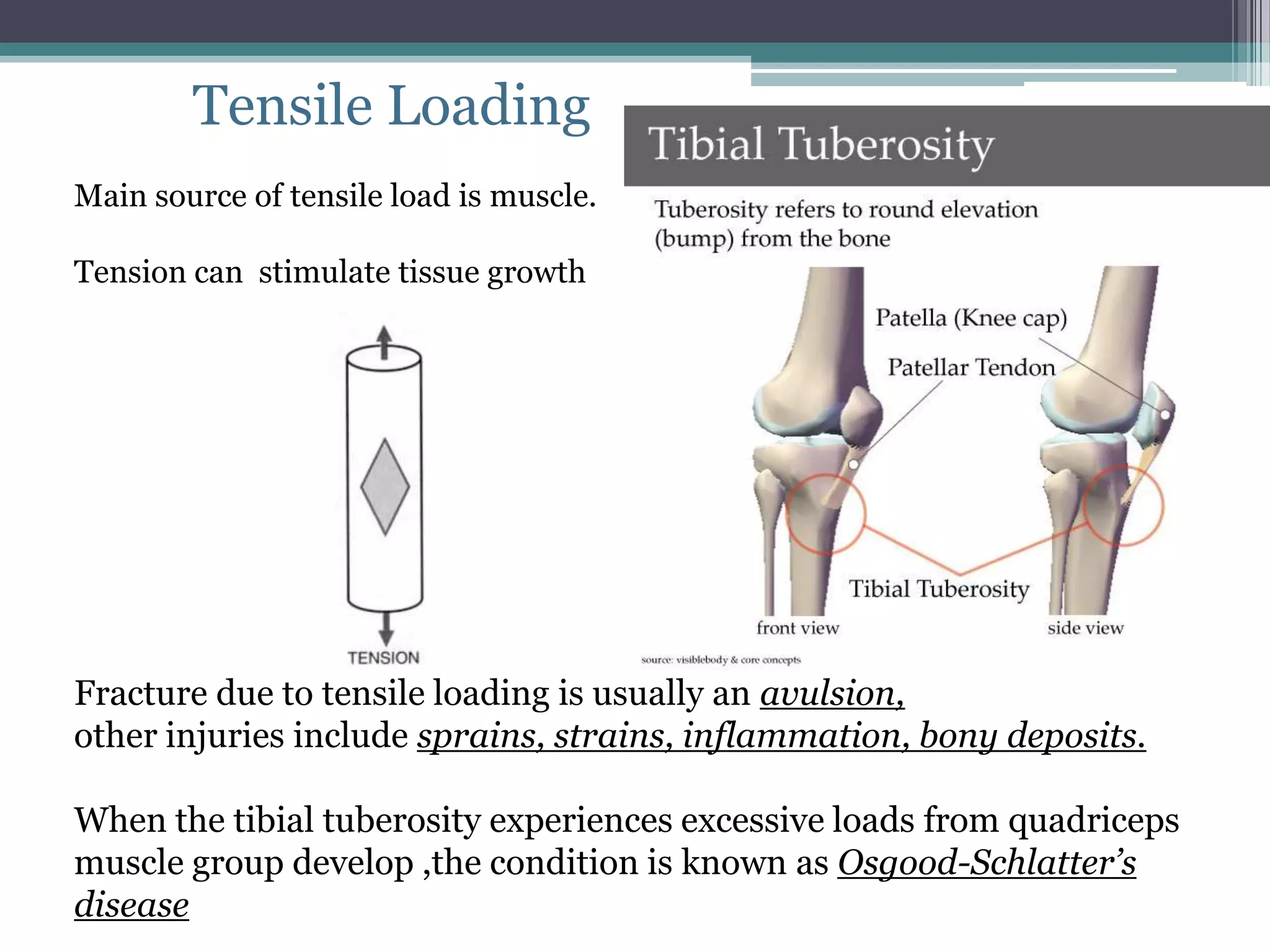
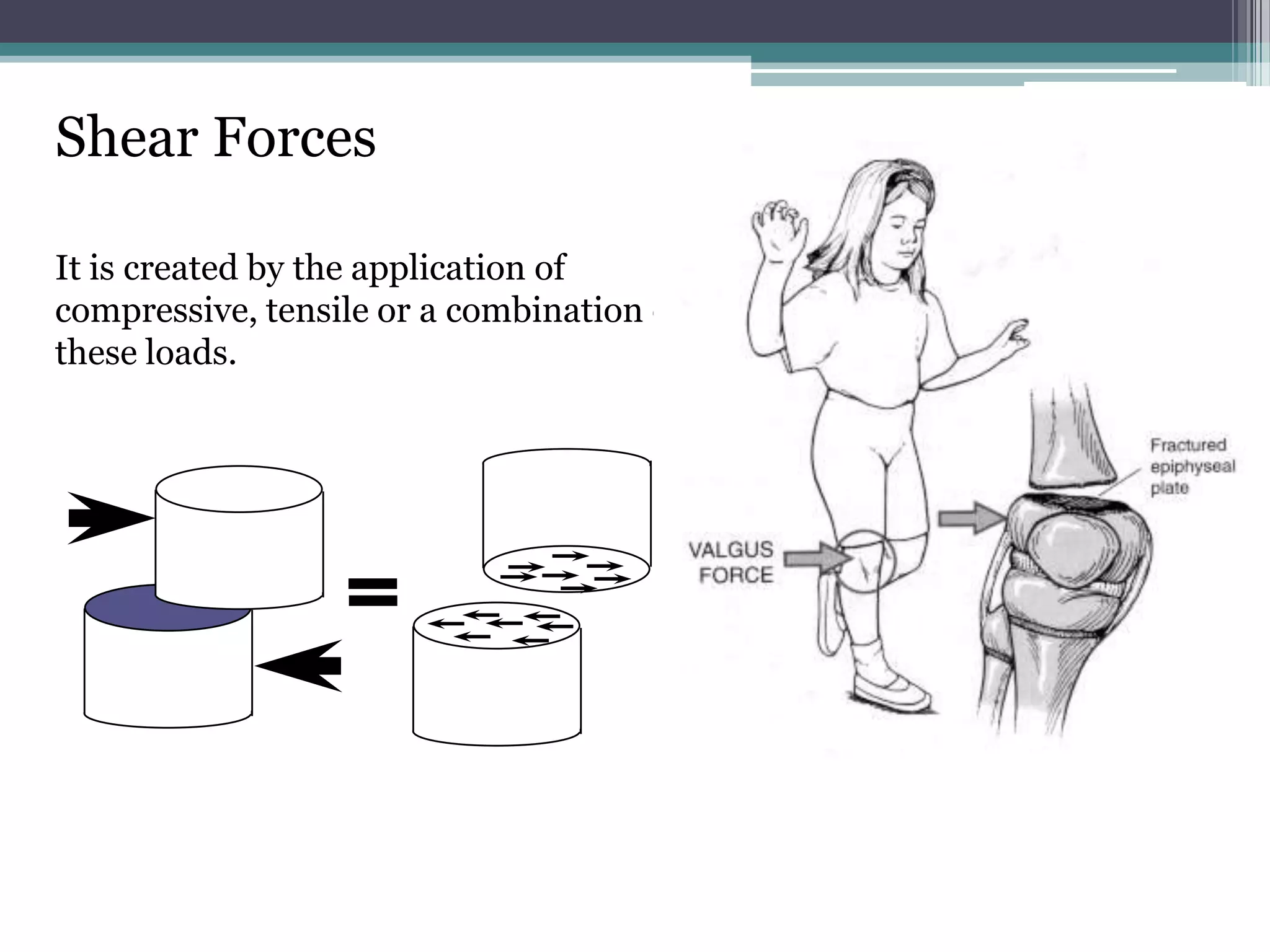
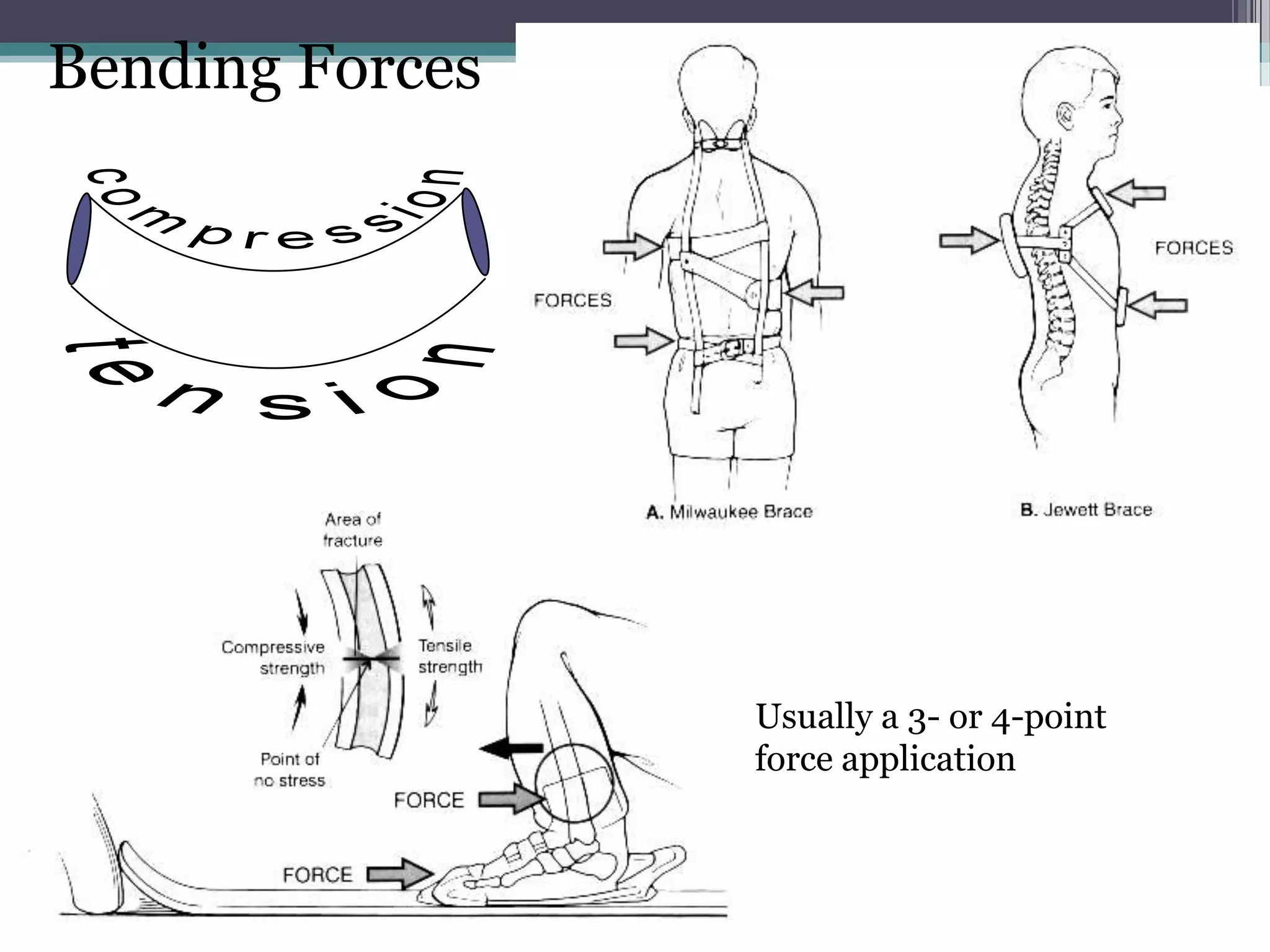
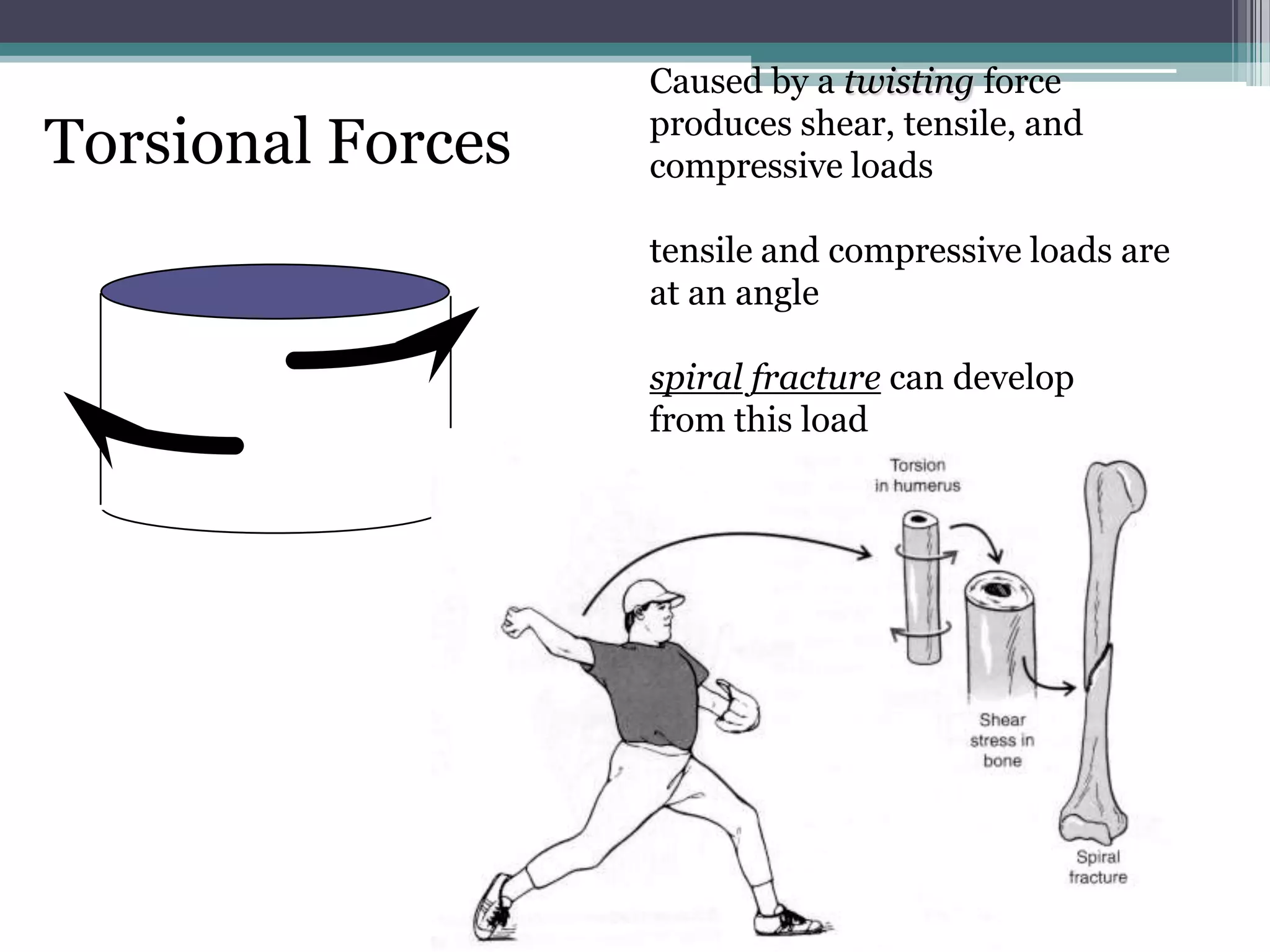
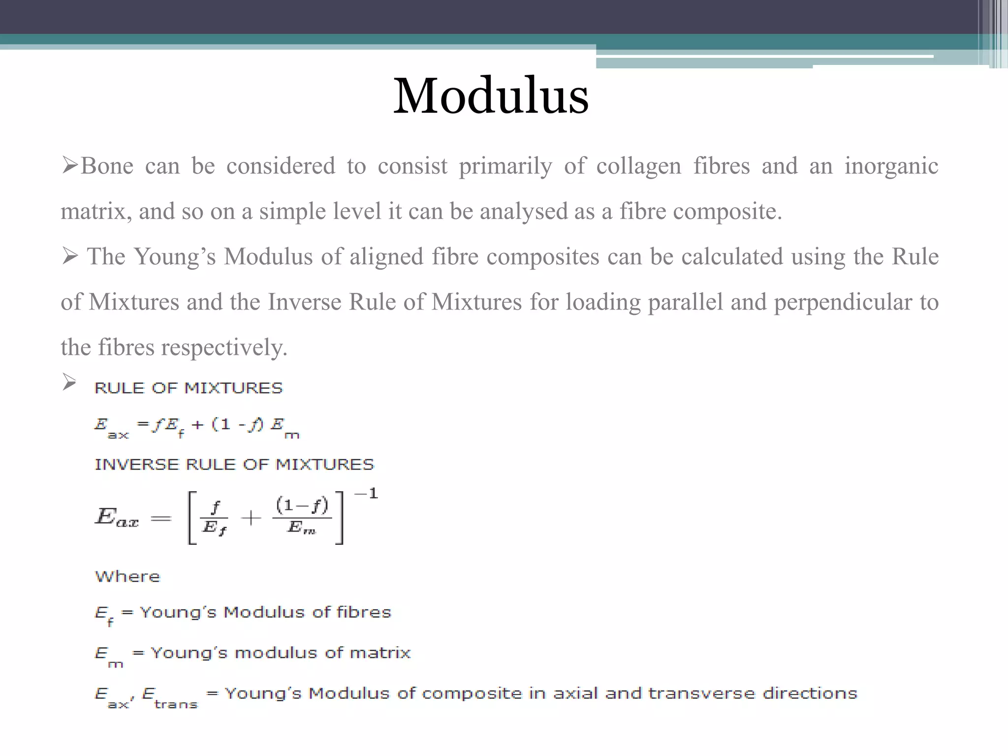


The document discusses the biomechanical properties and characteristics of human bone. It covers the following key points: 1. Bone tissue is a composite material made up of both organic and inorganic components that give it properties of being anisotropic, viscoelastic, elastic, and plastic. 2. The strength and stiffness of bone is evaluated using stress-strain curves which measure the relationship between applied load and the amount of deformation. 3. Bone exhibits different mechanical responses depending on the direction and rate of applied loads, such as tension, compression, shear, torsion, and bending. Factors like age, gender, and location in the body also influence its properties.


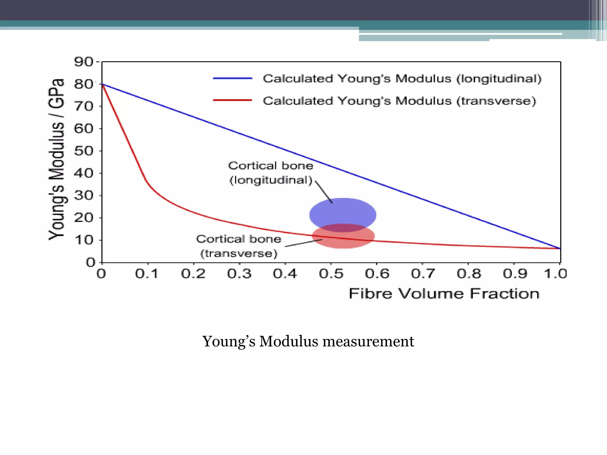
![Ppt Fits Tolerances[1]](https://cdn.slidesharecdn.com/ss_thumbnails/pptfitstolerances1-091107045206-phpapp01-thumbnail.jpg?width=640&height=640&fit=bounds)


