This document provides guidelines for the analysis, design, and construction of reinforced concrete foundations that support dynamic equipment. It discusses foundation and machine types, design loads, methods for calculating soil and pile impedances, vibration analysis and acceptance criteria, foundation design and materials, construction considerations, and repair options. Example problems are included to illustrate calculation procedures. Key areas covered in more detail than the previous edition include soil and pile impedance, vibration analysis methods, and determination of soil properties for dynamic analysis.


![REPORT ON FOUNDATIONS FOR DYNAMIC EQUIPMENT (ACI 351.3R-18) 3
ACI 351.2R was published prior to a major revision to ACI
3 1 8 and some of the section numbers that it references in
ACI 3 1 8 may have changed.
CHAPTER 2-NOTATION AND DEFINITIONS
2.1-Notation
A steady-state vibration amplitude, in. (mm)
Ahead,
Acrank=
Ap =
a, b =
B;
Emf=
BM =
B,.
b�, bz=
c
head and crank areas, in.2 (mm2)
cross-sectional area ofthe pile, in.2 (mm2)
plan dimension of a rectangular foundation, ft (m)
dimensionless frequency
cylinder bore diameter, in. (mm)
mass ratio for the i-th direction
machine footprint width, ft (m)
width ofmat foundation, ft (m)
ram weight, tons (kN)
constants 0.425 and 0.687, respectively
damping coefficient or total damping at center of
resistance
[C] damping matrix
CCR = critical damping coefficient
C
n,C
;2= dimensionless stiffness and damping parameters,
subscription i = u, v, jl, YJ
c viscous damping constant, lbf-s/ft (N-s/m)
c
; damping constant for the i-th direction
c
; (adj) = adjusted damping constant for the i-th direction
cu = equivalent viscous damping of pile j in the i-th
direction
CG= center ofgravity
CF center of force
Cg; pile group damping in the i-th direction
D damping ratio
D; damping ratio for the i-th direction
Drod= rod diameter, in. (mm)
d pile diameter, in (mm)
ds displacement ofthe slide, in. (mm)
dmf distance from machine shaft centerline to top of
foundation, ft (m)
E static Young's modulus of concrete, psi (MPa)
Ed dynamic Young's modulus of concrete, psi (MPa)
EP Young's modulus ofthe pile, psi (MPa)
em mass eccentricity, in. (mm)
F peak value of harmonic dynamic load (force or
moment)
F1 correction factor
Fblock= force acting outward on the block from which
concrete stresses should be calculated, lbf(N)
(FbottkHc = force to be restrained by friction at the crosshead
guide tie-down bolts, lbf(N)
(FbotJJrame = force to be restrained by friction at the frame
tie-down bolts, lbf (N)
FD = damper force, lbf(N)
FGMAx= maximum horizontal gas force on a throw or
cylinder, lbf (N)
F1M� maximum horizontal inertia force on a throw or
cylinder, lbf (N)
force in vibration isolator spring, lbf (N)
dynamic force amplitude (zero-to-peak), lbf (N)
lateral/longitudinal pseudo-dynamic design force,
lbf (N)
Fpv vertical pseudo-dynamic design force, lbf (N)
F,. maximum horizontal dynamic force, lbf (N)
Fred = force reduction factor to account for the fraction of
individual cylinder load carried by the compressor
frame (frame rigidity factor)
Frod = force acting on piston rod, lbf(N)
Fs = dynamic inertia force of slide, lbf (N)
FrHRovF horizontal force to be resisted by each throw's
anchor bolts, lbf (N)
F(t)= generic representation of time-varying load (force
or moment) horizontal
Funbatance= maximum value applied using parameters for a
horizontal compressor cylinder, lbf (N)
fc' specified concrete compressive strength, psi (MPa)
f
n,Ji2= dimensionless pile stiffness and damping functions
for the i-th direction
K
[KJ
K'
Ku*=
operating speed, rpm
dynamic shear modulus of the soil, psi (MPa)
torsional stiffness ofthe pile, lbf-ft2 (N-m2)
dynamic shear modulus of the embedment (side)
material, psi (MPa)
depth of soil layer, ft (m)
gross area moment of inertia, in.2 (mm2)
moment of inertia of the pile cross section in.4
(mm4)
-1-1
directional indicator or modal indicator, as a
subscript
stiffness or total stiffness at center ofresistance, lbf/
ft (N/m) or lbf-ft/rad (N-m/rad)
stiffness matrix
total stiffness at center of gravity, lb£'ft (N/m) or
lbf-ft/rad (N-m/rad)
impedance in the i-th direction due to a displace
ment in thej-th direction
actual negative stiffness, lbf/ft (N/m) or lbf-ft/rad
(N-m/rad)
arbitrary chosen positive stiffness value (typically
set equal to the static stiffness), lbf/ft (N/m) or
lbf-ft/rad (N-m/rad)
effective bearing stiffness, lbf/in. (N/mm)
static soil stiffness, lbf/in3 (N/m3)
pile group coupling impedance
pile group horizontal impedance
pile group vertical impedance
pile group rocking impedance
individual pile stiffness at center of resistance, lbf/
ft (N/m) or lbf-ft/rad (N-m/rad)
impedance in the i-th direction due to embedment
pile group stiffness in the i-th direction, lbf/ft (N/m)
or lbf-ft/rad (N-m/rad)
static stiffness for the i-th direction, lbf/ft (N/m) or
lbf-ft/rad (N-m/rad)
American Concrete Institute
Provided by IHS Markit under license with ACI
No reproduction or networking permitted without license from IHS
Licensee=Chongqing Institute of quality and Standardizationb 5990390
American Concrete Institute- Copytri!!lflt�.@11Wlfe¥i11�3!l www.concrete.org](https://image.slidesharecdn.com/351-220912142741-528c03ea/85/351-3r-18-report-on-foundations-for-dynamic-equipment-pdf-5-320.jpg)
![4 REPORT ON FOUNDATIONS FOR DYNAMIC EQUIPMENT (ACI 351.3R-18)
k
;' frequency-dependent impedance in the i-th
direction
k
; (adj) = adjusted static stiffness for the i-th direction, lbf/ft
(N/m) or lbf-ft/rad (N-m/rad)
k
;' (adj)= adjusted frequency-dependent impedance in the
i-th direction
k
u stiffness ofpile) in the i-th direction, lbf/ft (N/m) or
lbf-ft/rad (N-m/rad)
ks
kst
ku
*
kv*
k./
�·
k(w)=
L
lp
M
[MJ =
M =
0
MR =
M,.
Mres=
Mt;
m
m,.
mrec
static stiffness of an individual pile j in the i-th
direction, lbf/ft (N/m) or lbf-ft/rad (N-m/rad)
soil modulus of subgrade reaction, lbf/in3 (N/m3)
static stiffness constant
horizontal impedance of supporting medium
vertical impedance of supporting medium
rocking impedance ofsupporting medium
torsional impedance of supporting medium
frequency (w)-dependent dynamic impedance
length ofconnecting rod, in. (mm)
greater plan dimension of the mat foundation, ft
(m)
machine footprint length, ft (m)
lateral distance from center of resistance to indi
vidual piles, ft (m)
depth of embedment, ft (m)
pile length, ft (m)
mass, Ibm (kg)
mass matrix
hammer mass, including any auxiliary foundation,
Ibm (kg)
overturning moment on foundation, lbf-ft (N-m)
mass ratio of concrete foundation to machine
ram mass, including dies and ancillary parts, Ibm
(kg)
foundation overturning resistance, lbf-ft (N-m)
added mass, Ibm (kg)
mass ofthe machine-foundation system; Ibm (kg)
slide mass including the effects of any balance
mechanism, Ibm (kg)
rotating mass, Ibm (kg)
reciprocating mass in a reciprocating machine, Ibm
(kg)
m,v1 rotating mass in a reciprocating machine, Ibm (kg)
m5 = added mass (inertial), Ibm (kg)
N number ofpiles
(NboltkHc = number of bolts holding down one cross-
head guide
(Nbo!t)frame = number of bolts holding down the frame, per
cylinder
NT = normal torque, lbf-ft (N-m)
PALL= allowable bearing pressure, ksf (kPa)
Phead,
Pcrank= instantaneous head and crank pressures, psi (MPa)
Pmax= maximum bearing pressure, ksf(kPa)
Ps power being transmitted by the shaft at the connec
tion, horsepower (kilowatts)
R circular foundation radius, equivalent translation
radius ofrectangular foundation, ft (m)
R; equivalent radius ofrectangular foundation, ft (m)
R'¥a' R>¥b = equivalent rocking radius of foundation about a-
and b-axis, respectively, ft (m)
R� equivalent torsional radius of foundation, ft (m)
r length ofcrank, in. (mm)
r; radius of the crank mechanism of the i-th cylinder,
in. (mm)
r0 pile radius or equivalent radius, in. (mm)
S press stroke, in. (mm)
Sa11 allowable foundation settlement, in. (mm)
s1 service factor, used to account for increasing unbal-
ance during the design service life ofthe machine
sil , si2 = dimensionless stiffness and damping parameters
for side layer, subscription i = u, v, "'' 11
Smax = maximum foundation settlement, in. (mm)
SVR = seismic shear force due to the rigid foundation and
other rigid components, lbf (N)
SVs = seismic shear force due to the superstructure,
machine and other flexible components, lbf (N)
SVseismic=total seismic shear force machine-foundation
system, lbf (N)
s pile center-to-center spacing, ft (m)
[T] transfer matrix
TM mat foundation thickness, ft (m)
T,11;11 = minimum required anchor bolt tension, lbf (N)
u
Vmax=
Vpeak=
VRMs=
vs
y
y
'
(ji)=
y
"
(ji)=
Yc
Ye
time, s
displacement amplitude, in. (mm)
peak displacement amplitude, in. (mm)
compressive velocity ofa pile, ft/s (m/s)
transmissibility factor
Lysmer's analog wave velocity, ft/second (m/s)
maximum allowable bearing vibration, in. (mm)
peak velocity, in./s (mm/s)
root mean square velocity, in./s (mm/s)
shear wave velocity ofthe soil, ft/s (m/s)
post-impact hammer velocity, in./s (mm/s)
reference velocity = 18.4 ft/s (5.6 m/s) from a free
fall of 5.25 ft ( 1 .6 m)
ram impact velocity, ft/s (m/s)
equipment weight at anchorage location, lbf (N)
weight ofthe foundation, tons (kN)
machine weight, tons (kN)
rotating weight, lbf (N)
generic representation of displacement (transla
tional or rotational), in. (mm) or rad
generic representation of velocity (translational or
rotational), in./s (mm/s) or rad/s
generic representation ofacceleration (translational
or rotational), in./s2 (mm/s2) or rad/s2
crank pin displacement in local y-axis, or distance
from the center of gravity to the base support, in.
(mm)
distance from the center of gravity to the level of
embedment resistance, ft (m)
crank pin displacement in local z-axis, in. (mm)
piston displacement, in. (mm)
angle between battered piles and vertical piles, rad
ram rebound velocity to impact velocity ratio
American Co ete Ins Licensee=Chongqing Institute of quality and Standardizationb 5990390
Provided by I ftQJn r license with ACI American Concrete Institute- Copyright� @>fMate'l'laf6L21W�oncrete.org
No reproduction��or mg permitted without license from IHS](https://image.slidesharecdn.com/351-220912142741-528c03ea/85/351-3r-18-report-on-foundations-for-dynamic-equipment-pdf-6-320.jpg)
![1 0 REPORT ON FOUNDATIONS F O R DYNAMIC EQUIPMENT (ACI 351.3R-18)
GAS
FLOW
�
+Z
MACIDNE
ROTATION
+Y
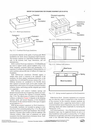
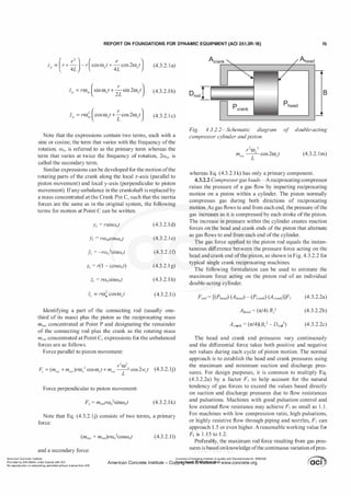
Fig. 4.2.3.Ja-Equivalentf
orcesf
or torque loads.
Shaft rotation
I. Spacing t
•�
�
,
Force = torque/spacing
Fig. 4.2.3. 1b-Equivalent f
orces f
or torque loads-torque
resisted by longitudinal equipment soleplates.
The torque load is generally resolved into a vertical force
couple by dividing itbythe center-to-center distance between
longitudinal soleplates or anchor points (Fig. 4.2.3. 1b).
When the machine is supported by transverse soleplates
only, the torque is applied along the width of the soleplate
assuming a straight line variation of force (Fig. 4.2.3.lc).
The torque on a generator stator is applied in the same
direction as the rotation of the rotor and can be high due to
startup or an electrical short circuit.
4.2.3.2 Condenser vacuum loads-For steam turbine
generator machines, usually a condenser is connected to
the low-pressure (LP) turbine and may share one common
foundation with the steam turbine-generator. The condenser
generates vacuum loads on the steam turbine (LP turbine)
when an expansion joint is provided between the condenser
duct and the LP turbine exhaust neck. Condenser vacuum
loads are normally based on zero absolute pressure. The
vacuum loads can act vertically on the tabletop of the foun
dation if the condenser is located directly below the LP
turbine, and it can also act laterally to the foundation if the
condenser is not located directly below the LP turbine. The
magnitude ofthe vacuum load can be estimated as the stan
dard atmospheric pressure (14.7 psi [101.4 kPa]) times the
Shaft rotation
Width
Force/length = 6 x torque/width2
Fig. 4.2.3. 1c-Equivalent f
orces for torque loads-torque
resisted by transverse equipment soleplates.
neck duct opening area ofthe LP turbine. The vacuum loads
are normally supplied by the machine manufacturer.
4.2.3.3 Axial thrust loads-Axial loads result from gas
flow momentum changes through gas turbines, or from the
pressure differences between the gas inlet and exhaust. These
loads generally are treated as a static load whose magnitude
varies depending on the normal operation level exhaust of
back pressure or shut-down level of exhaust back pressure.
The axial thrust loads are normally supplied by the machine
manufacturer.
4.2.3.4 Piping loads-Piping forces can be calculated
based on the pipe stress analysis, taking into account the
pipe weight (including insulation weight), fluid weight, fluid
dynamics, thermal expansion/contractions, valve opera
tions, and environmental load conditions (seismic, wind, and
ice). These forces are transferred to the foundation by pipe
supports, attachments, or anchors attached to the foundation
along the piping system.
The piping load results from steam pipes and circulating
water pipes attached to the turbine sections. The resultant
piping loads acting on various points of support and guid
ance for the turbine casing reach the foundation as forces.
During a valve trip, the turbine foundation can be subjected
to significant piping valve trip loads. The piping loads
usually are determined by the mechanical pipe engineers.
4.2.3.5 Thermal loads-Changing temperatures of
machines and their foundations cause expansions, contrac
tions, and distortions, causing the various parts to try to
slide on the support surfaces. Thermal loads or self-straining
loads may be divided into one ofthree loads types:
a) Thermal friction loads
b) Thermal expansion/contraction loads
c) Temperature change and temperature gradient change
on the foundation member cross section
Licensee=Chongqing Institute of quality and Standardizationb 5990390
American Concrete Institute- Copyright� @>fMate'l'laf6L21W�oncrete.org](https://image.slidesharecdn.com/351-220912142741-528c03ea/85/351-3r-18-report-on-foundations-for-dynamic-equipment-pdf-12-320.jpg)
![1 2 REPORT ON FOUNDATIONS F O R DYNAMIC EQUIPMENT (ACI 351.3R-18)
part does not coincide with the axis of rotation. In theory,
it is possible to precisely balance the rotating elements of
rotating machinery. In practice, this is never achieved; slight
mass eccentricities always remain. During operation, the
eccentric rotating mass produces centrifugal forces that are
proportional to the square of machine speed. Centrifugal
forces generally increase during the design service life of
the machine due to conditions such as machine wear, rotor
play, and dirt accumulation.
Arotating machine transmits dynamic force to the founda
tion predominantly through its bearings (with small, gener
ally unimportant exceptions such as seals and the air gap in a
motor). The forces acting at the bearings are a function ofthe
level and axial distribution of the unbalance, the geometry
of the rotor and its bearings, the speed of rotation, and the
dynamic characteristics of the rotor-bearing system. At or
near a critical speed, the force from rotating unbalance can
be substantially amplified, sometimes by a factor of five or
more due to resonance.
The engineer should request the machine manufacturer to
provide the following information:
a) Design levels of unbalance and basis-This informa
tion defines the unbalance level that is the basis for calcu
lating the subsequent transmitted forces.
b) Dynamic forces transmitted to the bearing pedestals
under the following conditions:
1 . Unbalance levels over operating speed range
2. At highest vibration when running at critical speeds
3. At a vibration level where the machine is just short of
tripping due to high vibration
4. Maximum level of upset condition the machine is
designed to survive (for example, loss ofone or more blades)
Items 1 and 2 document the predicted dynamic forces
resulting from levels of unbalance assumed in design for
normaloperation. Usingthese forces, it is possible topredictthe
normal dynamic vibration ofthe machine and its foundation.
Item 3 identifies a maximum level of transmitted force
under which the machine could operate continuously without
tripping; the foundation should have the strength to tolerate
such a dynamic force on a continuous basis.
Item 4 identifies the higher level of dynamic forces that
could occur under occasional upset conditions over a short
period of time. If the machine is designed to tolerate this
level of dynamic force for a short period of time, then the
foundation should also be designed to tolerate it for a similar
period.
If an independent dynamic analysis of the rotor-bearing
system is performed by the manufacturer, the end user, or a
third party, the results likely provide some or all the above
dynamic forces transmitted to the foundation.
By assuming that the dynamic force transmitted to the
bearings equals the rotating unbalanced force generated by
the rotor, information on unbalance can be used to estimate
or confirm the transmitted force.
4.3.1.1 Machine unbalance load provided by manuf
ac
turer-When the mass unbalance (eccentricity) is known
or stated by the manufacturer, the resulting dynamic force
amplitude is
(4.3. 1 . 1 )
where Fa should be distributed to the bearings considering
the rotor/shaft span between bearings as a simple beam and
the center of mass ofthe rotor location within the span.
4.3.1.2 Machine unbalance load (meeting industry
criteria)-Many rotating machines are balanced to an initial
balance quality either in accordance with the manufacturer's
procedures or as specified by the purchaser. ISO 1940-1
and ASA/ANSI S2. 19 define balance quality in terms of
a constant emW0• For example, the normal balance quality
Q for parts of process-plant machinery is 0.25 in./s (6.3
mm/s). Typical balance quality grade examples are shown
in Table 4.3.1.2. To meet these criteria, a rotor intended for
faster speeds should be better balanced than one operating
at a slower speed. Using this approach, Eq. (4.3 . 1 . 1) can be
rewritten as
(4.3.1 .2a)
where Q is in inch-pound and SI systems is ft/s and mm/s,
respectively.
API 617 and API 684 workwith maximum residual unbal
ance Umox criteria for petroleum processing applications. The
mass eccentricity is determined by dividing Umox by the rotor
weight. For axial and centrifugal compressors with maximum
continuous operating speeds greater than 25,000 rpm, API
617 establishes a maximum allowable mass eccentricity of
10 x 1 0--<i in. (254 nm). For compressors operating at slower
speeds, the maximum allowable mass eccentricity is
em = 0.25/fo (in.)
(4.3. 1 .2b)
em = 6.3/fo (mm)
where.fa is the less than or equal to 25,000 rpm.
This permitted initial mass eccentricity equates to ISO
1940-1 balance quality Grade 00.7, which is much smaller
than the 02.5 that would be applied to this type of equip
ment (Table 4.3.1 .2, turbo compressors). As such, the
dynamic force calculated from this API 617 consideration
will be quite small and a larger service factor might be used
to calculate a realistic design force.
API 617 also identifies a limitation on the peak-to-peak
vibration amplitude ((12,000!fo)05 mil [25.4(12,000!fo)0 5
J.lm]) during mechanical testing of the compressor with the
equipment operating at its maximum continuous speed. Some
design firms use this criterion as a mechanical test vibration
limit for the mass eccentricity em, using Eq. (4.3.1 .2a), and a
service factor S1of2.0 to calculate the zero to peak dynamic
force amplitude as
Licensee=Chongqing Institute of qualityand Standardizationb 5990390
American Concrete Institute- Copyright� @>fMate'l'laf6L21W�oncrete.org](https://image.slidesharecdn.com/351-220912142741-528c03ea/85/351-3r-18-report-on-foundations-for-dynamic-equipment-pdf-14-320.jpg)
![REPORT ON FOUNDATIONS FOR DYNAMIC EQUIPMENT (ACI 351.3R-18) 13
Table 4.3.1.2-Balance quality grades for selected groups of representative rigid rotors'
Balance quality Product of ero,
guide in./s (mm/s) Rotor types-general examples
G l 600 63 ( 1600) Crankshaft/drives of rigidly mounted, large, two-cycle engines
G630 25 (630) Crankshaft/drives of rigidly mounted, large, four-cycle engines
G250 10 (250) Crankshaft/drives of rigidly mounted, fast, four-cylinder diesel engines
GIOO 4 (100) Crankshaft/drives of fast diesel engines with six or more cylinders
G40 1.6 (40) Crankshaft/drives of elastically mounted, fast four-cycle engines (gasoline or diesel) with six or more cylinders
G l 6 0.6 ( 1 6)
Parts of crushing machines; drive shafts (propeller shafts, cardan shafts) with special requirements; crankshaft/
drives ofengines with six or more cylinders under special requirements
Parts ofprocess plant machines; centrifuge drums, paper machinery rolls, print rolls; fans; flywheels; pump
G6.3 0.25 (6.3) impellers; machine tool and general machinery parts; medium and large electric annatures (ofelectric motors
having at least 3-1/4 in. [80 mm] shaft height) without special requirement
G2.5 0. 1 (2.5)
Gas and steam turbines, including marine main turbines; rigid turbo-generator rotors; turbo-compressors;
machine tool drives; medium and large electric armatures with special requirements; turbine driven pumps
G l 0.04 ( 1 ) Grinding machine drives
G0.4 0.015 (0.4) Spindles, discs, and armatures ofprecision grinders
"Excerpted from ASA/ANSI S2. 19.
W f l.s
F = r o
0 322,000
(4.3.1 .2c)
Units of Fa and w;. are lbf and N in inch-pound and SI
systems, respectively.
4.3.1.3 Machine unbalance load (determined f
rom a
f
ormula)-Rotating machine manufacturers often do not
report the unbalance that remains after balancing. Conse
quently, formulas are frequently used to ensure that foun
dations are designed for some minimum unbalance, which
generally includes some allowance for unbalance increases
over time. One general-purpose method assumes that
balancing improves with machine speed and that there is a
linear relationship between the unbalanced forces and the
machine speed. The zero-to-peak centrifugal force ampli
tude from Eq. (4.3. 1 .2a) and (4.3.1 .2b) and a service factor
ofS
1of2.5 from one such commonly used expression is
W,.J;,
6000
(4.3. 1 .3)
where units ofFa and w;. are lbfand N in inch-pound and SI
systems, respectively.
Equations (4.3. 1 . 1), (4.3. 1 .2a), (4.3. 1 .2c), and (4.3. 1 .3)
appear to be very different: the exponents on the speed
of rotation vary from 1 to 1 .5 to 2, constants vary widely,
and different variables appear. Some equations use mass,
others use weight. In reality, the equations are more similar
than they appear. Given the right understanding of Q as a
replacement for e111ffia, Eq. (4.3. 1 . 1), (4.3.1 .2a), and (4.3. 1 .3)
take on the same character. These equations then indicate
that the design force at operating speed varies linearly with
both the mass of the rotating body and the operating rota
tional speed. Once that state is identified, Eq. (4.3.1 .1) can
be adjusted to reflect the actual speed of rotation, and the
dynamic centrifugal force is seen to vary with the square of
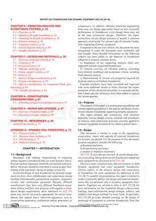
0.012
.£ 0.010
�
'(3 0.008
·;::
'E
§
0.006
UJ 0.004
�
t5 0.002
&
UJ 0
0
I;Eq. (4.3.1.2c)
I
� /
,..... Eq. (4.3. 1 .3)
� --�v
� ---..:: - - - - - - - - - -
2000 4000 6000 8000
Operating Speed, rpm
Fig. 4.3.1.3-Machine unbalanced loads-comparison of
e
ff
ective eccentricity.
the speed. Restating Eq. (4.3.1 .2c) and (4.3. 1 .3) in the form
of Eq. (4.3 . 1 .1) allows for the development of an effective
eccentricity implied within these equations with the compar
ison shown in Fig. 4.3. 1 .3. Equation (4.3. 1.3) produces the
same result as Eq. (4.3. 1 .2a) using Q = 0.25 in./s (6.3 mm/s)
and S
1= 2.5.
The centrifugal forces due to mass unbalance are consid
ered to act at the center of gravity of the rotating part and
vary harmonically at the speed of the machine in the two
orthogonal directions perpendicular to the shaft axis. The
forces in the two orthogonal directions are equal in magni
tude and 90 degrees out ofphase, and are transmitted to the
foundation through the bearings. Schenck (1990) provides
useful information about balance quality for various classes
ofmachinery.
4.3.1.4 Machine unbalance load (determined f
rom trip
vibration level and e
ff
ective bearing stUf
ness
)-Because a
rotor is often set to trip offat high vibration, it can be expected
to operate continuously at any vibration level up to the trip
limit. Given the effective bearing stiffness, it is possible to
calculate the maximum dynamic force amplitude as
American Concrete Institute
Provided by IHS Markit under license with ACI
No reproduction or networking permitted without license from IHS
Licensee=Chongqing Institute of quality and Standardizationb 5990390
American Concrete Institute- Copytri!!lflt�.@1!Wlfe¥i11�3!l www.concrete.org](https://image.slidesharecdn.com/351-220912142741-528c03ea/85/351-3r-18-report-on-foundations-for-dynamic-equipment-pdf-15-320.jpg)
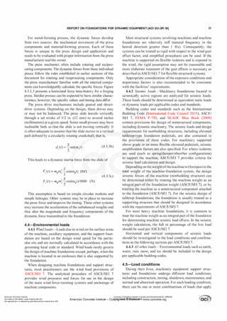
![1 4 REPORT ON FOUNDATIONS F O R DYNAMIC EQUIPMENT (ACI 351.3R-18)
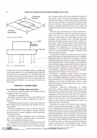
Crank Throw
(Length = r
"'
-�
>
]
0
6
Fig. 4.3.2. 1-Single crank mechanism.
(4.3. 1 .4)
To use this approach, the manufacturer should provide
effective bearing stiffness from the bearing geometry and
operating conditions (such as viscosity and speed) or provide
the corresponding forces for the foundation design.
4.3.1.5 Steam or gas turbine generator units-The deter
mination of the transmitted dynamic rotating unbalanced
forces from the bearings to the foundation, for large rotating
machines such as steam turbine generator units and combus
tion turbine generator units with complicated rotor configu
ration, shaft configurations, or both, can be completed by
a dynamic analysis of the rotor-bearing system (the rotor/
shaft power train dynamic analysis). This dynamic analysis
should be completed under varying conditions ofunbalance
and at varying speeds. This dynamic analysis is based on the
expected level ofrotor/shaft unbalance that corresponds to a
turbine generator rotor in operable condition but in need of
balancing. The analysis can be completed by using an appro
priate combination of computer programs for calculating
bearing dynamic characteristics and the response of the
rotor in the bearings due to the unbalance and the operating
speeds. Such an analysis would usually be performed by the
machine manufacturer. Results of such analyses, especially
values for transmitted bearing forces, represent the best
source ofinformation for use by the engineer responsible for
foundation design.
4.3.1.6 Loadsf
rom multiple rotating machines-Ifa foun
dation supports multiple rotating machines, the engineer
should calculate the unbalanced dynamic force based on
the mass, unbalance, and operating speed of each rotating
component. The response to each rotating mass is then
combined to determine the total response. Some practitio
ners, depending on the specific situation ofmachine size and
criticality, find it advantageous to combine the unbalanced
forces from each rotating component into a single resultant
unbalanced force. The method of combining two dynamic
forces is up to individual judgment and often involves some
approximations. In some cases, loads or responses can be
ylindcr
added absolutely. In other cases, the loads are treated as
out-of-phase so that twisting effects are increased. Often,
the operating speed of the equipment should be consid
ered. Even if operating speeds are nominally the same, the
engineer should recognize that during normal operation,
the speed of the machines will vary and beating effects can
develop. Beating effects develop as two machines operate at
close to the same speed. At one point in time, responses to
the two machines are additive and motions are maximized.
A short time later, the responses cancel each other and the
motions are minimized. The net effect is a continual cyclic
rising and falling ofmotion.
4.3.2 Reciprocating machine loads-Internal-combustion
engines, piston-type compressors and pumps, some metal
forming presses, steam engines, and other machinery are
characterized by the rotating motion of a master crankshaft
and the linear reciprocating motion of connected pistons or
sliders. The motion of these components causes cyclically
varying forces, often called reciprocating forces.
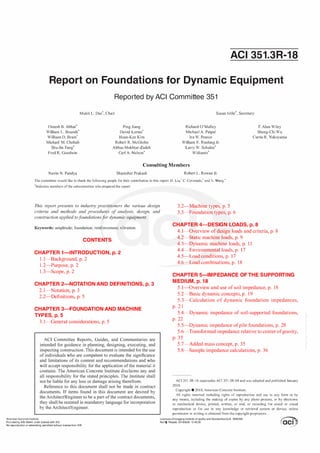
4.3.2.1 Primary and secondary reciprocating loads-The
simplest type of reciprocating machine uses a single crank
mechanism, as shown in Fig. 4.3.2. 1 . The idealization ofthis
mechanism consists of a piston that moves within a guiding
cylinder, a crank throw oflength r that rotates about a crank
shaft, and a connecting rod of length L. The connecting rod
is attached to the piston at Point P and to the crank at Point
C. The Wrist Pin P oscillates while the Crank Pin C follows
a circular path. This idealized single cylinder illustrates the
concept ofa machine producing both primary and secondary
reciprocating forces.
If the crank is assumed to rotate at a constant angular
velocity ffi0, the translational acceleration of the piston
along its axis may be evaluated. Ifzp is defined as the piston
displacement toward the crankshaft (local z-axis), an expres
sion can be written for zp at any time t. Further, the velocity
and acceleration can also be obtained by taking the first
and second derivatives of the displacement expression with
respect to time. The displacement, velocity, and acceleration
expressions for the motion ofthe piston are as follows.
American Co ete Ins Licensee=Chongqing Institute of quality and Standardizationb 5990390
Provided by I ftQJn r license with ACI American Concrete Institute- Copyright� @>fMate'l'laf6L21W�oncrete.org
No reproduction��or mg permitted without license from IHS](https://image.slidesharecdn.com/351-220912142741-528c03ea/85/351-3r-18-report-on-foundations-for-dynamic-equipment-pdf-16-320.jpg)
![1 6 REPORT ON FOUNDATIONS F O R DYNAMIC EQUIPMENT (ACI 351.3R-18)
sure in the cylinder (measured or predicted). In a repair situ
ation, measured cylinder pressure variation using a cylinder
analyzer provides the most accurate value ofgas forces. Even
without cylinder pressure analysis, extreme operating values
of suction and discharge pressure for each stage should be
recorded before the repair and used in Eq. (4.3.2.2a).
On new compressors, the engineer should ask the machine
manufacturer to provide values for maximum compressive
and tensile gas loads on each cylinder rod and to recom
mend a value ofF1 if these forces are based on suction and
discharge pressures.
Gas forces act on the crankshaft with an equal and oppo
site reaction to the force on the cylinder. Thus, crankshaft
and cylinder forces globally balance each other. Between the
crankshaft and the cylinder, however, the metal compressor
frame stretches or contracts in tension or compression under
the action ofthe gas forces. The forces due to frame deflec
tions are transmitted to the foundation through connections
with the compressor frame. When acting without slippage,
the frame and foundation become an integral structure and
together stretch or contract under the gas loads.
The magnitude ofgas force transferred into the foundation
depends on the relative flexibility of the compressor frame.
A very stiff frame transmits only a small fraction ofthe gas
force while a very flexible frame transmits most or all the
force. Similar comments apply to the transfer of individual
cylinder inertia forces.
Based on limited comparisons using finite element anal
ysis (Smalley 1 988), the following guidelines are suggested
for gas and inertia force loads transmitted to the foundation
by a typical compressor
Fblock = Frod/Fred (4.3.2.2d)
(Fbo!t)Jrame = [(Funba/ancdCNbo!t)]/Fred (4.3.2.2f)
The factor Fred is used to simplify a complex problem,
thus avoiding the application ofunrealistically high loads on
the anchor bolts and the foundation block. The mechanics
involved in transmitting loads are complex and cannot easily
be reduced to a simplerelationshipbetweena few parameters
beyond the given load equations. A detailed finite-element
analysis ofmetal compressor frame, chock mounts, concrete
block, and grout will account for the relative flexibility ofthe
frame and its foundation in determining individual anchor
bolt loads and implicitly provide a value forFred· Ifthe frame
is very stiff relative to the foundation, the value for Fred will
be higher, implyingmore ofthe transmitted loads are carried
by the frame and less by the anchor bolts and foundation
block. Based on experience, a value of 2 for this factor is
conservatively low; however, higher values have been seen
with frames designed to be especially stiff.
Simplifying this approach, Smalley and Harrell (1997)
suggest using a finite element analysis to calculate forces
transmitted to the anchor bolts. If a finite element analysis
is not possible, the engineer should obtain from the machine
manufacturer or calculate the maximum horizontal gas
force and maximum horizontal inertia force for any throw
or cylinder. The mounts, anchor bolts, and blocks are then
designed for
FTHRow = (greater ofFGMAX or F,MAX)/2 (4.3.2.2g)
4.3.2.3 Reciprocating inertia loads f
or multi-cylinder
machines-As a practical matter, most reciprocating
machines have more than one cylinder, and manufacturers
arrange the machine components in a manner that mini
mizes the net unbalanced forces. For example, rotating
parts such as the crankshaft can be balanced by adding or
removing correcting weights. Translating parts such as
pistons and those that exhibit both rotation and translation
such as connecting rods can be arranged in such a way as
to minimize the unbalanced forces and moments generated.
Seldom, if ever, is it possible to perfectly balance recipro
cating machines.
The forces generated by reciprocating mechanisms are
functions ofthe mass, stroke, piston arrangement, connecting
rod size, crankthrow orientation (phase angle), and the mass
and arrangement of counterweights on the crankshaft. For
this reason, calculating the reciprocating forces for multi
cylinder machines can be quite complex and are therefore
normally provided by the machine manufacturer. If the
machine is an integral engine compressor, it can include, in
one frame, cylinders oriented horizontally, vertically, or in
between, all with reciprocating inertias.
Some machine manufacturers place displacement trans
ducers and accelerometers on strategic points on the
machinery. They can then measure displacements and accel
erations at those points for several operational frequencies
to determine the magnitude of the unbalanced forces and
couples for multi-cylinder machines.
4.3.2.4 Estimating reciprocating inertiaf
orcesfrom multi
cylinder machines-In cases where the manufacturer's
data are unavailable or components are being replaced, the
engineer should use hand calculations to estimate the recip
rocating forces from a multi-cylinder machine. One such
procedure for a machine having n number of cylinders is
discussed by Mandke and Troxler (1992).
4.3.3 Impulsive machine loads-The impulsive load
generated by a forging hammer is caused by the impact of
the hammer ram onto the hammer anvil. This impact process
transfers the kinetic energy ofthe ram into kinetic energy of
the entire hammer assembly. The post-impact velocity ofthe
hammer is represented by
M
v" = -
' (1 + a,)v,
M"
(4.3.3a)
General experience indicates that a11 is approximately 60
percent for many forging hammer installations. From that
point, the hammer foundation performance can be assessed
as a rigid body oscillating as a single degree-of-freedom
SY,Stemlith an initial velocity ofv11•
American Co ete Ins Licensee=Chongqing Institute of quality and Standardizationb 5990390
Provided by I ftQJn r license with ACI American Concrete Institute- Copyright� @>fMate'l'laf6L21W�oncrete.org
No reproduction��or mg permitted without license from IHS](https://image.slidesharecdn.com/351-220912142741-528c03ea/85/351-3r-18-report-on-foundations-for-dynamic-equipment-pdf-18-320.jpg)
![1 8 REPORT ON FOUNDATIONS F O R DYNAMIC EQUIPMENT (ACI 351.3R-18)
Table 4.6-Load classifications for ultimate
strength design
Load
Design loads classification
Weight ofstructure, equipment, internals, insulation,
and platforms
Dead
Fluid loads during testing and operation
Anchor and guide loads
Platform and walkway loads
Materials to be temporarily stored during maintenance
Materials normally stored during operation such as tools
Live
and maintenance equipment
Vibrating equipment forces
Impact loads for hoist and equipment handling utilities
Seismic loads
Snow, ice, or rain loads Environmental
Wind loads
Notes. Thermal or self-strammg loads classJficatwns should be evaluated per reqUire
ments ofASCE/SEI 7.
Load due to lateral earth pressure, ground water pressure, orpressure ofthe bulk mate
rials classifications should be evaluated per guidelines ofASCE/SEl 7.
to the structure or foundation. The following load conditions
are generally considered in design:
a) Construction condition represents the design loads that
act on the structure/foundation during its construction.
b) Testing condition represents the design loads that act
on the structure/foundation while the equipment being
supported is undergoing testing, such as hydro test.
c) Normal operating condition represents the design
loading during periods ofnormal equipment operation.
d) Abnormal operating condition represents the design
loading during periods when unusual or extreme operating
loads act on the structure/foundation.
e) Maintenance condition (empty or shutdown) represents
the design loads that act on the structure when the supported
equipment is at its least weight due to removal of process
fluids, applicable internals, or both, as a result of mainte
nance or other out-of-service disruption.
4.6-Load combinations
Table 4.6 shows the general classification of loads for use
in determining the applicable load factors in strength design
(ACI 3 1 8; ASCE/SEI 7; ASCE/SEI 37). In considering soil
stresses or loading on piles, the normal approach is working
stress design without load factors and with overall factors of
safety identified as appropriate by geotechnical engineers.
The load combinations frequently used for the various load
conditions are as follows:
a. Construction
i. Dead loads + construction loads
ii. Dead loads + construction loads + reduced wind
loads + snow, ice, or rain loads
iii. Dead loads + construction loads + seismic loads +
snow, ice, or rain loads
b. Hydro testing
i. Dead loads + test loads
ii. Dead loads + test loads + live loads + snow, ice, or
rain loads
iii. Dead loads + test loads + reduced wind loads +
snow, ice, or rain loads
c. Normal operation
i. Dead loads + machine operation loads + live loads
(for multi bearings machine post-alignment deflection
check)
ii. Dead loads + machine operation loads + live loads +
wind loads + snow, ice, or rain loads
iii. Dead loads + machine operation loads + seismic
loads + snow, ice, or rain
d. Abnormal operation
i. Dead loads + upset (abnormal, emergency, cata
strophic) machine loads + live loads + reduced wind
loads
e. Maintenance loads
i. Dead loads + maintenance loads + live loads + snow,
ice, wind or rain loads
Environmental loads can be reduced per ASCE/SEI 37
when combined with maintenance or construction loads due
to the low probability ofthe loads occurring at the same time.
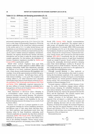
CHAPTER 5-IMPEDANCE OF THE SUPPORTING
MEDIUM
5.1-0verview and use of soil im pedance
The foundation dynamic response depends on the stiffness
and damping characteristics ofthe machine-foundation-soil
system. This section presents a general introduction to this
subject and a summary of approaches and formulas often
used to evaluate the stiffness and damping of both soil
supported and pile foundations. These stiffness and damping
relationships, collectively known as impedance, are used for
determining both free-vibration performance and motions of
the foundation system due to the dynamic loading associated
with the machine operation.
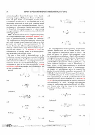
The simplest mathematical model used in dynamic anal
ysis of machine-foundation systems is a single-degree-of
freedom representation of a rigid mass vertically supported
on a single spring and damper combination (Fig. 5 . l(a)).
This model is applicable if the center of gravity of the
machine-foundation system is directly over the center ofsoil
resistance and the resultant of the dynamic forces (acting
through a center of force [CF]) is a vertical force passing
through the center ofgravity. The vertical impedance (kv*) of
the supporting medium is necessary for this model.
The next level of complexity is a two-degree-of-freedom
model commonly used when lateral dynamic forces act on
the system (Fig. 5 . l (b)). Because the lines of action of the
applied forces and the soil resistance do not coincide, the
rocking and translational motions ofthe system are coupled.
For this model, the engineerneeds to calculate the horizontal
translational impedance (ku*) and the rocking impedance
(k'l'*) of the supporting medium. These impedance values,
especially the rocking terms, are usually different about
different horizontal directions.
Application of the lateral dynamic forces can cause a
machine-foundation system to twist about a vertical axis.
To model this behavior, the engineer needs to determine
. . Licensee=Chongqing Institute of quality and Standardizationb 5990390
Amencan Concrete Institute- Copyright� @>fMate'l'laf6L21W�oncrete.org](https://image.slidesharecdn.com/351-220912142741-528c03ea/85/351-3r-18-report-on-foundations-for-dynamic-equipment-pdf-20-320.jpg)
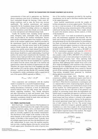
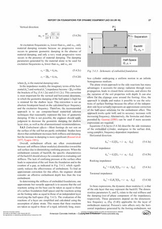
![REPORT ON FOUNDATIONS FOR DYNAMIC EQUIPMENT (ACI 351.3R-18) 25
(5.4. 1 . 11)
Vertical:
(5.4. 1 . 1 m)
Horizontal:
k, = 2(1 + v)G�, M (5.4. 1 . 1n)
Rocking (about an axis parallel to b):
(5.4. 1 . 1o)
The damping constants can be determined from the calcu
lated damping ratio, system mass, and stiffness as
(5.4. 1 . 1p)
or
(5.4. l . l q)
5.4.1.2 V
eletsos models-For the impedance functions of
infinitely rigid circular foundations resting on the surface of
a viscoelastic half-space, Veletsos and Verbic (1973) deter
mined the analytical expressions for the dynamic impedance
as a function offrequency, Poisson's ratio, and internal mate
rial damping. Neglecting the internal material damping, the
relationships for an infinitely rigid circular foundation are
Horizontal impedance:
(5.4. 1 .2a)
Rocking impedance:
Vertical impedance:
(5.4. 1 .2c)
3
�
""L:::::=::l'"
t---':-----1
•
..IC>
I
O ' z
!!!It
!::�
2
-
1---!-
1..--
...........IR
�
�.
IP'
z
1---
1.5
1.0
13,
0.5
0
0.2 0.4 0.6 1.0
LIB
2 4 6 8 10
Fig. 5.4.1. 1-Rectangularf
ooting coe
fficients (Richart etal.
1970).
Torsional impedance:
1 6G�
k� = -
3
-[A + ia0B]
A _ 1
b1 • (b2aj
and B =
b1b2 • (b2aj
where - -
(b )
2 2
1 + 2a0 1 + (b2aJ
(5.4. 1 .2d)
where j = 1 to 4 as appropriate and b1 and b2 = 0.425 and
'
:
0.687, respectively (Veletsos and Nair 1974). .
The leading terms of each of these impedance equa- ':
tions are the static stiffness of the foundation for vibration .
in that direction. For three cases (vertical, rocking, and
torsional motion), these terms are the same as presented in ;
the Richart-Whitman (Richart and Whitman 1967) lumped
parameter model. For the horizontal motion, there is a slight
difference due to assumptions about the foundation rigidity.
The practicality ofthe difference is small, especially toward
the higher range of Poisson's ratio values. These equations
may also be expressed as
Horizontal impedance:
(5.4. 1 .2e)
Rocking impedance:
(5.4. 1 .2f)
Vertical impedance:
(5.4. 1 .2g)
Torsional impedance:
(5.4. 1 .2h)
Constant approximations of Cil and C;2 are given in Table
5 .4. 1 .2 for twobroad classes ofsoils (cohesive and granular)
and for dimensionless frequency values a0 less than 2.0. The
American Concrete Institute
Provided by IHS Markit under license with ACI
No reproduction or networking permitted without license from IHS
Licensee=Chongqing Institute of quality and Standardizationb 5990390
American Concrete Institute- Copytri!!lflt�.@11Wlfe¥i1!l3!l www.concrete.org](https://image.slidesharecdn.com/351-220912142741-528c03ea/85/351-3r-18-report-on-foundations-for-dynamic-equipment-pdf-27-320.jpg)
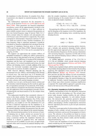
![30 REPORT ON FOUNDATIONS FOR DYNAMIC EQUIPMENT (ACI 351.3R-18)
Table 5.5.1-Stiffness and dam ping parameters for Eq (5 5 1a) to (5 5 1 k) for I /r > 25 (Novak 1974)
p 0
Stiffness parameters Damping parameters
v p/pp V,lvc ./7,1 .f9., /u,t /7,2 ./9,z /n,2
0.01 0.202 -0.0194 0.0036 0.139 -0.0280 0.0084
0.02 0.285 -0.0388 0.0100 0.200 -0.0566 0.0238
0.4 0.7 (Concrete) 0.03 0.349 -0.0582 0.01 85 0.243 -0.0848 0.0438
0.04 0.403 -0.0776 0.0284 0.28 1 -0. 1 130 0.0674
0.05 0.450 -0.0970 0.0397 0.3 14 -0. 1410 0.0942
0.01 0. 1 95 -0.01 81 0.0032 0.135 -0.0262 0.0076
0.02 0.275 -0.0362 0.0090 0.192 -0.0529 0.0215
0.25 0.7 (Concrete) 0.03 0.337 -0.0543 0.0166 0.235 -0.0793 0.0395
0.04 0.389 -0.0724 0.0256 0.272 -0. 1057 0.0608
0.05 0.437 -0.0905 0.0358 0.304 -0. 1321 0.0850
Note:
and
h.t f
.,,h.z f
.,,fo., J,.,,fo., J,,.,,Ji,,, [,,, andfi ,.2 [,,.
E I
c = __1!__1'_ f.
jl
j v jl2
s
(5.5.1g)
Coupling between horizontal translation and rotation:
(5.5. 1h)
and
(5.5 . 1 i)
Torsion:
G J
k = -
P _
J
li r
o )Jl]
(5.5. 1j)
and
(5.5. 1k)
Graphical or tabular compilations of the f
il and f
i2 func
tions are presented in a variety of sources (Novak 1974,
1 977; Kuhlmeyer 1 979a,b) and are included in some soft
ware packages. Table 5.5. 1 and Fig. 5.5.1b show these func
tions for concrete piles. Note that these functions are gener
ally dependent on many parameters, and the original source
(Novak 1974) should be consulted for further informa
tion. If the pile heads are pinned into the foundation block,
then k"' = k""' = � = 0 and c"' = c""' = c� = 0 in the previous
formulas, and k" should be evaluated for pinned head piles.
The vertical constants labeled v are the same for the fixed
0.10
.08
f18,1 - STIFFNESS
f1e,e - DAMPING
Fig. 5.5. 1b-Stiff
ness and damping parameters f
or Eq.
(5.5. 1b) and (5.5. 1c) (Novak 1974). Note:Ji8,,=fv, andfisf
fv2- Also, Vc is the compression wave velocity o
fthepile (re
f
er
to section 5.5.1).
and pinned heads. The rotational parameters �1, h,2, J,,"'�o
f,,"'z,��o and�z) are applicable only ifthe pile is assumed or
designed to be rotationally fixed to the pile cap. In general,
thej1 andfz functions depend on the following dimension
less parameters:
a) Dimensionless frequency a0 = mr01Vs (note that this
value is calculated using the pile radius and typically is much
smaller than the a0 calculated for a complete soil supported
foundation)
b) Relative stiffness of the soil to the pile, which can be
described either by the modulus ratio GIEP or the velocity
ratio V
sfVc in which Vc is the compression wave velocity ofthe
pile equal to JE/PP with Pp equal to the pile mass density
c) The mass density ratio p/pPofthe soil and the pile
d) The slenderness ratio lp/r0 in which lp is pile length
. . Licensee=Chongqing Institute of quality and Standardizationb 5990390
Amencan Concrete Institute- Copyright� @>fMate'l'laf6L21W�oncrete.org](https://image.slidesharecdn.com/351-220912142741-528c03ea/85/351-3r-18-report-on-foundations-for-dynamic-equipment-pdf-32-320.jpg)
![REPORT ON FOUNDATIONS FOR DYNAMIC EQUIPMENT (ACI 351.3R-18) 31
e) Material damping ofboth soil and pile
f) The pile's tip restraint condition and rotational fixity of
the head
g) Variation of soil and pile properties with depth
These factors affecting the functions f are not of equal
importance in all situations. Often, some of them can be
neglected, making it possible to present numerical values of
the functionsfin the form oftables and charts for some basic
cases.
The pile stiffness diminishes with frequency quickly ifthe
soil is very weak relative to the pile. This happens when the
soil shear modulus is very low or when the pile is very stiff.
In addition, dynamic stiffness can be considered practically
independent of frequency for slender piles in average soil.
The imaginary part of the impedance (pile damping)
grows almost linearly with frequency and, therefore, can be
represented by constants of equivalent viscous damping ci,
which are also almost frequency-independent. Only below
the fundamental natural frequencies of the soil layer (Eq.
(5.4.2a) and (5.4.2b)) does geometric damping vanish and
material damping remain as the principal source of energy
dissipation. In particular, Eq. (5.4.2a) applies to founda
tion vibrations producing horizontal motion (for example,
horizontal and torsion vibrations), and Eq. (5.4.2b) applies
to foundation vibrations producing vertical motion (for
example, vertical and rocking vibrations). Soil damping
can then be evaluated using Eq. (5.4.2c) and (5.4.2d). The
disappearance of geometric damping may be expected for
low frequencies and shallow layers, stiff soils, or both.
Apart from these situations, frequency-independent viscous
damping constants, and functionsJi2, which define them, are
sufficient for practical applications.
The mass density ratio p/pP is another factor whose effect
is limited to extreme cases. Only for very heavy piles do
the pile stiffness and damping change significantly with the
mass ratio.
The Poisson's ratio effect is very weak for vertical vibra
tion, absent for torsion, and not very strong for the other
modes of vibration, unless the Poisson's ratio approaches
0.5 and frequencies are high. The effect ofPoisson's ratio on
parameters/;1 andfi2 can be further reduced ifthe ratio EIEP,
rather than GIEP, is used to define the stiffness ratio.
The slenderness ratio !Jr0 and the tip conditions are very
important for short piles, particularly for vertical motion
because the piles are stiff in that direction. Floating piles
(also called friction piles) have lower stiffness but higher
damping than end bearing piles. In the horizontal direction,
piles tend to be very flexible. Consequently, parameters /;1
and/;
2
become practically independent ofpile length and the
tip condition for lp!r0 greater than 25 if the soil medium is
homogeneous.
Observations suggest that the most important factors
controlling the stiffness and damping functions/;1 andh are
the stiffness ratio relating soil stiffness to pile stiffness, the
soil profile, and, for the vertical direction, the tip restraint
condition. It should be noted that the stiffness and damping
functions/;1 andfi2 reported by Novak ( 1974) were obtained
using plain strain models, which introduce substantial
underestimation of stiffness and overestimation of damping
values at frequencies wd!V, < 1 (Gazetas et al. 1993). Addi
tionally, the lateral radiation damping exhibits spurious high
sensitivity to Poisson's ratio, which is mainly caused by the
restriction ofvertical soil deformation introduced by the plain
strain model (Gazetas et al. 1993). Therefore, it is recom
mended that dynamic pile impedance be calculated using
finite element models or computer codes specifically devel
oped for this purpose. Alternatively, the approach proposed
by Gazetas et al. ( 1991 , 1993) and Mylonakis and Gazetas
( 1998, 1 999) could be used if the scope of the foundation
design does not warrant more sophisticated techniques.
5.5.2 Pile groups-Piles are usually used in a group. The
behavior of a pile group depends on the distance between
individual piles. When the distance between individual piles
is large (20 diameters or more), the piles do not affect each
other, and the group stiffness and damping are the sums of
the contributions from the individual piles. If, however, the
piles are closely spaced, they interact with each other. This
pile-soil-pile interaction or group effect exerts a consider
able influence on the stiffness and damping of the group.
5.5.2.1 Pileinteraction neglected-When spacing between
piles reaches 20 diameters or more, the interaction between
piles can be neglected. Then, the stiffness and damping ofthe
pile group can be determined by the summation of dynamic
stiffness and damping ofthe individual piles. In many cases,
initial calculations are performed neglecting the interaction.
An overall group efficiency factor is then determined and
applied to the summations.
In the vertical and horizontal directions, the summation
is straightforward. For torsion and sliding coupled with
rocking, the position of the center of gravity (CG) and the
arrangement of the piles in plan are important. Thus, the
group stiffness and damping with respect to rotation are a
function of the horizontal, vertical, and moment resistance
of individual piles and the pile layout.
Under the assumption ofinfinitely rigid pile cap behavior,
if the pile group is rotated, an amount 1Jf about the axis
passing through its CG (Fig. 5.5.2. 1 a), the head of pile j
undergoes horizontal translation ui = 'VYi• vertical transla
tion vi = IJ!Xi, and rotation 'Vi = IJ!. For the torsional stiffness
and damping of the group, the rotation 11 applied at the CG
twists the pile by the same angle and translates its head
horizontally by a distance equal to l]R (Fig. 5.5.2. 1b). With
these considerations and the notation shown in Fig. 5.5. l a
and 5.5.1b, the stiffness and damping of the pile group, for
individual motions, as referenced to the centroid of the pile
group, are as follows
Vertical translation:
and
N
cgv
= I cvj
j=l
(5.5.2. 1a)
(5.5.2. 1b)
American Concrete Institute
Provided by IHS Markit under license with ACI
No reproduction or networking permitted without license from IHS
Licensee=Chongqing Institute of quality and Standardizationb 5990390
American Concrete Institute- Copytri!!lflt�.@11Wlfe¥i11�3!l www.concrete.org](https://image.slidesharecdn.com/351-220912142741-528c03ea/85/351-3r-18-report-on-foundations-for-dynamic-equipment-pdf-33-320.jpg)
![32 REPORT ON FOUNDATIONS FOR DYNAMIC EQUIPMENT (ACI 351.3R-18)
�r-----���----��
---��--T
Y, v
Fig. 5.5.2. 1a-Pile displacements f
or determination of
group stiff
ness and damping related to unit rotation If·
®
z •
I
Q ®
Fig. 5.5.2. 1b-Pile displacements f
or determination of
group stiff
ness and damping related to unit torsion '7·
Horizontal translation:
and
N
cgu = I cll
j
j=l
Rocking about vertical plane:
and
N
2
k = L, (k . + k . x. )
gljf j=l ljf
j V
J )
(5.5.2. l c)
(5.5.2. l d)
(5.5.2. l e)
(5.5.2. l f)
Coupling between horizontal translation and rotation:
and
N
cgujl = cgjlu = L ctnW
j=l
Torsion about vertical axis:
and
N
cg� = I [c,!i + c,1(xJ + zJ)]
j=l
(5.5.2. l g)
(5.5.2. lh)
(5.5.2. l i)
(5.5.2. lj)
where the pile cap is assumed infinitely rigid. The summa
tions extend over all the piles. The distancesxiand zi refer to
the distances from the centroid ofthe pile group to the indi
vidual pile. Ifthe CG is located directly above the pile group
centroid, these distances are as indicated in Fig. 5.5.2. l a and
5.5.2. lb. The vertical eccentricity Yc should be addressed as
presented in 5.6. These stiffness and damping terms, or their
impedance equivalents, represent values comparable to the
terms developed for a soil-supported foundation in 5.4.
5.5.2.2 Pile interaction considered-When spacing
between piles is less than 20 diameters, they interact with
each other because the displacement of one pile contrib
utes to the displacements of others. Studies of these effects
call for the consideration of the soil as a continuum. The
studies of the dynamic pile-soil-pile interaction provide the
following findings:
a) Dynamic group effects are profound and differ consid
erably from static group effects.
b) Dynamic group effect is more pronounced as the
number ofpiles increases.
c) Dynamic stiffness and damping of piles groups vary
with frequency, and these variations are more dramatic than
with single piles.
d) Group stiffness and damping can be either reduced or
increased by pile-soil-pile interaction.
These effects can be demonstrated if the group stiffness
and damping are described in terms of the group efficiency
ratio (GE) defined as (Gazetas et a!. 1993)
ffi
. dynamic group impedance
group e tctency = . .
stattc group stiffness
Vertical translation:
Licensee=Chongqing Institute of quality and Standardizationb 5990390
(5.5.2.2a)
(5.5.2.2b)
American Concrete Institute- Copyright� @>fMate'l'laf6L21W�oncrete.org](https://image.slidesharecdn.com/351-220912142741-528c03ea/85/351-3r-18-report-on-foundations-for-dynamic-equipment-pdf-34-320.jpg)
![34 REPORT ON FOUNDATIONS FOR DYNAMIC EQUIPMENT (ACI 351.3R-18)
- 1
0.0 0.1 0.2 0.:3 0.4 0.5
1 5
single pile
1 2 A 2•2 piles
D 3•:3 piles
9
s
t!
Cl
6
o ������������������
0.0 0.1 0.2 O.J 0.4
wd
a =
o v.. (L)
0.5
Fig. 5.5.2.2c-Normalized rotational dynamic stiff
ness and
damping groupf
actors ofn x n rigidly-cappedpile groups in
a nonhomogeneous halfspace. (Epi'Es = 5000, Lid = 15, s/d
= 5, p/
pp = 0 . 7, f3 = 0. 05 and v = 0.4): e
ff
ect ofpile group
configuration.
additional displacement ofpile q caused by pilep
a = --
--
--
--
--
�
--
--
--
--
�
--
�
--
--
--
�
�
�
'
displacement ofpile q under own dynamic load
(5.5.2.3a)
Interaction factor az for axial in-phase oscillations of the
two piles
(5.5.2.3b)
Interaction factor aHH for lateral in phase oscillation
(5.5.2.3c)
Interaction factors:
aMM for in phase rocking, aMH for swaying-rocking,
aMM ;:::: aMH ;:::: 0 (5.5.2.3d)
where VLa = 3.4V5hr(1 - v) = Lysmer's analog velocity.
Although the interaction factors given by Eq. (5.5.2.3a)
are complex numbers, their use is identical to the familiar
static interaction factors (Poulos and Davis 1980). To calcu
late the dynamic stiffness of a pile group using the inter
action factors approach, the impedance functions of single
piles and the interaction factors are calculated first, then the
group impedance functions are calculated for each machine
frequency ofinterest. The stiffness and damping constants of
individual piles are calculated per the procedures discussed
in 5.5. 1 . The interaction factors are calculated using Eq.
(5.5.2.3). The impedance functions ofa pile group ofn piles
are then given by (El Naggar and Novak 1995)
Vertical group impedance:
K: =kvf ± E�
i=l j=l
Horizontal group impedance:
K,: = k" I
i=l
Rocking group impedance:
Coupling group impedance:
� £"
L.., 2i-J,2j-1
J=l
K: = k17 I I £;,-1,21
i=l )=I
(5.5.2.3e)
(5.5.2.3f)
(5.5.2.3g)
(5.5.2.3h)
where [Ev] = [a]v-1 (where a;/ is complex interaction factors
between piles i andj for vertical translations) and [E"] = [a]
"-I (where a/ is complex interaction coefficients for the
horizontal translations and rotations). The formulation ofthe
[a]" can be found in El Naggar and Novak (1995).
5.5.2.4 Pile group stiff
ness using static interaction coe
ffi
cients--In place ofthe approach outlined in 5.5.2.3, pile static
interaction coefficients may be used to estimate dynamic pile
group stiffness ifthe frequency ofinterest is low. Ifthe dimen
sionless frequency a0 < 0.1, or if the frequency is much less
than the natural frequency ofthe soil layer as determined by
Eq. (5.4.2a) and (5.4.2b), then this approach should provide a
reasonable estimate ofpile group stiffness.
5.5.3 Battered piles-Pile batter can be considered by
calculating the pile stiffnesses for a vertical pile, assembling
the stiffness as the stiffness matrix [K] in element coordinates
(along and perpendicular to the axis of the pile), and trans
forming this matrix into horizontal and vertical global coor
dinates (Novak 1979). This gives the pile stiffness matrix
American Co ete Ins Licensee=Chongqing Institute of quality and Standardizationb 5990390
Provided by I ftQJn r license with ACI American Concrete Institute- Copyright� @>1Mate'l'laf6L21W�oncrete.org
No reproduction��or mg permitted without license from IHS](https://image.slidesharecdn.com/351-220912142741-528c03ea/85/351-3r-18-report-on-foundations-for-dynamic-equipment-pdf-36-320.jpg)
![REPORT ON FOUNDATIONS FOR DYNAMIC EQUIPMENT (ACI 351.3R-18) 35
[k']; = [TY[k]j[TJ (5.5.3a)
in which the transformation matrix [T) depends on direction
cosines from the batter. The horizontal and vertical stiffnesses
for the individual battered pile can then be combined with the
other pile stiffnesses, as presented in 5.5.2 for pile groups.
When the horizontal coordinate axis lies in the plane of
the batter, the transformation matrix is
[cos a sin a 0�]
[T] = - sin a cos a
0 0
(5.5.3b)
The pile stiffness matrix in global coordinates becomes
[k, cos2 (a) +kv sin2 (a)
= cos(a)sin(a)(k, - kv )
cos(a)k,,,
cos(a)sin(a)(k, - kJ
k, sin2(a) + kv cos2 (a)
sin(a)k,,,,
(5.5.3c)
The element stiffness functions k are calculated assuming
that the pile is vertical, thus
(5.5.3d)
In some cases, the off-diagonal terms of the transformed
stiffness matrix may be ignored and only the diagonal terms
carried forward. One criterion for this is if the off-diagonal
terms are small in comparison to the diagonal terms (for
example, less than 10 percent on an absolute value compar
ison). The same process may be applied to the damping
terms, or, for more accuracy, the transformation can take
place using the complex impedance functions. Dynamic
group effects on battered piles are complex and should be
calculated using specialized computer codes.
5.6-Transformed im pedance relative to center of
gravity
A machine foundation implies a body of certain depth,
and, typically, the center of gravity of the system is above
the center of resistance provided by the soil, embedment,
piles, and any combination of these. For simplicity of anal
ysis, many foundations are treated as a rigid body, and their
center of gravity is used as the point of reference for all
displacements and rotations. Thus, stiffness or impedance
provided by the support system (piles, isolation springs, soil,
or soil embedment) should be transformed to reflect resis
tance provided against motions of the center of gravity. In
this analysis, a horizontal translation is resisted not only by
horizontal soil reactions, but also by moments. This gives
rise to a coupling between translation and rotation and the
corresponding off-diagonal or cross stiffness and damping
constants such as k"'!l = k'!l" and c"VI = c'!l"' Double subscripts
are used to indicate coupling. Equations (5.5. lh) and (5.5 . l k)
also introduced coupling ofterms.
For coupled horizontal and rocking motions, the genera
tion of the stiffness and damping constants is developed as
shown in Fig. 5.6. By applying unit translations to a free
body of the foundation, examining the forces developed in
the support system by the translation, and determining the
forces needed to cause this unit translation, the coupled
impedances can be determined with respect to the center of
gravity. Figure 5.6 is presented for a simple system where
both embedment and bottom support are provided. Evalu
ation of the forces associated with free-body movements
yields the following impedance matrix for the system with
respect to the center of gravity:
[K,:,
K'U'!/
-(k,:Yc + k;,Ye ) ]
• • 2
k' 2
(k'!/ + k,yc + euYe )
(5.6)
Ifthe CG is not directly over the center of vertical imped
ance, additional coupling terms between the rotation and the
vertical motion are introduced. Thus, most engineers dili
gently adhere to guidelines to minimize such in-plan eccen
tricities. In extreme cases, it may be appropriate to develop
the K'matrix as a full six-by-six matrix due to eccentrici
ties. For other combinations ofdirections in other coordinate
systems, the sign on the off-diagonal terms may change, so
close attention to sign convention is required. This trans
formation to the CG may be developed on stiffness and
damping terms or based on impedance.
5.7-Added mass concept
The dynamic stiffness of surfaces and pile foundations
may become negative for certain frequencies, as shown
in previous sections. This is because the dynamic stiff
ness captures the rigidity and inertia of the vibrating soil,
as discussed in 5.2 and Eq. (5.2f). Typical structural codes
do not have the capability to conduct analysis using the
complex frequency response method and, therefore, cannot
deal with negative springs directly. In this case, the concept
of added mass can be used when dealing with negative
springs. This is done by analogy with the single-degree-of
freedom (SDOF) system studied in 5.2. For this purpose,
Eq. (5.3.2d) is rewritten and shown in Eq. (5.7). Additional
details regarding the concept ofadded mass/inertia to model
frequency-dependent impedance functions can be found in
Saitoh (2007)
k(ru) = Re(k'(ru)) = k51 - m5W2 = k5; - m5;W2 (5.7)
where k(w) = k;(w) is dynamic stiffness coefficient of the
foundation for vibration mode i and machine frequency w
(that is, /(,, ku, k�, �, etc.); k5; = k;(O) = k;'(O) is static stiffness
coefficients of the foundation (that is, k5, ksw k5�, ks�); and
m5; = [k5; - k;(ru)]/ru2 is added inertia for vibration mode i at
frequency ru� (that is, m5, m5u, 15�, J�).
American Concrete Institute
Provided by IHS Markit under license with ACI
No reproduction or networking permitted without license from IHS
Licensee=Chongqing Institute of quality and Standardizationb 5990390
American Concrete Institute- CoWri!!lflt�.@11Wlfe¥i11� 3!1 www.concrete.org](https://image.slidesharecdn.com/351-220912142741-528c03ea/85/351-3r-18-report-on-foundations-for-dynamic-equipment-pdf-37-320.jpg)
![36 REPORT ON FOUNDATIONS FOR DYNAMIC EQUIPMENT (ACI 351.3R-18)
'
'
CG u
,
P = (k*u + k*eJ u
I
o�---
�
1 -------L..,-
-1�]�-----�t-- *
l � k eu u
------------ -- .............! ... k* u
u
a) Translational Free Body Forces
M - (k* k* 2 k* 2)
f�Ji.. - IJI+ u Yc + eu Ye jl
! ···········
� k*ljl jl
b) Rotational Free Body Forces
Fig. 5. 6-Coupling e
ff
ect introduced by an elevated CG.
5.8-Sam ple im pedance calculations Equivalent radius for vertical vibration:
5.8.1 Shallowf
oundations-This section presents numer
ical calculations using the equations from the previous
sections in Chapter 5. Only the vertical impedance is
included; the other directions follow the same approach.
These calculations are not typical ofall machine foundations
and, as such, broad conclusions about results from alternate
equations should not be reached. The results ofthese various
calculations are given in Table 5.8. l a.
(20 ft)(l 5 ft)
= 9.77 ft (2.93 m)
1t
Soil mass density p:
p = w/gravity = ( 120 lbf/ft3)/(32.2 ft/s2)
= 3.73 lbf-s2fft4 (1922.5 kg/m3)
(5.8. lb)
(5.8. l c)
Given quantities:
Soil shear modulus G = 10 ksi 1,440,000 lbf/ft2
(69,000,000 N/m2)
Soil Poisson's ratio v = 0.45
Soil weight density w = 120 lbf/ft3 (1 8.86 kN/m3)
Material damping Pm = 5 percent, or 0.05
Because this machine generates a harmonic dynamic
force with a frequency that matches the machine speed, the
frequency of the motion will match the operating speed, w
equals W0•
Soil is cohesive
Mat foundation width a = 20 ft (6m)
Mat foundation length b = 15 ft (4.5m)
Machine speed = 350 rpm
Effective embedment depth = 3 ft (lm)
Base calculations:
Circular operating frequency ffi0:
W0 = (350 rpm)(2nrad/rev)(l/60 minis) = 36.65 rad/s (5.8.la)
Nondimensional frequency:
( rad)
ao = (9.77 ft) 36.65-
s
-
(5.8. l d)
(3.73 lbf �24)
�
-
-
-
--"..,-- = 0.576
(1 440 000
lbf )
' ' fe
Licensee=Chongqing Institute of quality and Standardizationb 5990390
American Concrete Institute- Copyright� @>fMate'l'laf6L21W�oncrete.org](https://image.slidesharecdn.com/351-220912142741-528c03ea/85/351-3r-18-report-on-foundations-for-dynamic-equipment-pdf-38-320.jpg)
![REPORT ON FOUNDATIONS FOR DYNAMIC EQUIPMENT (ACI 351.3R-18) 37
Table 5.8.1a-Summary of vertical im pedance calculations
Calculation basis
Eq. (5.4. 1 .2c)
Adjust by Eq. (5AAb) and
(5.4Ac)
Eq. (5A. 1 .2g), Table 5.4.1 .2
Adjust by Eq. (5AAb) and
No embedment
(5AAc)
Eq. (5A. L i a), (5A. L i b), and
(5.4.1 . 1 i)
Adjust by adding 5% for
material damping
Veletsos and Verbic (1 973)
complete
Eq. (5A.3b)
Embedment effects (additive
to above) Adjust by Eq. (5AAb) and
(5.4Ac)
�Note: cv values have not been reduced as discussed in 5.4.
Method 1 : Base vertical im pedance-Section
5.4.1.2, Eq. (5.4.1.2c)
From Table 5.8. 1b:
k, kip/in. (kN/mm) c,,, kip-s/in. (kN-s/mm)' Comment
8 1 70 (143 1 ) 1 1 0. 1 (1 9.28) No material damping
7770 (1 630) 1 32,4 (23.2) 5 percent material damping
8790 (1439.3) 1 25.3 (21 .94) No material damping
8330 (1460) 149.3 (26. 15) 5 percent material damping
8530 (1495) 1 14 (20) No material damping
8530 (1495) 1 20.4 (21 . 1 )
5 percent material damping
l:Wt = 187.5 k
8030 (1406) 1 33.5 (23.4)
5 percent material damping
included; best calculation
972 (I 70.25) 37.9 (6.65) No material damping
833 (146) 40.6 (7.1 )
5 percent side material
damping
Table 5.8.1b-Values of a, fli, and Yi
v = O v = 0.33 v = OA5 v = 0.50
Ot 0.775 0.650 0.600 0.600
(Values for 0.45 are interpolated between 0.33 and 0.5.)
�I 0.525 0.500 0.450 OAOO
v = 0.33 v = 0.5 v = 0.45
Y1 = 0.350
'¥2 = 0.800
'¥3 = 0.000
'¥4 = 0.750
Parameter Xv
0.000 0. 103
0.000 0.235
0.170 0. 120
0.850 0.82 1
(0. 103) [(0.235)(0.576)y
--'----
-
'--"-'-
-
---'---'
-
----,-c
"--- = 0.00185 [
1 +[(0.235)(0.576)y
Parameter 'l'v
'Jf
=
Y1Y2Cy2aJ2
v
1+ (y2aj
= (0. 103)(0.235)[(0.235)(0.576)]2
= 0.000436
1 +[(0.235)(0.576)]2
Vertical impedance
k" = 4(1,440,000 lbf/ft2)(9.77 ft)
v
(1 -0.45)
(5.8. 1e)
(5.8. 1f)
(5.8.1g)
[(1 - 0.00185- (0.12)(0.576)2) +i(0.576)(0.821 +0.000436)]
�2
�3
Yt
Y2
Y3
Y4
0.800 0.800 0.800
0.000 0.000 0.023
0.850 0.750 -
1 .000 0.800 -
0.000 0.000 -
0.850 0.750 -
k} = 102,3 1 8,545[0.9583 + i0.473 1]
;::: 98,100,000 + i48,400,000 lbf/ft
The stiffness is equivalent to the real part ofkv*
0.800
.027
0.850
0.000
0.1 70
0.850
kv= 98,100,000 lbflft or 8170 kip/in. (143 1 kN/mm) (5.8. 1h)
The damping constant is derived from the imaginary part
ofkv*
Cv = (48,400,000 lbf/ft)/(36.65 rad/s) ;::: 1 ,321,000 lbf-s/ft
or 1 10.1 kip-s/in. (19.28 kN-s/mm) (5.8. l i)
Including material damping through Eq. (5.4.4b) and
(5.4.4c) yields adjusted stiffness and damping terms of
(5.8. lj)
kv(adj) = 98, 100,000 - 2(0.05)(1,32 1 ,000)(36.65)
;::: 93,300,000 lbf/ft = 7770 kip/in. (1630 kN/mm)
(5.8.lk)
American Concrete Institute
Provided by IHS Markit under license with ACI
No reproduction or networking permitted without license from IHS
Licensee=Chongqing Institute of quality and Standardizationb 5990390
American Concrete Institute- Cop-ytril!}flte>ct.@1rlill'lfe¥l1!l3!l www.concrete.org](https://image.slidesharecdn.com/351-220912142741-528c03ea/85/351-3r-18-report-on-foundations-for-dynamic-equipment-pdf-39-320.jpg)
![38 REPORT ON FOUNDATIONS FOR DYNAMIC EQUIPMENT (ACI 351.3R-18)
cv(adj) = 1 ,321,000 + 2(0.05)(98, 100,000)/(36.65)
;:::; 1 ,589,000 lbf-s/ft = 132.4 kip-s/in. (23.2 kN-s/mm)
Method 2: Base vertical im pedance-Section
5.4.1.2 and Eq. (5.4.1.2g), Table 5.4.1.2
Use the same input data as before. Use of Table 5.4. 1 .2
is allowed because a0 is less than 2.0. From Table 5.4. 1 .2,
using cohesive soil, Cv1 = 7.5, Cv2 = 6.8
Vertical impedance
kv* = GR(Cvl + iaoCv2)
= (1 ,440,000 lbf/ft2)(9.77 ft)[7.5 + i(0.576)(6.8)]
k/ ;:::; 105,500,000 + i55, 100,000 lbf/ft (5.8. 11)
The stiffness is equivalent to the real part ofk/
kv = 105,500,000 lbf/ft or 8790 kip/in. (1539.3 kN/mm)
(5.8. 1m)
The damping constant is derived from the imaginary part
of kv*
Cv = 55, 100,000/36.65 ;:::; 1 ,503,000 lbf-s/ft
or 125.3 kip-s/in. (2 1 .9 kN-s/mm) (5.8. 1n)
Calculations using polynomial expansions of Cv1 and Cv2
support the tabulated constants for this speed of operation
(a0 = 0.576). For higher speeds, the difference between the
constant value and the polynomial are significant.
Including material damping through Eq. (5.4.4b) and
(5.4.4c) yields adjusted stiffness and damping terms of:
kv(adj) = 8790 - 2(0.05)(125.3)(36.65)
= 8330 kip/in. (;::o 1460 kN/mm) (5.8. 1o)
cv(adj) = 125.3 + 2(0.05)(8790)/(36.65)
= 149.3 kip-s/in. (26. 1 kN-s/mm) (5.8. 1p)
Method 3: Base vertical im pedance-Richart
and Whitman (1967): Eq. (5.4.1.1 a), (5.4.1.1b), and
(5.4.1.1i)
This approach is valid for a0 less than 1 .0. Assume the
machine weighs 30 kip (135 kN) and the mat foundation is
3.5 ft (1 100 mm) thick. These assumptions are not signifi
cant for the impedance in the vertical direction; the kv and
cv values are not dependent on these weights. For rotational
motions, there is some minor dependence on the specific
assumed values.
The base stiffness is calculated as
kv = 4GR/(1 - v) = 4(1 ,440,000 lbf/ft2)(9.77 ft)/(1 - 0.45)
;:::; 102,300,000 lb£'ft or 8530 kip/in. (;::o 1495 kN/mm) (5.8. 1q)
The total weight ofmachine and foundation is
W= (20 ft)(1 5 ft)(3.5 ft)(0.15 kef) + (30 kip)
= 187.5 kip (;:::; 835 kN) (5.8. 1r)
Either weights (W, w) or masses (m, p) can be used in
Eq. (5.4. 1 . 1a), provided consistency is maintained. The mass
ratio for this calculation is
Bv = (1 - v) WI[4wR03] = (1 - 0.45)(187.5 kip)/
[4(0. 1 2 kcf)(9.77 ft)3] = 0.230 (5.8. 1 s)
Damping ratio (geometric damping)
D =
0.425 =
0.425 =
0.886 =
88.6%
v JB: �0.23
The total system mass is
M =
w
=
187.5 kip
g 386.4 in./s2
= 0.485 kip-s2 /in. (0.085 kN-s2 /mm)
The damping constant is calculated as
Cv = 2Dv�(kvM)
�
--
--
--
--
--
--
--
--
--
-
= 2(0.886)�(8530 kip/in.)(0.485 kip-s2 /in.)
= 1 14 kip-s/in. (20 kN-s/mm)
(5.8.1t)
(5.8. 1u)
(5.8. 1v)
To include the material damping as a simple addition, the
5 percent material damping is added to the Dv value, and
Eq. (5.4. 1 . 1h) is applied. The stiffness is not altered in this
approach.
Cv = 2Dv�(kvM)
= 2(0.936)�,.
(8
-
5
-
30
_
k
_
i
-
p/
-
in
-
.)
-
(0
_
.4
_
8
_
5
_
k
-
ip
-
-s
-
2 /
-
in
-
.) (5.8.1w)
= 1 20.4 kip-s/in. (21 . 1 kN-s/mm)
Method 4: Base vertical im pedance-Veletsos and
Verbic (1973)
Veletsos and Verbic (1973) presents more complete
versions of 5.4. 1 .2, Eq. (5.4.1 .2c), that include material
damping. Short of a complete complex domain solution,
this approach is accepted as the best calculation basis. With
material damping of 5 percent, those equations yield
kv = 8030 kip/in. (1406 kN/mm)
Cv = 1 33.5 kip-s/in. (23.4 kN-s/mm)
Embedment vertical im pedance-Eq. (5.4.3b)
Because the dimensionless frequency (a0 = 0.576) is in the
range of0.5 to 1 .5, the use ofTable 5.4. 1 .2 factors is permis
sible. From Table 5.4. 1 .2, Svl = 2.7, Svz = 6.7.
Embedment.verticql.impedance
Licensee=Chongqing Instituteofqualityand Standardizationb 5990390
American Concrete Institute- Copyright� @>fMate'l'laf6L21W�oncrete.org](https://image.slidesharecdn.com/351-220912142741-528c03ea/85/351-3r-18-report-on-foundations-for-dynamic-equipment-pdf-40-320.jpg)
![REPORT ON FOUNDATIONS FOR DYNAMIC EQUIPMENT (ACI 351.3R-18) 39
ke/ = G,l[Svl + iaoSv2]
= (1 ,440,000 lbf/ft2)(3 ft)[(2.7 + i (0.576)(6.7)]
;::; 1 1 ,660,000 + i16,670,000 lbf/ft (5.8. 1x)
The stiffness is equivalent to the real part ofke/
kv= 1 1,660,000 lbf/ft or 972 kip/in. (170.25 kN/mrn) (5.8.1y)
The damping constant is derived from the imaginary part
ofkev*
Cv = (16,670,000 lbf/ft)/(36.65 rad/s)
= 455,000 lbf-s/ft or 37.9 kip-s/in. (6.65 kN-s/mm) (5.8. 1z)
These values can be adjusted for the material damping
effects ofthe embedment material. The material damping of
this side material may be different from the base material.
Using Eq. (5.4.4b) and (5.4.4c) yields adjusted stiffness and
damping terms of
kv(adj) = (972 kip/in.) - 2 (0.05)(37.9 kip-s/in.)(36.65 rad/s)
= (972 kip/in.) - (139.0 kip/in.) = 833 kip/in. (146 kN/mm)
(5.8. 1aa)
cv(adj) = (37.9 kip-s/in.) + 2 (0.05)(972 kip/in.)/(36.65 rad/s)
= (37.9 kip-s/in.) + (2.7 kip-s/in.) = 40.6 kip-s/in. (7.1 kN-s/mrn)
(5.8. 1bb)
The embedment impedance values are directly additive to
the base impedance values. For example, combining with
the results from the complete solution ofVeletsos (Method 4
previously mentioned) yields
(kv)rotal = (kvhase + (kv)embed = (8030 kip/in.) + (833 kip/in.)
;::; 8860 kip/in. (1 552 kN/mm) (5.8.1cc)
(cv)rotal= (cv)base + (cv)embed = (133.5 kip-s/in.) + (40.6 kip-s/in.)
= 1 74. 1 kip-s/in. (30.5 kN-s/mm) (5.8. 1dd)
Base impedance values from other calculations could also
be used. Most often, consistent approaches are used. The
overall results of these various calculations are tabulated in
Table 5.8. 1 a.
Calculation of displacements
Once the stiffness and damping have been determined, the
engineer calculates the maximum response using the single
degree-of-freedom (SDOF) approach in Chapter 6. For
demonstration, use the Veletsos and Verbic (1973) values
with the embedmentterms added and reduce the damping by
50 percent as a rough consideration ofpossible soil layering
effects. Thus, the embedded stiffness is 8860 kip/in. (1552
kN/m) and the embedded damping is 87 kip-s/in. (15.2 kN-s/
mm). The total system weight is 187.5 kip (;::;835 kN) (refer
to Method 3 calculation).
To calculate motions, determining an excitation force
is necessary. Use a given rotor weight of 10 kip and Eq.
(5.8.1 ee) to.geL
F = 10,000 lbf x 350/6000 = 583 lbf (5.8. 1 ee)
Calculating the natural frequency C011 and damping ratio D,
COn = (k/m)112 = (kg/W)112 (5.8. l ff)
COn = (8860 kip/in. x 32.2 ft/s2 x 12 in./ft/1 87.5 kip)112
= 135 . 1 rad/s (5.8. l gg)
c c
D - -
- - -
=
=
-
2&
-
2�kW/g
(5.8. 1hh)
87 kip-s/in.
D = ------c
=
=
=
�
�
===:
=:===
=:=:=
=
= = 0.663
(5.8. 1ii)
187.5 kip
2 8860 kip/in.
(32.2 ft/s2 )(12 in./ft)
The closed-form solution for a harmonically excited
SDOF system is given by
F /k
A = o
�(1 - (w)w,,)2)2 + (2Dw)wj (5.8. ljj)
583 / 8860
A =
z
�(1 - (36.65 I 135.1)2 )2 + (2(0.663)(36.65) 1 135. 1))
= 0·0658 =
0.0664 mils
0.994
The predicted amplitude motion of this SDOF system
is 0.0662 mils. The peak-to-peak motion is 0. 1324 mils
(3.36 mm) at 350 rpm. For comparison using Fig. 5.8. 1 a,
this motion at this speed is seen to qualify as extremely
smooth. Similarly, on Fig. 5.8.1b(a) and 5.8. 1b(b), the resul
tant motion at the operating speed is well below the various
corporate and other standards for acceptance. This figure
provides a comparison of five company standards, desig
nated A through E, plotted against the Baxter and Bernhard
(1967) background. Permissible amplitudes are presented
for reciprocating (recip) and for rotating (rot) machines.
Although a con value is calculated for use in Eq. (5.8. 1ff),
this is not actually the system natural frequency because the
value has been calculated using a stiffness value specific
to motion at a specific frequency (350 rpm or 36.65 rad/s).
With frequency-dependent impedance, as the frequency of
excitation increases, the stiffness decreases. Determining
the frequency at which maximum response occurs requires
an iterative solution across a range of frequencies. For
this problem, such an iteration shows that the maximum
undamped response (comparable with the aforementioned
con value) occurs at a speed of 1030 rpm (108 rad/s) and the
more realistic, maximum damped response occurs at 1 390
rpm (146 rad/s).
. .
5.8.2 Pile f
oundations-Sample calculatiOns for p1le
foundations are not included herein for reasons of brevity.
American Concrete Institute
Provided by IHS Markit under license with ACI
No reproduction or networking permitted without license from IHS
Licensee=Chongqing Institute of quality and Standardizationb 5990390
American Concrete Institute- Copytri!!lflt�.@11Wlfe¥i11�3!l www.concrete.org](https://image.slidesharecdn.com/351-220912142741-528c03ea/85/351-3r-18-report-on-foundations-for-dynamic-equipment-pdf-41-320.jpg)
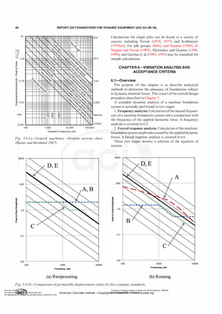
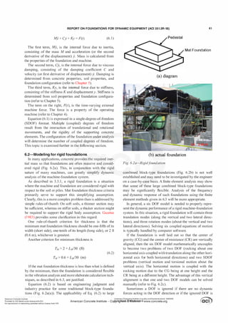
![42 REPORT ON FOUNDATIONS FOR DYNAMIC EQUIPMENT (ACI 351.3R-18)
I
Q)
1J
� C>
a. c
E ·c
<( lll
c C!l
Q) Q)
E .J::
Q)
u c
"' 0
Q. "C
(/) �
i5 :::>
- r.l
.Ill Q)
§ �
N
·c
0
J:
2540
254
25.4
microns
2.54
1 00 1 000 1 0000
Operating Speed, rpm
A: No faults. Typical new equipment.
B: Minorfaults. Correction wastes dollars.
C: Faulty. Correct with in 10 days to save maintenance dollars.
D: Failure is near. Correct with in twodays to avoid breakdown .
E: Dangerous. Shut it down now to avoid danger.
Fig. 6.2b-Vibration criteriaf
or rotating machinery (Blake
1964, as modified byArya et al. 1979).
relatively uncoupled with the dynamic forces. Examples of
ignored DOF would be translation in the direction parallel to
a rotating machine shaft, or rotation about the vertical axis.
6.3-Modeling for flexible foundations
A flexible foundation is any structural configuration that
does not meet rigid foundation requirements. The classic
case of a flexible foundation is a tabletop (Fig. 6.3a) that
uses moment-resisting frames to provide open space for
piping and equipment located directly below the machine.
In this situation, a multi degree of freedom (MDOF) model
should be used.
Equation (6. 1),whenexpressed in MDOF format, becomes
[M] {ji} + [C) {j} + [K) {y} = {F(t)} (6.3)
where [] represents a square matrix and {} represents
a column matrix. The size of the matrixes is equal to the
number ofunknown degrees offreedom.
Structural members (beams, columns, and elevated slabs)
are generally represented in the computer model by pris
matic elastic members/elements, and concrete slabs and
mat foundations are represented by plates or solid elements.
The choice of modeling complexity can vary greatly. Prac
titioners use anything from simple beam elements to three
dimensional solid elements (Fig. 6.3b).
l Fv(t)
+
(a) Vertical translation (b) Coupled horizontal
and rocking
Fig. 6.2c-Aligned f
oundation representation. Note:
Subscript U is horizontal, rp is rocking, and C is cross hori
zontal rocking.
j_
Elevated Slab
: i
i :
� � '
Column ----._.
Mat Foundation
'
'
�
�
-
-
�
-
Fig. 6.3a-Flexiblef
oundation.
Structural stiffness comes from the modeled structural
elements, in addition to specified lumped stiffness values
applied to mat foundation and subgrade (soil) interface
nodes. Structural damping comes from a specified damping
ratio applied to the modeled structural elements, in addition
to specified lumped damping coefficients applied to mat
foundation and subgrade (soil) interface nodes.
The machine can be quite stiff compared with the struc
tural members. If so, the machine can be represented by a
mass point or points concentrated at their centers of gravity
and connected to their supports using rigid links. Solid
elements with matching densities can also be used to simu
late the mass and mass moment of inertia of the machine.
If the equipment is not so stiff as compared with the struc
tural members, as is the case for many large gas compres
sors, its flexibility should be included in the computer model
representation. Mat foundations and pile caps are commonly
proportioned to be rigid to match assumptions made in the
determination of soil or pile impedance.
Impedance ofthe soil or piles should be properly included
in the model to account for the soil-structure interaction
effects. Chapter 5 discusses the impedance ofthe supporting
media. This impedance is nearly always included, either by
Licensee=Chongqing Institute of quality and Standardizationb 5990390
�����":d"b�� �.n r license with ACI
. American Concrete Institute- Copyright� @>fMate'l'laf6L21W�oncrete.org
Noreproduction��or mg perm1tted Without license from IHS](https://image.slidesharecdn.com/351-220912142741-528c03ea/85/351-3r-18-report-on-foundations-for-dynamic-equipment-pdf-44-320.jpg)
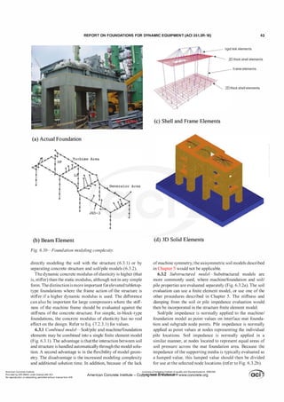
![REPORT ON FOUNDATIONS FOR DYNAMIC EQUIPMENT (ACI 351.3R-18) 45
force rigid link elements
20 thick shell elements
Q mass frame elements
20 thick shell elements
distributed impedance mode
(a) Lumped Impedance (b) Distributed Impedance on a Pile Foundation
Fig. 6.3.2b-Lumped and distributed soil impedance.
damping values by specifying ground modifications and
by changing the proportioning of foundation and structural
members/elements. The use of vibration isolation devices
provides the ability to establish more precise and stable
impedance characteristics, and can capture the benefit of
effectively reducing the foundation vibration level.
Vibration isolators are proprietary devices consisting of
springs, dampers, or both. Springs are used to reduce the stiff
ness otherwise provided by the ground/structure. Dampers
are used to increase the energy dissipation in the machine
foundation system. These devices can be placed between an
inertia block and supporting structural members/elements, as
indicated in Fig. 6.3.3a. They can also be placed between a
tabletop slab and columns as indicated in Fig. 3.3.4 and 3.3.5.
Isolation systems are used for two purposes. The first
purpose is to reduce the transmission ofvibrations between a
supported machine and the surrounding environment. Isola
tors could be used with dynamic machinery, such as forging
hammers, to prevent machine-induced vibrations from
interfering with nearby machines and with worker comfort.
The second purpose is to create a less expensive machine
support when the cost of installing isolators is less than the
cost ofthe larger structural members/elements that would be
required without isolators.
There are three basic spring isolator types used for
dynamic machinery applications: rubber (or elastomeric
materials) pads, steel springs, and air mounts. Rubber pads
are generally the stiffest designs and have a nonlinear load
deflection relationship. Steel springs are less stiff, providing
better isolation but low damping. Air-mount types are the
least-stiff type of isolator.
Most rubbers and steel springs do not have high level of
damping. These designs can be augmented with viscous
dampers, providing higher damping levels up to 40 percent,
depending on the specific application needs.
The effectiveness ofvibration isolators is expressed in two
factors: the transmissibility factor and degree ofisolation.
The transmissibility factor Vp is the peak force trans
mitted to the foundation, FK, divided by the machine's peak
dynamic force F. For rotating and reciprocating machines
Fig. 6.3.3a-Isolator-supportedf
anf
oundation (photo cour
tesy ofGERB Vibration Control Systems, Inc.).
producing a harmonic dynamic force, the transmissibility
factor derived from the equation of motion is indicated in
Fig. 6.3.3b for various values ofdamping ratio D and tuning
ratio ll· The tuning ratio is defined as the forcing frequency
m0 divided by the undamped natural frequency ffi11 of the
machine-inertia block-isolator system. A reduction in the
transmissibility occurs for values ofl] larger than the square
root of2. Stiffness isolation devices typically target 11 values
between 2 to 5. Damping devices are most effective when
11 is near 1 at resonant condition. Note that in the isolation
region for 11 > .Y2, higher damping will result in less isola
tion. Thus, special care should be taken to select suitable
damper devices for optimal design between vibration isola
tion and vibration mitigation near resonance.
The equation for the transmissibility factor, Vp is
expressed as
(6.3.3a)
The isolation efficiency as a percentage, I, is derived from
the transmissibility factor as
I = 100(1 - Vp) (6.3.3b)
American Concrete Institute
Provided by IHS Markit under license with ACI
No reproduction or networking permitted without license from IHS
Licensee=Chongqing Institute of quality and Standardizationb 5990390
American Concrete Institute- Copytri!!lflt�.@11Wlfe¥i11�3!l www.concrete.org](https://image.slidesharecdn.com/351-220912142741-528c03ea/85/351-3r-18-report-on-foundations-for-dynamic-equipment-pdf-47-320.jpg)
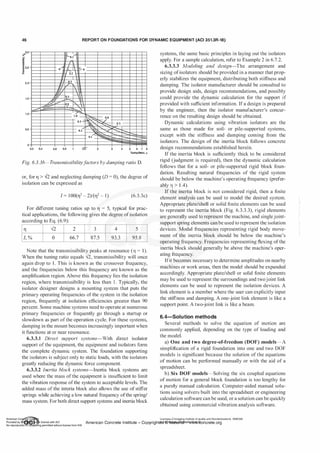
![REPORT ON FOUNDATIONS FOR DYNAMIC EQUIPMENT (ACI 351.3R-18) 47
Fig. 6.3.3.3-Finite element model ofinertia blockand machine (image courtesy ofGERB
Vibration Control Systems, Inc.).
c) Multi DOF models-A solution of the equation of
motion for flexible foundations will, of necessity, involve
finite element analysis computer software. For harmonic
loads, a steady-state approach is efficient. A general-purpose
approach would be to use a modal time history analysis.
6.4.1 Modal trans
f
ormation-This is a transformation of
a coupled multi DOF (MDOF) model into an equivalent
system ofuncoupled single DOF (SDOF) modes. A model of
Q independent degrees offreedom will theoretically result in
Q modes. Each mode is then typically solved using the time
history method (6.4.2). Finally, the results from each mode
are recombined to produce the total system response.
The computational efficiency of a modal transformation
results from the concept that not all modes need to be trans
formed to obtain an accurate result. Additionally, an advan
tageously intermediate result of the transformation is the
frequency (or eigenvalue) and shape (or eigenvector) ofeach
mode. Unlike the more commonly used seismic response
spectrum analysis, the forces for a machine dynamic anal
ysis are known, and the magnitude and direction of ampli
tude results from each mode can be accurately combined.
The efficiency of a modal analysis is improved by deter
mining the least number of modes to reduce computation
time while still achieving an accurate result. The criterion to
select the number of modes to be analyzed depends on two
factors. First, to achieve an accurate calculation of ampli
tude, the total mass participation should be above a stipulated
percentage (usually approximately 95 percent). Second,
enough modes should be included so that the highest modal
natural frequency is greaterthanthe machine frequency plus
a margin. This margin can be determined from a sensitivity
analysis; however, experience indicates the margin should
be approximately 20 percent. For the sample results in Table
6.4. 1 , with an operating speed of 25 Hz, the maximum
modal frequency should be at least the operating speed of
25 Hz times 1 .2 or 30.0 Hz. Thus, 1 5 modes (with an indi
cated maximum frequency of 42 Hz) would suffice. The
minimum mass participation percentage and resonant range
are typically taken from project specifications or internal
procedures.
Table 6.4.1-MDOF analysis options (com parative
time of analysis using typical sam ple data)
Analysis Max frequency, Mass participation,
Analysis time Hz percent
Steady state 3 seconds NA NA
Modal T-H
4 seconds
(5 modes)
15 47
Modal T-H
5 seconds
( 1 5 modes)
42 100
Modal T-H
1 5 seconds
(200 modes)
412 1 00
Modal T-H 1 2 minutes,
(1000 modes) 37 seconds
1 106 1 00
Direct T-H
53 minutes,
NA NA
3 1 seconds
Briefly, the modal transformation begins with modifying
Eq. (6.3) for free vibration by setting the damping C = 0 and
dynamic load, F(t) = 0
[M] {.Y} + [K] {y} = 0 (6.4. 1 a)
Substituting for amplitude and acceleration
{y} = {cp}eiwnt (6.4. lb)
and
{.Y} =
-m,?{<jJ}eiwnt (6.4. 1 c)
Applying this substitution to Eq. (6.4. 1 a), and removal of
the common exponential term results in
[-Mm/] {<jl} + [K] {<jl} = 0 (6.4. 1d)
and rearranging
[K - Mm}] {<jl} = 0 (6.4. 1e)
American Concrete Institute
Provided by IHS Markit under license with ACI
No reproduction or networking permitted without license from IHS
Licensee=Chongqing Institute of quality and Standardizationb 5990390
American Concrete Institute- Cop-ytril!}flte>ct.@1!Wlfe¥i1!l3!l www.concrete.org](https://image.slidesharecdn.com/351-220912142741-528c03ea/85/351-3r-18-report-on-foundations-for-dynamic-equipment-pdf-49-320.jpg)
![48 REPORT ON FOUNDATIONS FOR DYNAMIC EQUIPMENT (ACI 351.3R-18)
For a nontrivial solution, <!> t- 0, the determinant of [K
Mco,?] should be equal to zero, or
IK- Mco}l = 0 (6.4. 1 f)
For relatively low DOF models, a direct solution can be
manually obtained by expanding Eq. (6.4. 1f) to solve for
the natural frequencies, and then solving Eq. (6.4. 1 e) for
the relative amplitudes. For a further discussion related to a
frequency analysis, refer to 6.5.2. For sample applications,
refer to Example 3 (6.7.3) and Example 4 (6.7.4).
For larger DOF models, a direct solution becomes
computationally inefficient. Computer-assisted iterative
techniques can be used on Eq. (6.4. 1 a) to simultaneously
solve for natural frequencies and mode shapes. These tech
niques generally proceed from first (lowest) mode onward
with computational complexity increasing with each higher
mode. To limit computational time, the procedure is usually
halted at a user-specified number ofmodes.
For a detailed description ofmodal transformations, solu
tion procedures, and the recombination of individual mode
results, refer to Biggs (1964) and Bathe ( 1996).
6.4.2 Time history method-The time history solution
method is a resolution of the equation of motion at specific
increments of time. The method begins by calculating the
system mass, damping, and stiffness. Then initial conditions
of displacement, velocity, and acceleration are assumed.
These initial conditions aretypically taken as zero. Values of
displacement, velocity, and acceleration are then calculated
at the subsequent time increment using one of a variety of
available equations.
This method is more flexible than the steady-state method
because the applied force need not be harmonic. This allows
the time history methodto be used for impact type machinery
foundations.
The time history method is commonly used with a modal
transformation using the SDOF form of the time step
equations applied to each mode. As an example, time step
equations based on the constant velocity approach (where
subscripts denote the time step numbers, S) are as follows.
Initial condition where the system is at rest (S = 0):
displacement, y0 = 0 (6.4.2a)
velocity,.Yo = 0 (6.4.2b)
acceleration, ji0 = Fo!M (6.4.2c)
Firsttime step (S = 1):
(6.4.2d)
(6.4.2e)
(6.4.2f)
Subsequent steps (S + 1):
1200
I I I
1000
800
600
400
,!!
200
�
....,_
--- time step= 0.01 s
.t
'1,
--time step = 0.001 s
.I
h;--- I
-� j.[---
�
of
-� -200
! -400
·600
-800
·1000
'
1 /
rll i
.J'..,_ _ _
"' ..L
_
·1200
0.00 0.01 0.02 0.03 0.04 0.05 0.06
Time, s
Fig. 6.4.2-Dynamic loadversus time step.
Ys+I = 2ys -Ys-I + jisTtJ.
2
-,rw;---
�
0.07 0.08
(6.2.4g)
Ys+I = [Fs+I - KYs+I - C(ys+I -Ys)!Tt:,]!M (6.4.2h)
(6.4.2i)
In the preceding equations, the mass M and stiffness K
are constant with time. The dynamic force is evaluated at
each time step and treated as a constant during that time
step. Because of this, the user-selected time step increment
Tt:, should be short enough to accurately describe the loading
function. This effect is illustrated in Fig. 6.4.2.
Because a time history analysis begins at a user-speci
fied initial condition, the transient portion of the response
becomes included in the result. For a harmonic load, this
implies that there should be enough time steps included
to calculate beyond the end of the transient portion of the
response. In addition, the deformation result is reported at
each time step and the user should manually determine the
peak steady-state amplitude. This is normally accomplished
by examining a deformation-time plot ofthe analysis results.
For a sample calculation, refer to Example 5 in 6.7.5.
In place of a modal separation, the time step equations
can be extended to directly deal with MDOF models. Such
a direct time-history analysis can be advantageous for
numerous analysis situations; however, it is not commonly
used for machine foundations because of the slow progress
ofthe calculation (refer to Table 6.4. 1). An additional consid
eration for a direct time-history analysis is that the type of
time step equations to be used becomes significant. For the
analysis of machine foundations, an implicit (iterative) type
oftime step equation would normally apply.
For a detailed description of the time history solution,
refer to Biggs ( 1964) and Bathe (1996).
6.4.3 Steady-state method-This is a closed-form equation
solution based on the assumption of a continuous harmonic
load. The method neglects the (usually not needed) tran
sient portion of the response; however, the method does not
directly calculate natural frequencies.
The steady-state method begins by making the following
substitutions
Licensee=ChongqingInstituteof quality and Standardizationb 5990390
American Concrete Institute- Copyright� @>fMate'l'laf6L21W�oncrete.org](https://image.slidesharecdn.com/351-220912142741-528c03ea/85/351-3r-18-report-on-foundations-for-dynamic-equipment-pdf-50-320.jpg)
![REPORT ON FOUNDATIONS FOR DYNAMIC EQUIPMENT (ACI 351.3R-18) 49
{y} = {A}exp(im0t) (6.4.3a)
(6.4.3b)
{ji} = -w}{A} exp(iffi0t) (6.4.3c)
{F(t)} = {F0}exp(iruat) (6.4.3d)
Applying this substitution to Eq. (6.3), and removal ofthe
common exponential term results in
[-Mw}] {A} + [iru0C] {A} + [KJ {A} = {Fa} (6.4.3e)
Solving for the amplitude A, the resulting solution is
A = {F0}/[K - Mw} + iCwa] (6.4.3f)
If the damping C is zero, then the amplitude A is a real
number representing the peak amplitude L'l and the phase
angle 8 is zero.
If the damping C is nonzero, then the amplitude A is a
complex number (that is, A = a + ib). Resolving this complex
number into the equivalent polar form yields the desired
parameters
amplitude, L'l = modulus (a, b) (6.4.3g)
phase angle, 8 = argument (a, b) (6.4.3h)
For example applications, refer to Example 6 (6.7.6) and
Example 7 (6.7.7).
For a detailed description of the steady-state solution,
refer to Biggs ( 1964) and Kreyszig ( 1967).
6.5-Frequency analysis
A frequency analysis applies to foundations subjected
to harmonic loads and calculates natural frequencies for
comparison with specified acceptance criteria. Methods to
determine natural frequencies are discussed in 6.5.2 and
6.5.3. Acceptance criterion is discussed in 6.5 . 1 .
The term "natural frequency" is commonly used in accep
tance criteria. The term does not stipulate whether the
frequency is damped or undamped. The natural frequency
is typically assumed to be undamped (especially if a modal
transformation is used); however, some practitioners calcu
late a damped frequency because it more accurately repre
sents actual conditions. For low levels of damping, the
undamped and damped natural frequencies are very close.
For high levels of damping, the undamped and damped
natural frequencies are significantly separated and, if the
damping is high enough, there is no resonance. Applicable
equations are as follows.
undamped natural frequency, Wn = JMIK (6.5a)
damped natural frequency, ffid = Wn .J1 - D2 (6.5b)
critical damping, CcR = 2 JMK (6.5d)
Determining the natural frequencies and mode shapes
of the machine foundation system provides information
about the dynamic characteristic of that system. In addi
tion, calculating the natural frequencies identifies the funda
mental frequency, usually the lowest value of the natural
frequencies.
Natural frequencies are significant for the following reasons:
a) They indicate the relative degree of stiffness of the
machine-foundation-soil system.
b) They can be compared with the frequency ofthe acting
dynamic force so that a possible resonance condition may
be prevented. Resonance is prevented when the ratio of the
machine operating frequency to the fundamental frequency
of the machine-foundation system falls outside the undesir
able range (6.5. 1). In many cases, six frequencies are calcu
lated consistent with six rigid body motions of the overall
machine-foundation system. Each of the six frequencies
should be compared with the excitation frequency when
checking for resonance condition.
The significance ofthe mode shapes is as follows:
a) They indicate the deflection pattern that the machine-
foundation system assumes when it is left to vibrate after
the termination of the disturbing force. Generally, it is the
first mode that dominates the vibrating shape, and the higher
modes supplement that shape when superimposed.
b) They indicate the relative degree of the structural
stiffness among various points of the machine-foundation
system-that is, the relationship between different ampli
tudes and mode shapes. If the flexural characteristics of a
foundation are being modeled, a mode shape may indicate
that a portion of the foundation (a beam or a pedestal) is
relatively flexible at a specific frequency. For a system repre
sented by a six degree-of-freedom (DOF) model, the relative
importance ofthe rocking stiffness and the translational stiff
ness can be indicated.
c) They can be used as indicators of sensitivity when
varying the stiffness, mass, and damping resistance of the
machine-foundation system to reduce the vibration ampli
tudes at critical points. A particular beam or foundation
component may or may not be significant to the overall
behavior ofthe system. An understanding ofthe mode shape
can aid in identifying the sensitive components.
Resonance will not be a concern if the natural frequen
cies are well separated from the machine frequency. Ifthere
is a potential for resonance, the engineer should modify
the foundation. If resonance is unavoidable, then a more
refined calculation can be performed. Refined calculations
may include a forced response analysis with a deliberately
reduced level of damping. The size and type of equipment
play an important role in this decision process.
6.5.1 Acceptance criteria f
or f
requency-Acceptance
criteria are typically stated in a project specification, supplier
requirements, client requirements, published criteria, or
internal company criteria.
A specified acceptance criterion is usually expressed in
damping ratio, D = C/CCR (6.5c) terms of the frequency ratio. The frequency ratio is a term
American Concrete Institute
Provided by IHS Markit under license with ACI
No reproduction or networking permitted without license from IHS
Licensee=Chongqing Institute of quality and Standardizationb 5990390
�
OC1
• '
•
'
American Concrete Institute- Copytri!!lflt�.@11Wlfe¥i11�3!l www.concrete.org � CCI j](https://image.slidesharecdn.com/351-220912142741-528c03ea/85/351-3r-18-report-on-foundations-for-dynamic-equipment-pdf-51-320.jpg)
![50 REPORT ON FOUNDATIONS FOR DYNAMIC EQUIPMENT (ACI 351.3R-18)
that relates the operating speed of the equipment to the
natural frequencies ofthe foundation. Frequency ratios may
be based around either W0IW11 or w,/W0 (operating frequency to
natural frequency or its inverse), and engineers or manufac
turers should exercise caution to prevent misunderstandings.
Many companies' acceptance criteria require that the
natural frequency be a minimum of20 to 30 percent removed
from the operating speed. Some firms have used factors as
low as 10 percent or as high as 50 percent.
Frequency ratio is a reasonable design criterion, but one
single limiting value does not fit all situations. Where there
is greater uncertainty in other design parameters (soil stiff
ness, for example), more conservatism in the frequency ratio
may be appropriate. Similarly, vibration problems can exist
even though resonance is not a problem.
There is theoretically one natural frequency for each DOF
in a machine-foundation model. For atypical flexible tabletop
foundation, there could easily be thousands ofDOFs. Because
most DOFs are too insignificant to generate significant reso
nant amplitudes, a minimum mass participation factor is
normally specified to determine which modes are significant
enough to be evaluated. Mass participation is an indicator of
how much mass is mobilized by a particular mode shape.
6.5.2 Calculation of natural f
requencies (direct tech
nique)-The direct technique determines the undamped
natural frequency through a solution derived from the equa
tion of motion. Though the direct technique is fast, it is not
normally found in software as a part ofa coupled steady-state
analysis (6.4.2). However, it is widely applied as a natural
step following a MDOF modal transformation (6.4. 1). The
direct technique is also often used for SDOF models, which
are calculated manually.
For a SDOF system (rigid block-type vertical or torsional
modes), the solution is obtained by rearranging Eq. (6.4. 1 f)
m11 = sqrt[Kv'IM] (6.5.2a)
(6.5.2b)
For a two DOF system (rigid block-type coupled hori
zontal-rocking modes), the following equation is obtained
by expanding Eq. (6.4. 1f). The solution is obtained by
applying a quadratic equation solution
m,4 - [(K,'/M) + (K,/IM"')]w,,2
+ [(K,')(K"'') - (Kc')2]/(M)(M"') = 0 (6.5.2c)
If the soil impedance cannot be considered as linear
over the frequency range of interest, then Eq. (6.5.2b) and
(6.5.2c) will not automatically yield an accurate result. For
nonlinear soil impedance, the assumed frequency value used
to determine the impedance may not match the resulting
calculated value of natural frequency. This situation can
be handled by repeating the calculation of impedance
and natural frequency using different values of assumed
frequency until the assumed frequency matches the calcu
lated:
'
natural frequency. Because ofthe repetitionrequired, it
then becomes more efficient to use the amplitude technique.
I I
3.5 f--. •• • • •• calculated Damping
--- Calculated Damping /2
3 I-- -Calculated Damping I 1000 --11�--+----+------i
� 2.5 t----r---t---;�---r----r--�
.
� 2 t----r---t---�---r----r--�
a.
� 1.5 t----r---t---�---r----r--�
.!!
:!'
� 1 �--�---�--�---r---�--�
0.5 /
�;-..
···:0:�
500 1000 1500 2000 2500 3000
Frequency, rpm
Fig. 6.5.3-Use of reduced damping to detect natural
f
requencies.
6.5.3 Calculation ofnaturalf
requencies (amplitude tech
nique)-The amplitude technique determines undamped
natural frequency through a steady-state solution of the
equation of motion (Eq. (6.4.3f)) by suppressing damping
and applying a fictitious dynamic load over a range of
frequencies. Peaks in the plotted frequency-amplitude
response indicate the desired natural frequency (refer to Fig.
6.5.3). The interpretation of the response curve is typically
completed manually.
This method can be used for most any modeling situation,
but is best implemented when modeling nonlinear soil imped
ance (especially pile groups). To obtain undamped natural
frequencies, damping values should be greatly suppressed.
This is an indirect method because the natural frequen
cies should be determined by the user from amplitude results
over a range of frequencies. The method may be cumber
some to implement for finite element models for frequency
dependent soil/pile impedance.
6.6-Forced response analysis
In a forced response analysis, the equation ofmotion (Eq.
(6. 1) or (6.3)) is solved forthe displacements ofthemachine
foundation system as a function of time. The results of the
forced response analysis include displacements, velocities,
and accelerations. These results are then compared against
allowable limits for acceptance (6.6. 1 ). The allowable limits
are typically applicable at discrete locations (for example,
the equipment bearing, connections to adjacent equipment,
and locations where people may be affected). For flexible
foundation MDOF models, additional nodes are commonly
included in the analysis model for the locations of interest.
The analysis should account for variation in parameters
such as structural stiffness, mass, and soil properties. If
amplitude criteria cannot be met, then the foundation size
will need to be adjusted.
6.6.1 Calculation o
f amplitudes-The peak amplitude
may be calculated by using the methods described in 6.4.
6.6.2 Acceptance criteria f
or amplitude-Acceptance
criteria are typically stated in a project specification, supplier
requirements, client requirements, published criteria, appli
cable legally adopted codes, or internal company criteria.
The engineer should confirm applicable criteria prior to
beginning a design.
American Co-
te Ins Licensee=Chongqing Institute of quality and Standardizationb 5990390
Prov;ded by I
� tn r t;cense w;th ACt American Concrete Institute - Copyright� ®FM!'itel'i!!I'612B,N�oncrete.org
No reproduction � �or mg permitted without license from 1HS](https://image.slidesharecdn.com/351-220912142741-528c03ea/85/351-3r-18-report-on-foundations-for-dynamic-equipment-pdf-52-320.jpg)
![REPORT ON FOUNDATIONS FOR DYNAMIC EQUIPMENT (ACI 351.3R-18) 53
Table 6.6.2.2-Short-term permissible values (DIN 4150-3)
Foundation Foundation Foundation Top complete floor
Type of building (1 to 10 Hz) (10 to 50 Hz) (50 to 100 Hz) (all frequencies)
Industrial and commercial 0.8 in./s (20 mrnls) 0.8 to 1 .6 in./s (20 to 40 m1nls) 1 .6 to 2.0 in./s (40 to 50 mm/s) 1 .6 in./s (40 mrn!s)
Residential 0.2 in./s (5 mrnls) 0.2 to 0.6 in./s (5 to 15 m1nls) 0.6 to 0.8 in./s ( 1 5 to 20 mm/s) 0.6 inls (15 mm/s)
Special or sensitive 0. 1 in./s (3 mrnls) 0.1 to 0.3 in./s (3 to 8 m1nls) 0.3 to 0.4 in.Is (8 to I0 mm/s) 0.3 in.Is (8 mm/s)
Number ofnodes, N = 9
Spacing of nodes, 3 x 3 pattern, 6 ft spacing
Pattern parameter:
L.L/ = (3 each)(--6 flY + (3 each)(O flY + (3 each)(6 ft? = 216 ft2
•
I
6.0 ft
<E------------7
•
X
• • •
Single-node vertical stiffness using Eq. (6.3.2a):
kv = KjN= (2.604 x 1 06 kip/ft)/(9 each) = 289,333 kip/ft
= 4.22 x 10⁶ kN/m
Single-node horizontal stiffness using Eq. (6.3.2b):
k11 = K,!N = (8.400 x 1 05 kip/ft)/(9 each) = 93,333 kip/ft
= 1 .36 x 106 kN/m
Single-node rocking stiffness using Eq. (6.3.2c):
kiJi = [KIJI - kv(2J-/)]!N
= [(3.790 X 10¹¹ kip-ft/rad) - (2.893 X 1 05 kip/ft)(2 16 ft2)]/
(9 each) = 4.21 0 x 1010 kip-ft/rad = 5.71 x 10¹¹ kN-m/rad
Single-node cross stiffness using Eq. (6.3.2d):
kc = KcfN = (5.4 1 8 x 10⁹ kip/rad)/(9 each)
= 6.020 x 10⁸ kip/rad = 2.68 x 1 09 kN/rad
Single-node vertical damping using Eq. (6.3.2e):
Cv = CjN = (1 .480 x I 04 kip-s/ft)/(9 each) = 1644 kip-s/ft
Single-node horizontal damping using Eq. (6.3.2f):
C11 = C,!N = (5.400 x 1 03 kip-s/ft)/(9 each)
= 600 kip-s/ft = 8756.33 kN-s/m
10
�
Q)
"0
:E
c.
E
<{
c
Q)
E
1l 1 .0
"'
c.
"'
Ci
mils
2540
254
25.4
microns
0.1 L-
-
--L..
-
.L..-
.J.....J
L....L..
..I....I.
.J...J:o.-
-
.l.-
--l:>
.......
....J...
.L..J..
.I....J.I 2.54
100 200 500 1 ,000 2,000 5,000 10,000
Frequen cy, rpm
Fig. 6. 6.2.2-Reiher-Meister chart (Richart et al. 1970).
Single-node rocking damping using Eq. (6.3.2g):
ciJI = [CIJI - Cv(2J-/)]!N= [(8.010 x 1 05 kip-ft-s/rad)
- ( 1 .644 x 1 03 kip-s/ft)(2 16 ft2)]/(9 each)
= 49,544 kip-ft/rad = 67 172.64 kN-m/rad
Single-node cross damping using Eq. (6.3.2h):
Cc = CcfN= (2. 170 x 104 kip-s/rad)/(9 each)
= 241 1 kip-s!rad = 10724.66 kN-s/rad
6.7.2 Example 2: Amplitude determination using vibra
tion isolation-This example illustrates a dynamic calcula
tion for a fan supported on an inertia block with vibration
isolators (Fig. 6.3.3a). This example is limited to the vertical
mode. For an actual design, all six modes would need to be
considered.
Fan data:
Machine size: 2.4 m wide by 5.5 m long
Machine speed: W0 = 78.5 rad/s (750 rpm)
Machine mass: 5500 kg
Peak dynamic force: 4600 N
American Concrete Institute
Provided by IHS Markit under license with ACI
No reproduction or networking permitted without license from IHS
Licensee=Chongqing Institute of quality and Standardizationb 5990390
American Concrete Institute- Copytri!!lflt�.@11Wlfe¥i11�3!l www.concrete.org](https://image.slidesharecdn.com/351-220912142741-528c03ea/85/351-3r-18-report-on-foundations-for-dynamic-equipment-pdf-55-320.jpg)
![54 REPORT ON FOUNDATIONS FOR DYNAMIC EQUIPMENT (ACI 351.3R-18)
Permissible peak-to-peak amplitude at foundation: 75 !lm
Permissible tuning ratio: W0IW11 = outside of 0.6 to 1 .4
resonant range
Calculation:
Assume no damping and a rigid inertia block
Select an inertia block: 2.7 m wide by 5.8 m long by
0.46 m thick
Inertia block mass: (2.7 x 5.8 x 0.46 m)(2400 kg/m3) =
1 7,289 kg
In this example, springs are selected, by trial calculation,
that target a natural frequency ofone-third that ofthe fan.
Select springs: Eight each at 19,600 N/cm
Stiffness:
Kv = (8 each)(1 9,600 N/cm)(l OO crn/m) = 1 5,680,000 N/m
Mass:
M= 5500 kg + 17,289 kg = 22,789 kg
Natural frequency using Eq. (6.5a):
0011 = sqrt(KjM) = sqrt[(15,680,000 N/m)/(22,789 kg)]
= 26.2 rad/s
Tuning ratio:
rt = wjw" = (78.5 rad/s)/(26.2 rad/s) = 3 > 1 .4 OK
Degree ofisolation from Eq. (6.3.3c):
I = 1 00(rt2 - 2)/(rt2 - 1) = 1 00(32 - 2)/(JZ - 1) = 87.5%
Transmissibility factor using Eq. (6.3.3b) rearranged:
Vp = 100% - 87.5% = 12.5%
Single (zero-to-peak) displacement amplitude:
SA = F x Vp/abs(Kv - Moo02)
= (4600 N) x 0. 1 25/abs[(1 5,680,000 N/m) - (22,789 kg)
(78.5 rad/s?J = 4.61 x 10⁻⁶ m = 4.61 1-lm = 0. 1 8 1 mil
Double (peak-to-peak) amplitude:
DA = 2(SA) = 2(4.61 !lm) = 9.22 !lm
= 0.363 << 75 !lm = 2.95 OK
Note that nonrigid inertia blocks would require the addi
tional calculation ofnatural frequencies within the block itself.
6.7.3 Example 3: SDOF determination of natural
f
requency-This example illustrates a manual calculation for
vertical translation as described in 6.5.2.
Stiffness: Kv' = 1 1 ,000 lbf/ft
Weight: WT = 3000 lbf
Mass: (WT)/g = (3000 lbf)/(32.2 ft/s2) = 93 lbf-s2/ft
Calculate the natural undamped frequency using Eq.
(6.5.2a):
0011 = sqrt[Kv'IM] = sqrt[(1 1,000 lbf/ft)/(93 lbf-s2/ft)]
= 10.88 rad/s
6.7.4 Example 4: Two DOF determination of natural
f
requency using modal transf
ormation-This example illus
trates a manual calculation for coupled horizontal translation
and rocking as described in 6.4. 1 .
Given impedance at center ofresistance, aligned vertically
with center of gravity:
K, = 8.5 1 8 X 10⁷ lbf/ft
K"' = 5.085 x 10⁹ lbf-ft/rad
Kc = 0 lbf/rad; supposedly a soil-supported mat foundation
Mass: M = 5350 lbf-s2fft
Mass moment of inertia: M"' = 240,000 lbf-s2-ft
Base to center of gravity: h = 3.861 ft
Calculate stiffness at center of gravity:
Ku' = K, = 8.5 1 8 X 1 07 lbf/ft
K'l' = K'l + K,N - 2Kch = (5.085 x 10⁹ lbf-ft/rad) + (8.5 1 8 x
107 lbf/ft)(3.861 ft)2 - 2(0 lbf/rad)(3.861 ft)
= 6.355 x 10⁹ lbf-ft/rad
Kc' = Kc - K,h = (0 lbf/rad) - (8.5 18 x 107 lbf/ft)(3.861 ft)
= -3.289 x 1 08 lbf/rad
Quadratic solution of Eq. (6.5b):
B1 = -(K,'IM) - (K"''IM"')
= -(8.5 1 8 x 10⁷ lbf/ft)/(5350 lbf-s2/ft)
- (6.355 x 1 09 lbf-ft!rad)/(240,000 lbf-s2-ft) = -4.238 x 10⁴ s-2
B2 = [(K,')(K"'') - (Kc'?JI(M)(M"')
= [(8.51 8 x 10⁷ lbf/ft)(6.355 x 109 lbf-ft/rad)
- (-3.289 x 1 08 lbf/rad)2]/(5350 lbf-s2fft)(240,000 lbf-s2-ft)
= 3.370 x 10⁸ s-4
w,12 = {-B1 + �·
B
--=-
12-
-
-
4
-
B
-
2 } I 2
- /2
l-(-4.238 x 1 04 1/s2)
)
-
+�(-4.238x 10⁴ 1/s2 )2 - 4(3.370 x 10⁸ l/s4)
= 3 1, 775 s-2
00111 = 1 78 rad/s
w,/ = {-B1 -�,---
B
--::-
12-
-
-
4
-
B
-
2 }/2
- /2
l-(-4.238 x 10⁴ l!s2)
l
-
-J(-4.238 x 10⁴ l!s2)2 - 4(3.370 x 10⁸ l/s4)
= 10, 605 s-2
oo"z = 103 rad/s
For the first mode, the shape factors derived from Eq.
(6.4. 1 d) are:
<jl1 = -Kc'I(K,' - Moo,12) = -(-3.289 x 1 08 lbf/rad)/
[(8.5 1 8 x 1 07 lbf/ft) - (5350 lbf-s2fft)(1 78 rad/s?J = -3.87
<Pz = 1 .0
For the second mode, the shape factors derived from Eq.
(6.4. 1 d) are:
Licensee=Chongqing Institute of quality and Standardizationb 5990390
American Concrete Institute- Copyright� @>1Mate'l'laf6L21W�oncrete.org](https://image.slidesharecdn.com/351-220912142741-528c03ea/85/351-3r-18-report-on-foundations-for-dynamic-equipment-pdf-56-320.jpg)
![REPORT ON FOUNDATIONS FOR DYNAMIC EQUIPMENT (ACI 351.3R-18) 55
cp1 = -Kc'I(K11' - Mw,}) = -(-3.289 x 1 08 lbf/rad)/
[(8.5 18 x 107 lbf/ft) - (5350 lbf-s2/ft)(103 rad/s?J = 1 1 .58
<P
2
= 1 .0
6.7.5 Example 5: SDOF determination ofamplitude using
time-history method-This example illustrates a manual
calculation for peak vertical translation as described in 6.4.2.
Magnitude of force: Fv = 1000 lbf
Frequency afforce: W0 = 3 14. 16 rad/s (3000 rpm)
Mass: M= 2960 lbf-s2/ft
Stiffness: Kv' = 135,300,000 lbf/ft
Damping coefficient: Cv' = 36,840 lbf-s/ft
Select time step (Tt.):
cycle time = (l/3000 min/rev)(60 s/min) = 0.02 s
Time step: Tt. = (cycle time)/10 = (0.02 s)/10 = 0.002 s
Calculate the initial conditions (S = 0) using Eq. (6.4.2a)
through (6.4.2c):
F0 = Fveos(W0t) = (1000 lbf)cos(3 14. 16 rad/s x 0 s) = 1000 lbf
Yo = 0
Yo = 0
ji0 = F01Mv = (1000 lbf)/(2960 lbf-s2/ft) = 0.338 ft/s2
Calculate the first time step (S = 1) using Eq. (6.4.2d)
through (6.4.2f):
t1 = 0 + Tt. = 0.002 s
F1 = Fveos(w0t1) = (1000 lbf)cos(3 14. 16 rad/s x 0.002 s) =
809 lbf
y1 = y0 + 0.5ji0Tt.2 = 0 + 0.5(0.338 ft/s2)(0.002 s? = 6.76 x
1 0-7 ft
ji1 = [F1 -Ky1 - C(y1 -y0)1Tt.]IM= [(809 lbf) - (135,300,000
lbf/ft)(6.76 x 1 0-7 ft) - (36,840 lbf-s/ft)(6.76 x 10-7 - 0 ft) I
(0.002 s)]/(2960 lbf-s2/ft) = 0.238 ft/s2
Y1 = (y1 - Yo)ITt. + YI Tt./2 = (6.76 x 1 0·7 - 0 ft)/0.002 s +
(0.238 ft/s2)(0.002 s)/2 = 5.76 x 10·4 ft/s
Calculate the second time step (S = 2) using Eq. (6.4.2g)
through (6.4.2i):
t2 = t1 + Tt. = (0.002 s) + (0.002 s) = 0.004 s
F2 = Fveos(w0t
2
) = (1000 lbf)cos(3 14. 1 6 rad/s x 0.004 s) =
309 lbf
y2 = 2y1 -y0 + ji1Tt.2 = 2(6.76 x 10⁻⁷ ft) - (0) + (0.238 ft/s2)
(0.002 s)2 = 2.30 x 10⁻⁶ ft
ji2
= [F
2
-Ky2
- C(y2
-y1)1Tt.]IM= [(309 lbf) - (135,300,000
lbf/ft)(2.30 x 1 o-6 ft) - (36,840 lbf-s/ft)(2.30 x 1 o-6 - 6.76 x
l 0-7 ft)/(0.002 s)]/(2960 lbf-s2/ft) = -0.0 1 1 ft/s2
Y2 = (Y2
- Yl)!Tt,. + Y2Tt.l2 = (2.30 X 10⁻⁶ - 6.76 X 1 0-7 ft)/
(0.002 s) + (-0.0 1 1 ft/s2)(0.002 s)/2 = 8.01 x 10⁻⁴ ft/s
The repeated calculation is typically performed on a
spreadsheet as follows·
Dynamic Accelera-
Time, s load, lbf Deflection, ft Velocity, ft/s tion, ft/s2
0.0000 1 000 0.000 0.000 0.338
0.0020 809 6.757 X J0-{)7 5.73J X J0-{)4 0.235
0.0040 309 2.293 X 1 0-{)6 7.98J X J0-{)4 -0.01 0
0.0060 -309 3.868 X 1 0-{)6 5.003 X J0-{)4 -0.287
0.0080 -809 4.292 X 1 0-{)6 -2.535 X 10-{)4 -0.466
0.0100 -1000 2.854 X J0-{)6 -J .J74 X J 0-{)3 -0.454
0.0120 -809 -4.007 X 10-{)7 -1 .859 X J 0-{)3 -0.232
0.0140 -309 -4.583 X 10-{)6 -1 .962 X J 0-{)3 0.129
0.0160 309 -8.247 X 10-{)6 -J .334 X J 0-{)3 0.498
0.01 80 809 -9.9J9 X 10-{)6 -J .08J X J 0-{)4 0.728
Dynamic Deflection, Accelera-
Time, s load, kN !lm Velocity, mm/s tion, m/s2
0.0000 4.448 0.000 0.000 0.103
0.0020 3.599 0.206 0. 1 74 0.072
0.0040 1 .375 0.699 0.243 -0.003
0.0060 -1 .375 1 . 1 79 0. 152 -0.087
0.0080 -3.599 1 .308 -0.077 -0. 142
0.0100 -4.448 0.870 -0.358 -0. 1 38
0.0120 -809 -0. 1 22 -0.567 -0.07 1
0.0140 -309 -1.397 -0.598 0.039
0.0160 309 -2.5 14 -0.407 0.152
0.0180 809 -3.023 -0.033 0.222
Theresulting deformationtimeplotis as follows inFig. 6.7.5.
The steady-state peak amplitude is read from the spread
sheet at a time period after the observable transient response
has subsided.
single amplitude (at t = 1 .8700 s) = 6.749 x 1 0-6 ft
= 0.08 mils (2 11m)
The use ofa shorter time step would result in an amplitude
that matches the corresponding result in Example 6 (6.7.6).
6.7.6 Example 6: SDOF determination ofresponse using
steady-state method-This example illustrates a manual
calculation for the peak vertical translation response as
described in 6.4.3 without the use ofcomplex arithmetic.
Magnitude offorce: Fv = 1000 lbf
Frequency of force: W0 = 3 14. 1 6 rad/s (3000 rpm)
Mass: M = 2960 lbf-s2/ft
Stiffness: Kv = 135,300,000 lbf/ft
Damping coefficient: Cv = 36,840 lbf-s/ft
Calculate parameters based on Eq. (6.4.3f):
a = Kv - Mw} = (135,300,000 lbf/ft)
- (2960 lbf-s2fft)(3 14. 16 rad/s? = -1 .565 x 108 lbf/ft
b = -Cvffio = -(36,840 lbf-s/ft)(3 14. 1 6 rad/s)
= -1 . 157 X 1 07 lbf/ft
Calculate the peak amplitude:
L1v = F/sqrt[a2 + b2] = ( 1000 lbf)/sqrt[(-1 .565 x 108 lbf/ft)2 +
(-1 .157 X 1 07 lbf/ft?] = 6.358 X 1o-6 ft = 0.076 milS = 1 .93 11m
Calculate the phase angle (with both a and b negative):
8v = 180 - arctan[b/a] = 180 - arctan[(-1 . 1 57 x 1 07 lbf/ft)/
(-1 .565 x 108 lbf/ft)] = -175.779 deg
American Concrete Institute
Provided by IHS Markit under license with ACI
No reproduction or networking permitted without license from IHS
Licensee=Chongqing Institute of quality and Standardizationb 5990390
American Concrete Institute- Copytri!!lflt�.@11Wlfe¥i11�3!l www.concrete.org](https://image.slidesharecdn.com/351-220912142741-528c03ea/85/351-3r-18-report-on-foundations-for-dynamic-equipment-pdf-57-320.jpg)
![56 REPORT ON FOUNDATIONS FOR DYNAMIC EQUIPMENT (ACI 351.3R-18)
1.5E-05 �---,-----,-------,----,-------,----,
l.OE-05 hi-�J---+---+--+--+----j
.,
.
E
5.0E-06 HU.--1-Itll--ll-lh.HI-.JH-ft-;II+A-+tl-ft-Atf+ll-ft-iltliHIHI""fti
� O.OE+OO
}
II
v
c
-5.0E-o6 -I-U--U--11--Iii--!--V-IIJ-V--f.--li-U-f-#--V-ll-li--ll-f--v-11t--V--f--tll--f--H+-IH
-l.OE-05 f-1-
--f--
-
+--
-
�
+-
-
-
+
-
-
+
-
-
+
-
-
-
-l.SE-05 .I---J---+----+-----+------1------<
M U U U U U U
Time.s
Fig. 6. 7.5-Time-history amplitudeplot.
6.7.7 Example 7: Two DOF determination of response
using steady state method-This example illustrates a
manual calculation for peak horizontal translation and
rocking response as described in 6.4.3.
Given impedance at center ofresistance·
Ku = 5.634 X 10⁷ lbf/ft Cu = 1 .441 x 105 lbf-s/ft
Kill = 3.636 x 10⁹ lbf-ft/rad Cll/ = 7.225 x 10⁶ lbf-ft-s/rad
Kc = --4.772 x 1 07 lbf/rad Cc = -6.395 x 1 04 lbf-s/rad
Given inertia about center ofgravity:
IM = 2956 lbf-s2fft IMill = 62, 183 lbf-s2-ft
Given height from center ofresistance to center ofgravity:
h = 3.418 ft
Given machine properties:
(!)0 = 3 14 rad/s (3000 rpm)
Force: Fu = 1000 lbf
Moment: Fill = 0 lbf-ft
The following equations are from Fang (199 1), and modi
fied to include damping:
B1 = (K,) - (M)(roo? + i(CH)(ro0) = (5.634 x 10⁷ lbf/ft)
- (2956 lbf-s2/ft)(314 rad/sf + i(1.441 x 10⁵ lbf-s/ft)(3 14 rad/s)
= -2.354 X 10⁸ + i4.527 X 107 lbf/ft
B2
= (Kc) - (Ku)(h) + i(Cc)(ffi0) - i(Cu)(h)(roo)
= (--4.772 x 10⁷ lbf/rad) - (5.634 x 1 07 lbf/ft)(3.418 ft)
+ i(-6.395 x 10⁴ lbf-s/rad)(3 14 rad/s) - i(l .441 x 105 lbf-s/ft)
(3.418 ft)(3 14 rad/s) = -2.403 x 10⁸ - il .748 x 1 08 lbf/rad
B3 = (Kill) - (Mil!)(roo? + (Ku)(h)2 - (2)(Kc)(h) + i(Cill)(roa)
+ i(Cu)(ro0)(h? - i(2)(Cc)(ro0)(h) = (3.636 x 10⁹ lbf-ft/rad)
- (62,183 lbf-s2-ft)(3 14 rad/s)2 + (5.634 x 10⁷ lbf7ft)(3.418 ft)2
- (2)(--4.772 x W lbf7rad)(3.418 ft) + i(7.225 x 10⁶ lbf-ft-s/rad)
(3 14 rad/s) + i(1 .441 x 1 05 lbf-s/ft)(3 14 rad/s)(3 .41 8 ft?
- i(2)(-6.395 x 10⁴ lbf-s/rad)(3 14 rad/s)(3.418 ft)
= -1.5 17 x 109 + i2.936 x 109 lbf-ft/rad
B4 = (BJ)(B3) - (B2
?= (-2.354 X 10⁸ + i4.527 X 107 lbf/ft)
(-1.5 1 7 x 10⁹ + i2.936 x 109 lbf-ft/rad)
-(-2_403 X 108 - il .748 X 1 08 lbflrad? = 1 .970 X 1 017 -
i8.440 X 1 017 lbf2
Au = [(B3)(Fu) - (B2
)(FIJ!)]/B4
= [(-1.517 X 1 09 + i2.936 X
J09 Jbf-ftlrad)(l00D lbf) - (-2.403 x 10⁸ - il.748 x WS lbflrad)
(0 lbf-ft)]/(1 .970 X 1017 - i8.440 X 1017 lbf2)
= -3.697 x 1 0·6 - i9.341 x 10-7 ft
Amplitude:
1'1u = modulus (Au) = sqrt[a2 + b2] = sqrt[(-3.697 x 1 0-6 ft)2
+ (-9.341 x 10⁻⁷ ft?J = 3.81 x 10⁻⁶ ft
Phase angle:
8, = argument (A,), with both a and b being negative:
= -180 + arctan[b/a] = -180 + arctan[(-9.341 x 1 0-7 ft)/
(-3.697 X 10⁻⁶ ft)] = -165.8 deg
All! = [(BJ)(Fil/) - (B2
)(F,)]/B4 = [(-2.354 X 10⁸ + i4.527 X
1 07 lbf/ft)(O lbf-ft) - (-2.403 X 10⁸ - il .748 X 1 08 lbf/rad)
(1000 }bf))/(1 .970 X 1017 - i8.440 X 1 017 lbf2)
= -1.334 x 1 0-7 + i3. 159 x 10-7 ft
Amplitude:
1'1JI = modulus (All!) = sqrt[a2 + b2]= sqrt[(-1 .334 x 10-7 ft?
+ (3.159 x 10⁻⁷ ft?J = 3.43 x 10⁻⁷ n = o.1o5 J-lm
Phase angle:
8lll = argument (All!), with a positive and b negative:
= arctan[b/a) = arctan[(3.159 x 10⁻⁷ ft)/(-1 .334 x 1 0-7 ft)] =
-67.1 deg
CHAPTER 7-DESIGN AND MATERIALS
7.1-0verview of design methods
This section presents general considerations andan overview
of three commonly used methods for the design of dynamic
equipment foundations: the rule-of-thumb method, the equiva
lent static loading method, and the dynamic analysis method.
7.1.1 General considerations-The objectives of the
machine foundation design are to assess the dynamic
response of the foundation and verify compliance with the
required vibration and structural performance criteria.
Machine foundation design typically includes the
following steps:
a) Develop a preliminary size for the foundation using
rule-of-thumb approaches (7.1.2.1) or equivalent static
loading method (7. 1 .2.2), past experience, machine manu
facturer recommendations, and other available data.
b) Calculate the vibration parameters, such as natural
frequency, amplitudes, velocities, and accelerations, for the
preliminarily sized foundation (7. 1 .2.3).
c) Verify that these calculated parameters do not exceed
generally accepted limits or project specific vibration perfor
mance criteria (7. 1 .2.3).
d) If necessary, incorporate appropriate modifications in
the foundation design to reduce vibration responses to meet
the specified vibration performance criteria and cost.
e) Check the structural integrity ofthe concrete foundation
and machine-mounting system.
f) If foundation sizes required are excessively large, deter
mine if vibration mitigation measures such as vibration
isolation are required or beneficial.
Preventive measures to reduce vibrations are generally
less expensive when incorporated in the original design than
remedial measures applied after machinery is in operation.
The following are some common means that can be used
separately or combined to reduce vibrations:
Licensee=Chongqing Institute of quality and Standardizationb 5990390
American Concrete Institute- Copyright� @>fMate'l'laf6L21W�oncrete.org](https://image.slidesharecdn.com/351-220912142741-528c03ea/85/351-3r-18-report-on-foundations-for-dynamic-equipment-pdf-58-320.jpg)
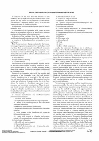
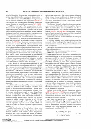
![REPORT ON FOUNDATIONS FOR DYNAMIC EQUIPMENT (ACI 351.3R-18) 61
Dynamic concrete modulus may also be determined by
other appropriate means (Neville 1997; BS 8 1 1 0-2; USACE
EM 1 1 10-2-605 1 ; Popovics 2008).
Dynamic modulus of elasticity is applicable to only
response spectrum and time-history dynamic analysis load
cases (as theyhave rapid rate ofchanges in the loads). There
is no common agreement to use it in the static equivalent
analysis, steady-state dynamic analysis, or both, unless
required by machine manufacturers.
In the load combinations composed of static and dynamic
load cases, the engineer may need to investigate and develop
design values by two separate analyses (static with static
modulus/properties and dynamic with dynamic modules/
properties ofmaterial).
7.2.3.2 Concrete material damping-Concrete mate
rial damping typically does not have much impact on the
vibration performance of block-type foundations. Concrete
material damping is very small compared to soil damping
(geometric damping plus soil material damping). In that
case, the material damping of concrete may be neglected.
In contrast, concrete material damping can play an impor
tant role in vibration performance of elevated tabletop-type
foundations. For foundation vibration analysis, concrete
material damping ratio is typically taken as 2 percent due to
low stress levels in the foundations. ASCE Task Committee
(1987) recommends that damping of concrete structural
members/elements should be taken as no greater than 2
percent. Some engineers conservatively use 1 percent of
concrete material damping for the dynamic equipment that
is highly vibration-sensitive.
7.2.3.3 Concrete Poisson s ratio-For an isotropic and
linear-elastic material, Poisson's ratio is constant; however,
in concrete, Poisson's ratio may be influenced by specific
conditions. For stresses for which the relationship between
the applied stress and the longitudinal strain is linear,
however, the value of Poisson's ratio for concrete is approxi
mately constant. Depending on the properties ofthe aggregate
used, Poisson's ratio of concrete lies generally in the range
of 0. 1 5 to 0.22 when determined from strain measurements
under a compressive load. The value ofPoisson's ratio under
tensile load appears to be the same as in compression. Existing
research (Popovics 2008) reports that the dynamic and static
values ofPoisson's ratio are not strongly related to each other
and dynamic Poisson's ratio can be as high as 0.25. However,
foundation designers commonly use 0. 15 to 0.2 as concrete
Poisson's ratio for foundation dynamic analysis.
7.2.3.4 Moment of inertia of members-Gross moment
of inertia (!g) calculated based on an uncracked concrete
section is typically used for modeling ofblock-type founda
tions and tabletop foundations because of massive member
size and low stresses. If cracked members are to be consid-
ered, however, reduced moment of inertia as determined in
accordance with 6.6.3 ofACI 3 1 8-14 is typically used.
7.3-Reinforcement
7.3.1 Reinf
orcing steels-As with most construction,
ASTM A615/A615M Grade 60 reinforcing steel is most
commonly used for dynamic machine
_
foundati?_lls
,
- (]_�od
design practice requires particular attention to the detailing
of the reinforcement, including proper development of the
bars well into the block of the concrete, avoidance of bar
ends in high-stress regions, and appropriate cover.
Where concrete is exposed to severe weather, sulfate
exposure, or both, reinforcing steel may require corrosion
protection. Depending on the corrosion severity, protec
tion measures could include use of epoxy-coated, metallic
coated, and solid metallic reinforcing bars (such as galva
nized steel bars and stainless steel bars); use of FRP bars;
use ofcorrosion inhibitors (such as calcium nitrates or other
organic corrosion inhibitors); use of concrete membranes or
concrete sealers; or providing catholic protection.
7.3.2 Minimum reinforcing requirements-Industry prac
tice on the minimum reinforcement used varies widely,
depending on type ofdynamic equipment foundations, type
ofmembers, and the preference offirms.
In foundations thicker than 4 ft (1.2 m), the engineer
commonly uses the minimum reinforcement suggested in
ACI 207.2R for mass concrete. Section 7. 12.2 ofACI 350-06
provides more recent alternative criterion, which states that
concrete sections that are at least 24 in. (600 mm) thick may
have the minimum shrinkage and temperature reinforcement
based on a 12 in. (300 mm) concrete layer at each face.
For large turbine generator foundations, some firms
specify a minimum reinforcement of3.l lbf/ft3 (50 kgf/m3 or
0.64 percentby volume) for pedestals and 1 .9 lbf/ft3 (30 kgf/
m3 or 0.38 percent by volume) for foundation slabs. Others
prefer to use a larger minimum reinforcement of 3.1 lbf/ft3
(50 kgf/m3) in the foundation slabs. Some European equip
mentvendorsrequirethe use ofmultiple layers ofreinforcing
steel spaced in all three directions. For compressor blocks,
some firms suggest 1 percent reinforcement by volume
consisting of multi-layers of reinforcement instead of rein
forcement only at faces of concrete and may post-tension
the block. Many engineers recommend additional reinforce
ment, such as hairpin bars, around embedded anchor bolts
to ensure long-term performance. The criteria and presenta
tions in ACI 351 .2R for static equipment also can be applied
to dynamic equipment foundations.
Design of forging hammer foundations considers a stati
cally equivalent load determined from the impact energy
and characteristics ofthe forging process in addition to other
design basis loads. Minimum reinforcement of the founda
tion block is set at 1 .56 lbf/ft3 (25 kgf/m3) or 0.32 percent
by volume. This reinforcement should be distributed in all
three directions throughout the foundation block. The upper
layer of steel should be capable of resisting 1 percent of the
statically equivalent load applied in any horizontal direction.
Bending and shear effects should be addressed in the layout
and design of the reinforcement. In large hammer founda
tions, reinforcement is often installed in all three orthogonal
directions and diagonally in the horizontal and vertical
planes. Suitable development of the reinforcement is very
important. Excessive reinforcement can create constructa
bility and quality problems and should be avoided.
7.3.3 Common reinf
orcingsteeldesignpracticef
orconcrete
pedestals-ACI 351 .2R provides a summary of commonly
American Concrete Institute
Provided by IHS Markit under license with ACI
No reproduction or networking permitted without license from IHS
Licensee=Chongqing Institute of quality and Standardizationb 5990390
�
OC1. ..
.
•
American Concrete Institute- Copytri!!lflt�.@11Wlfe¥i11�3!l www.concrete.org � CCI j](https://image.slidesharecdn.com/351-220912142741-528c03ea/85/351-3r-18-report-on-foundations-for-dynamic-equipment-pdf-63-320.jpg)
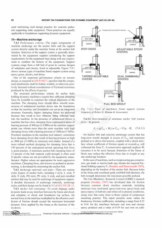
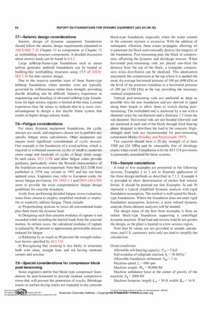
![REPORT ON FOUNDATIONS FOR DYNAMIC EQUIPMENT (ACI 351.3R-18) 65
Distance ofmachine shaft centerline to top of foundation:
dmf= 10 ft
Concrete 28-day strength:};,' = 4000 psi
Concrete unit weight: Yc = 150 lbf/ft3
Dynamic acceptance criteria:
Mass ratio offoundation to machine: 3
Frequency separation: Fundamental frequencies of foun
dation should be 25 percent away from the machine oper
ating speed of 600 rpm.
Vibration limit: Peak-to-peak (p-p) displacements at the
center of gravity ofthe machine should not exceed 1.5 mils
at machine operating speed of 600 rpm under a machine
unbalance force of2000 lbf.
7.10.1 Example 1: design by the rule-of-thumb method
Initial length of foundation mat:
LM = 1 ft + Lmr+ 1 ft = 1 ft + 30 ft + 1 ft = 32 ft
(for typical clearance)
Initial width of foundation mat:
BMI = 1 ft + Bnif+ 1 ft = 1 ft + 1 6 ft + 1 ft = 1 8 ft
(for typical clearance)
Select initial mat foundation thickness:
According to the four minimum thickness proportioning
rule-of-thumb rules:
TMI = LM/10 = 32 ft/10 = 3.2 ft
TM2 = BM,/5 = 1 8 ft/5 = 3.6 ft
TM3 = 2 ft
TM4 = BM,/30 + 2 ft = 1 8 ft/30 + 2 ft = 2.6 ft
Select TM2 = 3.6 ft, which is equal or greater than all the
aforementioned values.
Check the initialwidth adequacy using the following rule
of-thumb rule:
BM_req = 1.5 x (dmr+ TM2) = 1 .5 x (10 ft + 3.6 ft) = 20.4 ft> BMI
As the minimum foundation width of 20.4 ft exceeds the
initial width of 18 ft, and considering the site space restric
tion, revise foundation width to BM = 20 ft.
Recheck mat foundation thickness due to larger width:
TM_req = BM/5 = 20 ft/5 = 4 ft; revise foundation thickness to
TM = 4 ft.
Check foundation mass (or weight) adequacy:
Weight ofconcrete mat foundation:
Tfr= (LM X BM X TM) X Yc = (32 ft X 20 ft X 4 ft) X 150 lbf/ft3
= 384,000 lbf
Mass (or weight) ratio ofconcrete foundation to machine:
MR = W
JW," = 384,000 lbf/98,000 lbf= 3.9 > 3
Thus, the foundation with size selected meets the minimum
mass ratio requirement.
This example demonstrates that the rule-of-thumb method
is simple and can be easily applied to establish the initial
foundation size. The initial foundation sizes can be veri
fied using the equivalent static loading method described in
7. 1 .2.2 and Example 2 (7. 1 0.2).
7.10.2 Example 2: eqidvalenislaiz'cT
oading method
Vertical pseudo-dynamic design force:
Fpv = 0.5 X W111 = 0.5 X 98,000 lbf= 49,000 lbf
Lateral and longitudinal pseudo-dynamic design forces:
Fp/ = 0.25 X W111 = 0.25 X 98,000 lbf= 24,500 lbf
Overturning moment:
M0 = Fpl X (dnif+ TM) = 24,500 lbf X (10 ft + 4 ft)
= 343,000 lbf-ft
Resisting moment:
M,'eS = (W,, + Wr) X BM/2 = (98,000 lbf+ 384,000 lbf) X 20 ft/2
= 4,820,000 lbf-ft
Overturning check:
M,-es > Mo OK
Maximum bearing pressure:
Pmax = (Tfr+ W,, + Fpv)f(LM X BM)
= (384,000 lbf + 98,000 lbf + 49,000 lbf)/(32 ftx 20 ft)
= 0.83 ksf < 0.5 x P011 = 2.5 ksf
Note that the maximum soil bearing pressure due to
normal operating is 0.83 ksf, which is less than half of the
allowable soil bearing capacity of 5 ksf.
Static soil stiffness:
Ks = ks X (LM X BM)
= 36 lbf/in.3x (32 x 12 in. x 20 x 12 in.) = 3,3 1 8,000 lbf/in.
Maximum foundation settlement:
Smax = (Tfr+ Wm + Fpv)fKs
= (384,000 lbf+ 98,000 lbf+ 49,000 lbf)/(3,3 18,000 lbf/in.)
= 0. 1 6 in. < Sail (= 1 in.)
Note that the equivalent static loading method can
verify the foundation configuration design based on the
soil bearing, settlements, and foundation stability, but the
dynamic analysis method (Example 3a and 3b [7. 10.3 and
7 . 1 0.4]) will be needed for evaluation of the foundation
dynamic performance acceptance.
7.10.3 Example 3a: dynamic analysis method-frequency
check
Frequency acceptance criteria:
Fundamental frequencies Wu of the foundation system
should be 25 percent away from the machine speed of 600
rpm (10 Hz).
Wu < 0.75 x 600 rpm = 7.5 Hz
or
Wu > 1 .25x600 rpm = 12.5 Hz
The soil spring stiffness was calculated at the center of
resistance under 600 rpm using commercial software:
Soil vertical stiffness Kv = 2.629 x 10⁸ lbf/ft
Soil horizontal stiffness KH = 2.467 x 10⁸ lbf/ft
Soil rocking stiffness KR = 5.292 x 10¹⁰ lbf-ft/rad
Soil cross stiffness Kc = --4.933 x 10⁸ lbf/rad
American Concrete Institute
Provided by IHS Markit under license with ACI
No reproduction or networking permitted without license from IHS
Licensee=Chongqing Institute of quality and Standardizationb 5990390
American Concrete Institute- Copytri!!lflt�.@11Wlfe¥i11�3!l www.concrete.org](https://image.slidesharecdn.com/351-220912142741-528c03ea/85/351-3r-18-report-on-foundations-for-dynamic-equipment-pdf-67-320.jpg)
![66 REPORT ON FOUNDATIONS FOR DYNAMIC EQUIPMENT (ACI 351.3R-18)
Total mass ofthe foundation system:
m = (WJ+ W,11)/g = (384,000 lbf+ 98,000 lbf)/32. 1 7 ft/s2 =
14,982.9 lbf-s2/ft
Calculatetheundampedvertical frequency using Eq. (6.4. lf):
Wv = sqrt[Kv!M] = sqrt[(2.629x 10⁸ lbf/ft)/(14,982.9 lbf-s2/ft)]
= 132.5 rad/s = 2 1 . 1 Hz
Calculate theundampedlateralfrequencyusing Eq. (6.4. 1 f):
w11= sqrt[KHIM] =sqrt[(2.467 x 10⁸ lbf/ft)/(14,982.9 lbf-s2/ft)]
= 128.3 rad/s = 20.4 Hz
Mass moment of inertia about the rocking axis at center
ofgravity:
IR = w
f x [(BM2 + TM2)11 2 + (h - TMI2?]1g + w,ll
X (dmf+ TM - h)2/g
= 384,000 lbf x {[(20 flY + (4 ft?J/12 + (4.44 ft - 4 ft?}/32. 17
ft/s2 + 98,000 lbf x (10 ft + 4 ft - 4.44 ftf/32. 1 7 ft/s2
= 763,281 lbf-s2-ft
CalculatetheundampedrockingfrequencyusingEq. (6.4. 1f):
w$ = sqrt[KRIIR] = sqrt[(5.292 x 10¹⁰ lbflft)/(763,281 lbf-s2fft)]
= 263.3 rad/s = 41.9 Hz
Calculate the coupled horizontal translation and rocking
frequency as described in 6.4. 1 :
Distance of base to center of gravity of foundation system:
h = 4.44 ft
Calculate stiffness at center ofgravityoffoundation system:
KH' = KH = 2.467 X 10⁸ lbf/ft
KR' = KR + KH x h2 - 2 x Kc x h
= 5.292 x 10¹⁰ lbf-ft/rad + 2.467 x 10⁸ lbf/ft
X (4.44 ft? - 2 X (-4.933 X 10⁸ lbf/rad) X 4.44 ft
= 6.22 x 1 010 lbf-ft/rad
K'c=Kc-KHxh=-4.933 x 10⁸Jbf/rad-2.467x 108lbf/ftx4.44ft
= - 1 .59x 109 lbf-ft/rad
Quadratic solution ofEq. (6.5b):
B1 = - K'H!M- K'R!JR = -(2.467x 10⁸ lbflft)/(14982.9 lbf-s2/ft)
- (6.22x 10¹⁰ lbf-ft/rad)/(763,28l lbf-s2-ft) = -9.79x 1 04 s-2
B
2
= (K'H x K'R - K'c2)/(M x IR) = [2.467 x 10⁸ lbf/ft x 6.22
x 1 010 lbf-ft/rad) - (-1 .59x 109 lbf-ft/rad)2]/(14,982.9 lbf-s2/
ft x 763,28l lbf-s2-ft) = 1 . 12 x 109 s-4
w? = [-B1 + (B12 - 4 x B
2
)112] /2 = {-(-9.79 x 1 04 s-2) +
[(-9.79 x 10⁴ s-2? - 4 x 1 . 12 x 109 s-4]112}/2 = 84,678.67 s-2
w1 = 291 rad/s = 46.3 Hz
wl = [-B1 - (B12 - 4 x B
2
)112]/2 = {-(-9.79x l 04 s-2) +
[(-9.79x l04 s-2)2 - 4 x 1 . 12 x 109 s-4]112}/2 = 13,23 1 .78 s-2
w
2
= 1 15 rad/s = 1 8.3 Hz
T:he lowest fundamental frequency is the coupled hori
zontal translation and rocking frequency (18.3 Hz), which is
sufficiently higher than 12.5 Hz (125 percent ofthe machine
speed). Therefore, this foundation design meets the dynamic
fre�uency acceptance criteria.
7.10.4 Example 3b: Dynamic analysis method-calcula
tion ofvibration magnitudes-All design input are the same
as in Examples 1 , 2, and 3a except that the foundation should
meet the following allowable vibration magnitude criterion:
Vibration displacements, p-p, at the center of gravity of
the machine :S 1 .5 mils at machine operating speed of 600
rpm under a dynamic machine unbalance force of 2000 lbf.
The soil spring stiffness was calculated at the center of
resistance under 600 rpm using software:
Soil vertical stiffness: Kv = 2.629 x 10⁸ lbf/ft
Soil horizontal stiffness: KH = 2.467 x 10⁸ lbf/ft
Soil rocking stiffness: KR = 5.292 x 10¹⁰ lbf-ft/rad
Soil cross stiffness: Kc = -4.933 x 10⁸ lbf/rad
Soil vertical damping: Cv = 3.9 x 1 06 lbf-s/ft
Soil horizontal damping: CH = 2.522 x 10⁶ lbf-s/ft
Soil rocking damping: CR = 4.683 x 10⁸ lbf-ft-s/rad
Soil cross damping: Cc = -5.044 x 1 06 lbf-s/rad
Distance ofbase to center of gravity: h = 4.44 ft
Dynamic forces at center of gravity of foundation system:
Unbalanced forces:
Fv = 2000 lbf(vertical) and F11 = 2000 lbf
(Lateral) dynamic moment:
FR = F0 X (14 ft-h) = 19,120 lbf-ft
Frequency of force:
W0 = 600 rpm = 62.8 rad/s
Apply Eq. (6.4.3f) to calculate the complex vertical
amplitude:
Av = F,,[Kv - M x w} + i x Cv x W0] = (2000 lbf)/[2.629 x
1 08 lbf/ft - 14,982.9 lbf-s2/ft x (62.8 rad/s)2 + i x 3.9 x 1 06
lbf-s/ft X 62.8 rad/s] = (4.012 X 1 0·6 - i X 4.826 X 10·6) ft
Apply Eq. (6.4.3g) to calculate the peakvertical amplitude:
llv= Sqrt[a2 + b2] = Sqrt[(4.0J 2 X 10⁻⁶ ft)2 + (-4.826 X 10⁻⁶
ft)2] = 0.075 mils
Vertical p-p displacement at the center of gravity of the
machine:
dpv = 2 x L'lv = 0. 1 5 mils < 1 .5 mils OK
Calculation for peak horizontal translation and rocking
response as described in 6.4.3: The following equations are
from Example 7 (6.7.7).
Bl = KH - M x Wa2 + i X cf-1 X Wa = 2.467 X 1 08 lbf/ft
- 1 4,982.9 lbf-s2/ft x (62.8 rad/s)2 + i x 2.522 x 1 06 lbf-s/ft
X 62.8 radfS = ( 1 .875 X 108 + i X 1 .585 X 108) lbf/ft
B
2
= Kc - KH x h + i x Cc x W0 i x CH x h x W0 = -4.933 x
108 lbf/rad - 2.467 X 10⁸ lbf/ft X 4.44 ft + i X (-5.044 X J06
lbf-s/rad)(62.8 rad/s) - i x 2.522 x 10⁶ lbf-s/ft x 4.44 ft x
62.8 rad/s = (-1 .589 x 109 - i x 1 .02 x 1 09) lbflrad
B3 = KR - IR x w} +KH x h2 - 2 x Kc x h + i x CR x W0 + i
x CH xwa x h2 - i x 2 x Cc x W0 x h = 5.292 x 10¹⁰ lbf-ft/rad
- 763,28l lbf-s2-ft x (62.8 rad/s)2 + 2.467 x 10⁸ lbf/ft x (4.44
ft? - 2 X (- 4.933 X 10⁸ lbf/rad) X 4.44 ft + i X 4.683 X 10⁸
lbf-ft-s/rad x 62.8 rad/s + i x 2.522 x 10⁶ lbf-s/ft x 62.8 rad/s
x (4.44 ft? - i x 2 x (-5.044 x 10⁶ lbf-s/rad) x 62.8 rad/s x
4.44 ft = (5.9J5x J010 + i X 3.536 X 10¹⁰) lbf-ft/rad
Licensee=Chongqing Institute of quality and Standardizationb 5990390
American Concrete Institute- Copyright� @>fMate'l'laf6L21W�oncrete.org](https://image.slidesharecdn.com/351-220912142741-528c03ea/85/351-3r-18-report-on-foundations-for-dynamic-equipment-pdf-68-320.jpg)
![REPORT ON FOUNDATIONS FOR DYNAMIC EQUIPMENT (ACI 351.3R-18) 67
B4 = B1 x B3 - (B2? = (1.875 x 10⁸ + i x 1.585 x 10⁸) lbf/ft x
(5.915 X 10¹⁰ + i X 3.536 X [010) lbf-ft/rad - [(-1.589 X 10⁹ - i
X 1 .02 X 109) lb£'radF = (4.008 X 10¹⁸ + i X 1 .276 x 1019) lbf-1
AH = (B3 x F11 - B2 x FR)IB4 = [(5.915 x 10¹⁰ + i x 3.536 x
[010) lbf-ft/rad X 2000 lbf- (-1 .589 X 109 - i X 1 .02 X [09)
lbf/rad X 19, 120 lbf-ft]/(4.008 X 1018 + i X 1 .276 X [ 019)
lbfl = (9.765 X 10·6 - i X 8.583 X 10·6) ft
Calculate the peak horizontal translation amplitude at
center of gravity of foundation system:
/',.H = sqrt[a2 + b2] = sqrt[(9.765 X 10·6 ft)2 + (-8.583 X 1 0·6
ft)2] = 0. 156 mils
AR = (B1 x FR - B2 x F1YB4 = [(1.875 x 10⁸ + i x 1 .585 x
[08) lbf/ft X [ 9,120 lbf-ft - (-1 .589 X [09 - i X 1 .02 X 109)
lbf/rad X 2000 lbf]/(4.008 X 1018 + i X 1 .276 X [ 019) lbfl
= (5 . 1 3 1 X 10⁻⁷ - i x 3.688 X 10⁻⁷) rad
Calculate the peak rocking amplitude at center of gravity
of foundation system:
/',.R = sqrt[a2 + b2] = Sqrt[(5. [ 3 [ X 10-7 rad? + (-3.688 X 10⁻⁷
rad)2] = 6.3 1 9 X 10⁻⁷ rad
Lateral p-p displacement at the center of gravity of the
machine:
dPL = 2 X [J",.H + /',.R X (14 ft - h)] = 2 X [0. 1 56 milS + 6.3 1 9
x 10-7 rad x (14 ft - 4.44 ft)] = 0.457 mils < 1 .5 mils OK
The previous three examples show that the rule-of-thumb
method and the equivalent static load method are very useful
for developing the initial size of dynamic equipment foun
dations or sizing ofthe foundations for dynamic equipment
that are not highly vibration-sensitive. Among the three, the
dynamic analysis method used in Example 3a and 3b is the
only method that can confirm or evaluate whether the foun
dations sized on the basis ofthe first two methods will meet
the frequency separation and allowable vibration limits.
7.10.5 Example 4: Determination ofpretension required
in anchor bolts-Problem description: A separate analysis
has shown that each 2 in. (50 mm) diameter anchor bolt of
ASTM Al93/Al93M, Grade B7, material for a compressor
should carry a maximum horizontal dynamic load of 1 3,500
lbf(60 kN). Determine the tension (preload) required in the
anchor bolt. Also, verify that the bolt size and bolt material
selected are adequate.
Using a coefficient of friction of 0.12 and setting the
contribution of compressor weight to zero, Eq. (7.4.3. 1)
gives the following minimum tension in the anchor bolt
T,11;11 = 13,500 lbf/0. 12 = 1 12,500 lbf (500 kN)
The recommended clamping force (lacking more explicit
information) is 1 50 percent ofthis value, or 168,750 lbf(750
kN). The nominal area of a 2 in. (50 mm) diameter bolt is
3 . 14 in.2 (20.3 cm2). With a yield stress of 105,000 psi (724
MPa), the yield force for the bolt is 330,000 lbf (1467 kN).
The required force is 51 percent ofthe yield force, which is
less than the 80 percent maximum and greater than the 1 5
percent minimum. The bolt should be tensioned to 1 68,750
lbf(750 kN) and that tension be maintained.
To calculate a minimum required yield stress for this
application:
Bolt stress = 168,750 lbf/3.14 in.Z = 53,700 psi (375 MPa)
Required Fy= 53,700 psi/80% = 67,200 psi (463 MPa)
A material with a yield stress exceeding 67,200 psi (463
MPa) could be substituted for the ASTM A193/A1 93M,
Grade B7, material.
CHAPTER a-CONSTRUCTION CONSIDERATIONS
There are many construction considerations that are
common to both dynamic equipment and static equip
ment. Various aspects ofthe construction of foundations for
static equipment are addressed in ACI 351.2R. This chapter
is limited in scope to address primarily the construction
considerations that are pertinent only to dynamic equipment
foundations. Engineers are advised to refer to ACI 351.2R
for more information on construction.
8.1-Subsurface preparation and im provement
Results of a dynamic analysis sometimes demonstrate the
advantage of modifying the soil stiffness dynamic param
eters instead of increasing the size of the equipment foun
dation. Typical modifications include stiffening the soil by
replacing part ofthe soil with engineered fill, lean concrete,
or flowable fill. Other methods are vibro-compaction or
rolling the soil. In some cases, the soil impedance is reduced
by isolating the sides ofthe foundation from the soil.
CHAPTER 9-REPAIR AND UPGRADE
9.1-0verview of need for repair
9.1.1 Introduction-Existing concrete equipment foun
dations may need repair over the course of time because
the machine is not functioning correctly, there is excessive
downtime, or costs due to required maintenance. The unac
ceptable performance and high maintenance costs may be
due to greater-than-anticipated loads, inadequate original
design, inappropriate or inadequate maintenance, and other
details provided in 9. 1 .2. Cracking and deterioration affecting
the performance of the machine usually trigger founda
tion repairs. Cracks can cause anchor bolts to loosen and
start a cycle of foundation deterioration. Furthermore, large
cracks may allow fluids such as oil to penetrate the concrete
and may stimulate cracking and concrete deterioration.
The magnitude of repair needs to be assessed as described
in 9. 1 .3. This involves conducting a root cause analysis to
better understand the underlying problem, as presented in
9. 1 .4. Because concrete always cracks, it is important to
evaluate whether the cracks present a cosmetic problem or a
problem in machine performance as time progresses. A root
cause analysis will help to uncover the real problems and
focus on the most-effective approach to keep the machine in
good operating condition for a long time.
9.1.2 Causes o
f repair f
or a dynamic machine founda
tion-A dynamic machine foundation may require repairs
for numerous reasons such as:
a) Inadequate original design for actual operating condi
tions and dynamic forces
American Concrete Institute
Provided by IHS Markit under license with ACI
No reproduction or networking permitted without license from IHS
Licensee=Chongqing Institute of quality and Standardizationb 5990390
American Concrete Institute- Copytri!!lflt�.@11Wlfe¥i11�3!l www.concrete.org](https://image.slidesharecdn.com/351-220912142741-528c03ea/85/351-3r-18-report-on-foundations-for-dynamic-equipment-pdf-69-320.jpg)
![REPORT ON FOUNDATIONS FOR DYNAMIC EQUIPMENT (ACI 351.3R-18) 69
constrained and transmitted smoothly from the machine
down through the foundation and into the soil below. When
the symptoms are high vibration of the equipment, cracked
concrete and grout, anchorage failure, or foundation rocking,
the causes could be one or more ofthe following:
a) Incorrect original calculation of the projected magni
tude ofthe dynamic forces, or a change in magnitude after a
mechanical repair. Note that sometimes a very small change
in a rotating part's weight can cause large increases in vibra
tory forces.
b) A change in operating speed can increase dynamic forces
c) A tall narrow foundation, made only as wide as the foot
print ofthe machine
Often the minimum width and length supplied by the orig
inal equipment manufacturer (OEM) will have more rocking
around the horizontal axis than a shorter, wider foundation.
An OEM suggested concrete outline should only be a guide
to minimum size. The OEM is not the foundation designer,
and it is the engineer ofrecord's responsibility to provide the
best width-to-height ratio to help control rocking. Excessive
rocking can be reduced in an existing foundation by adding
vertical post-tension bolts (9.2.3(a)) and by adding founda
tion mass (9.2.3(e)). However, a revised vibration analysis
with new parameters needs to be conducted to verify vibra
tion levels and design allowable. When applicable, soil
structure interaction effects need to be included in the revised
vibration analysis, as discussed in Chapter 5. Moreover, a
parametric study would be beneficial to determine optimum
values for bolt tension or additional foundation mass.
For any repair options, concrete foundation problems
caused by equipment vibration can worsen over time as the
equipment foundation deteriorates and causes an increase
in equipment vibratory forces. These increased equipment
forces may further deteriorate the dynamic equipment foun
dation with potential for further cracking of the concrete
foundation and loosening of anchor bolts. This results in
even further increases in vibratory forces. This cycle of
degradation phenomenon continues as time progresses,
demonstrating that an early and timely repair is always
warranted for a dynamic machine foundation.
9.2.3 T
ools and techniques f
or machine f
oundation
repair-A variety of tools and techniques exist that may be
applicable to the repair of a foundation that has deteriorated
due to the problems described previously. The tools and
techniques are described in the following:
a) Drill and install vertical post-tension bolts completely
through the cracked sections and often down to an under
lying concrete mat foundation or pile cap.
b) After partial or complete removal of the concrete and
grout in the upper one-third ofthe foundation, replace it with
a dense reinforcing bar grid of 1 percent (No. 6s [No. 19] on
6 in. [150 mm] centers in 6 in. [150 mm] vertical layers),
and replace with a stronger concrete such as a steel fiber
reinforced polymer-modified concrete (PMC).
PMC (ACI 548.3R) is considered because the repair is
being made, in most cases, from a degraded foundation or an
inadequate original foundation design. A stronger concrete is
beneficial in such situations. PMC is stronger in tensile and
flexural strength, develops a better bond and adhesion to the
original concrete, and develops less heat of hydration than
ready mixed concrete.
Material selection for concrete repair is an important step.
ACI 546R and ACI 546.3R provide guidelines for material
selection ofconcrete repairs.
c) Upgrade the anchor bolts from typical 36,000 psi (248
MPa) lower-strength steel to higher-strength alloy steel, such
as ASTM A1 93/A193M, Grade B7, with rolled threads. This
material has minimum tensile strength of 125,000 psi (860
MPa) and minimum yield strength of 105,000 psi (720 MPa)
for rods ofvarious diameters (ACI 355.3R-l l Appendix A).
The increased clamping force transfers the vibratory forces
more efficiently into the foundation.
d) Add horizontal post-tensioning both ways in the upper
one-third of the foundation. Earlier repair techniques used
steel bolts to accomplish this, but newer techniques have
been developed using closely spaced post-tensioned cables
because oflower cost and ease ofinstallation in a dense rein
forcing bar grid. This technique is beneficial when severe
vertical cracks exist.
e) Make changes to the concrete mass by increasing the
horizontal width, length, or both, of the concrete where
possible without equipment interference.
f) The connection between the equipment and the foun
dation is a critical point in providing a smooth path of the
equipment vibratory forces down into the concrete foundation
and into the soil or bedrock below. The improved anchorage
suggested in 9.2.3(c) can help with increased clamping forces.
Further, transmission of vibratory forces can be improved
by changes such as using a poured polymer chock at each
anchorage point in place of a full bed ofgrout, or one of the
several adjustable steel or composite machinery supports that
additionally correct for angularity and vertical alignment.
The aforementioned tools and techniques are generic sugges
tions; details depend on specific repair conditions, budget
availability, significance of machine, desired design service
life extension of the machine foundation, and feasible design
details. It is advisable to verify design modifications for the
repair job against applicable codes, standards, and specifica
tions, and it should depend on the discretion of the engineer.
Consider different options and costs associated with each of
them and come to an optimum solution for the repairjob.
CHAPTER 10-REFERENCES
Committee documents are listed first by document number
and year of publication followed by authored documents
listed alphabetically.
Acoustical Society ofAmerica
ASA/ANSI S2. 19: 1999-Mechanical Vibration-
Balance Quality Requirements of Rigid Rotors, Part 1 :
Determination ofPermissible Residual Unbalance
American Concrete Institute
ACI 207.2R-07-Report on Thermal and Volume Change
Effects on Cracking ofMass Concrete
American Concrete Institute
Provided by IHS Markit under license with ACI
No reproduction or networking permitted without license from IHS
Licensee=Chongqing Institute of quality and Standardizationb 5990390
American Concrete Institute- Copytri!!lflt�.@11Wlfe¥i11�3!l www.concrete.org](https://image.slidesharecdn.com/351-220912142741-528c03ea/85/351-3r-18-report-on-foundations-for-dynamic-equipment-pdf-71-320.jpg)
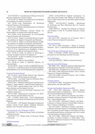
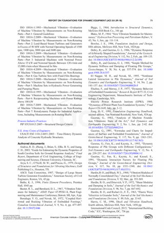
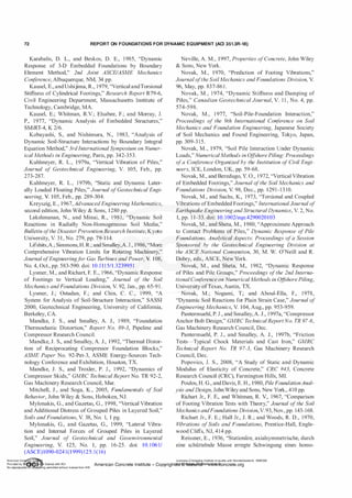


![Unit-2 [Dynamic Equipment Foundation].pdf](https://cdn.slidesharecdn.com/ss_thumbnails/unit-2dynamicequipmentfoundation-231010072957-6de83d97-thumbnail.jpg?width=640&height=640&fit=bounds)


