Downloaded 13 times
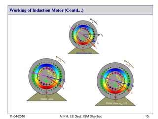
![Working of Induction Motor
11-04-2016 A. Pal, EE Dept., ISM Dhanbad 8
a Fc
-93 10 113 216
-1.5
-1
-0.5
0
0.5
1
1.5
a’
c’
b’
b c
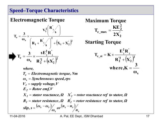
a
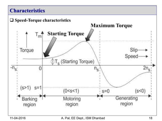
a’
c’ b’
b
c
a
a’
c’
b’
b c
a
a’
c’
b’
b c
Fb
Fb
FcFb
Fc Fc Fb
Space angle () in degrees
Fc
Fb
t = t0= t4
t = t1
t = t2 t = t3
t = t0= t4
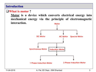
RMF (Rotating Magnetic Field) [video link]](https://image.slidesharecdn.com/imabhisekpal-160411053406/85/Induction-Motor-8-320.jpg)
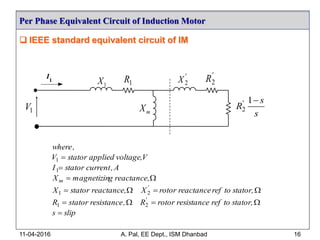
![Working of Induction Motor
11-04-2016 A. Pal, EE Dept., ISM Dhanbad 9
RMF (Rotating Magnetic Field) [video link]](https://image.slidesharecdn.com/imabhisekpal-160411053406/85/Induction-Motor-9-320.jpg)
![Reference
[1] M. G. Say, Alternating current machines, Pitman, 4th Ed., 1976.
[2] D. P. Kothari and I. J. Nagrath, Electric machines, Tata McGraw Hill, 2010.
[3] P. S. Bimbhra, Electrical machinery, Kaanna Publishers, 2010.
[4] B. K. Bose, Modern power electronics and ac drives, Prentice Hall, 2002.
[5] Electrical4u.com, ‘Electrical Engineering and Technology’, 2016. [Online].
Available: http://www.electrical4u.com/working-principle-of-three-phase-
induction-motor. [Accessed: 15- March- 2016].
11-04-2016 A. Pal, EE Dept., ISM Dhanbad 39](https://image.slidesharecdn.com/imabhisekpal-160411053406/85/Induction-Motor-39-320.jpg)
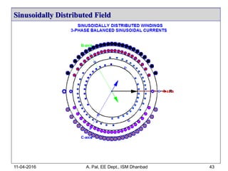
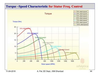
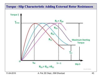
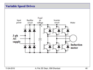
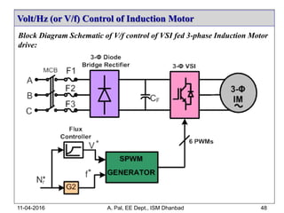
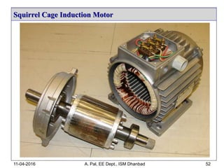
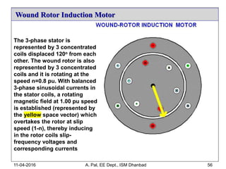
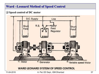

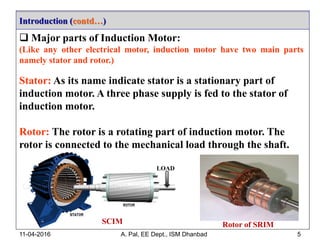
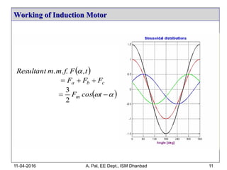
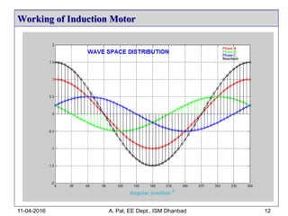
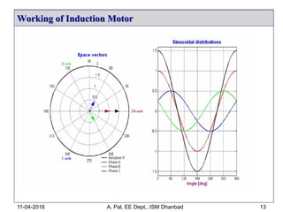
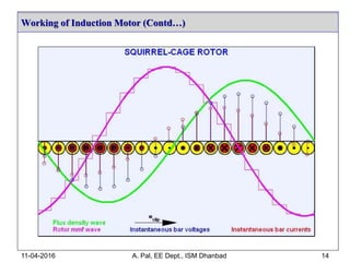
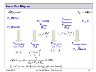
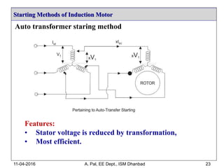
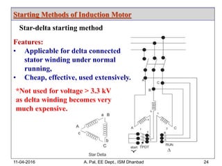
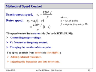
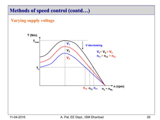
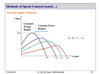
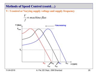
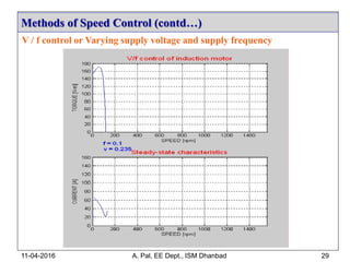
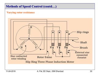
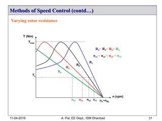
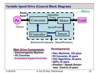
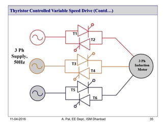
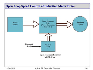
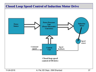
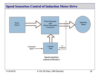
This document provides an overview of induction motors, including their working principles, characteristics, starting methods, speed control methods, and applications in variable speed drives. Some key points: - Induction motors are widely used in industry due to their ruggedness, low cost, and high efficiency. They make up around 80% of all electric motors. - The motor consists of a stationary stator and a rotating rotor. Depending on the rotor type, induction motors are classified as squirrel cage or slip ring motors. - A rotating magnetic field is produced in the stator by a three-phase supply. This induces currents in the rotor and generates torque. Speed is controlled by varying supply voltage, frequency, or rotor


