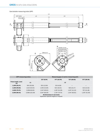
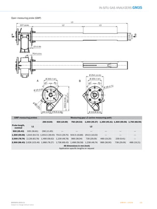
PRODUCTINFORMATION
GM35
IN-SITU IR GAS ANALYZER
SIMULTANEOUS OR INDIVIDUAL MEASUREMENT OF
CO2
, H2
O AND CO OR N2
O
In-situ gas analyzer
G M 3 5 | S I C K 8009253/2015-11
Subject to change without notice
22
GM35 In-situ Gas analyzer
Simple and cost-saving
With the innovative in-situ measurement technology, SICK
provides equipment solutions mainly characterized by simple
installation and start-up, minimum maintenance and extremely
short response times. This is because the GM35 measures
the sample gases, including pressure and temperature in-situ,
i.e. directly in the gas carrying duct. Moreover, this is achieved
quickly and without complicated gas sampling or transporta-
tion, therefore avoiding the risk of changing or falsifying the
gas composition.
The GM35 has a compact sender/receiver unit with zero point
reflector, gas cell and grid filter which enable a real zero point
and span test (QAL3). Complicated adjustment with test gases
is not required.
Proven measurement technology
In-situ gas analyzer GM35 contains optical and electronic
subassemblies for simultaneous or individual measurement of
gas components CO2
, H2
O and CO or N2
O. The in-situ measure-
ment technology allows direct installation of the analyzer at
the respective measuring location.
Two versions are available:
•	 A cross-duct version for representative measured results
across the entire duct cross diameter.
•	 A measuring probe version – optimized for single-sided
installation allowing simple integration into an extremely
varied range of system conditions.
Efficient control of combustion and drying processes
Efficient control of process-relevant parameters is important for controlling and regulating
combustion or drying processes. Apart from oxygen, mainly CO must be reliably and exactly
measured. In drying processes, the humidity curve during the process must be acquired and the
plants monitored for CO concentrations. The in-situ gas analyzer GM35 from SICK is predestined
for this purpose because it measures CO, CO2
and H2
O simultaneously and directly in the process.
Moreover, monitoring and reducing greenhouse gas emissions in industrial plants is becoming
more and more important. The GM35 measures the concentrations of greenhouse gases CO2
and
N2
O as well as CO also in this sector and measures fast or short-time process fluctuations with
excellent precision.
G M 3 5 | S I C K8009253/2015-11
Subject to change without notice
33
In-situ Gas analyzer GM35
GMP measuring probe
•	 Single-side duct access and simple
installation
•	 Integrated zero point path
•	 Application adaptation, independent
from duct dimensions
•	 Versatile use, suitable for dust con-
centrations up to 3 g/m3
•	 Cost-efficient to purchase
GPP gas diffusion probe
•	 Single-side duct access
•	 Suitable for applications with high
dust concentrations
•	 Integrated zero point path
•	 Application adaptation, independent
from duct dimensions
•	 Gas check possible (EPA compliant)
•	 Suitable for turbulent gas flows
Cross Duct version
Measuring probe version
Sender/receiver unit
GPP gas diffusion probe
Open GMP measuring probe
Reflector unit
Additional components
•	 Evaluation unit for measured value
editing, output and control function
•	 Purge air unit for GMP measuring
probe and for Cross-Duct version
•	 Optional components:
•	 Flange with tube, weather
protection
•	 Probe with temperature and pres-
sure sensor for Cross-Duct layout
•	 System Control Unit SCU
Sender/receiver unit with measuring
probe. Two measuring probe types with
integrated temperature and pressure
sensors are available:
•	 GMP measuring probe with open
measuring path
•	 GPP gas diffusion probe
Sender/receiver unit and reflector unit
are installed opposite each other at
the measuring location.
•	 Representative
measuring results
over the whole duct
cross-sections;
also over large duct
diameters
•	 Requires very little
maintenance
•	 Very fast reaction
time
G M 3 5 | S I C K 8009253/2015-11
Subject to change without notice
44
GM35 In-situ gas analyzers
Product description
Simultaneous or individual measure­
ments: the GM35 gas analyzer mea-
sures CO2
, H2
O and CO or N2
concen-
trations as well as temperature and
pressure quickly, easily and economi-
cally. The in-situ measurement technol-
ogy of the GM35 records the measured
values directly in the gas-carrying
duct without gas sampling. Reliability,
accuracy and short response time of
the analyzer offer a key advantage for
efficient control loops in all CO and CO2
generating processes.
At a glance
•	 Dynamic humidity correction
•	 Fast in-situ measurement directly in
the process
•	 Simultaneous determination of up to
three gas components, temperature
and pressure
•	 No gas sampling and conditioning
•	 Gas testable version of measuring
probe available
•	 Integrated self test and control
functions
Your benefits
•	 Dynamic humidity measurement
directly in the process
•	 Provision of real humidity reference
values
•	 Unbiased measured values due to
in-situ measurement
•	 Fast or short-term fluctuations in the
process are recorded
•	 Representative measurement by
selection of an appropriate probe or
cross-duct type
EFFICIENT CONTROL OF COMBUSTION AND
DEHYDRATION PROCESSES
Additional information
Fields of application����������������������������5
Detailed technical data������������������������5
Ordering information����������������������������9
Dimensional drawings��������������������������9
15267
certified
14181
certified
-- www.mysick.com/en/GM35
For more information, just enter the link and get direct access to technical data, CAD design models, operating
instructions, software, application examples and much more.
G M 3 5 | S I C K8009253/2015-11
Subject to change without notice
55
In-situ gas analyzers GM35
Fields of application
•	 Emission monitoring according to EN 14181, e.g.
in power or cement plants
•	 Control of the water-injection upstream of the
electrostatic precipitator
•	 Monitoring of combustion efficiency in hazardous
waste incineration
•	 Process monitoring in urea production
•	 Tube rupture detection in heat exchangers
Detailed technical data
The exact device specifications and performance data of the product may deviate from the information provided here, and depend on the
application in which the product is being used and the relevant customer specifications.
GM35 system
Measured values CO, CO2
, H2
O, N2
O
Performance tested measurands CO, CO2
, H2
O
Measurement principles Gas filter correlation, Interference filter correlation
Measuring ranges
CO 0 ... 180 ppm / 0 ... 20,000 ppm
CO2
0 ... 22.5 Vol.-% / 0 ... 100 Vol.-%
H2
O 0 ... 25 Vol.-% / 0 ... 100 Vol.-%
N2
O 0 ... 60 ppm / 0 ... 2,500 ppm
Measuring ranges refer to 1 m measuring path
Measuring ranges depend on application and device version
Certified measuring ranges
CO 0 ... 75 mg/m³ / 0 ... 2,000 mg/m³
CO2
0 ... 15 Vol.-%
H2
O 0 ... 25 Vol.-%
Cross-duct and GMP version are type approved
Zero point drift ± 2 % relative to measuring range end value
Reference point drift ± 2 % within the maintenance interval, relative to measuring range full scale
Ambient temperature –40 °C ... +55 °C
Temperature change ±10 °C/h maximum
Storage temperature –40 °C ... +55 °C
Ambient humidity ≤ 96 %
Relative humidity; bedewing of optical surfaces not permitted
Conformities EN 14181
EN 15267
2001/80/EC
2000/76/EC
27. BImSchV
Electrical safety CE
Enclosure rating IP 65 / NEMA 4x
Operation Menu-driven operation via separate control unit
Model Cross-duct version
Measuring probe version
Test functions Automatic control cycle for zero and span point
G M 3 5 | S I C K 8009253/2015-11
Subject to change without notice
66
GM35 In-situ gas analyzers
Sender/receiver unit
Description Analyzer unit of the measuring system
Enclosure rating IP 65 / NEMA 4x
Bus protocol CAN (internal system bus)
Dimensions (W x H x D) 291 mm x 527 mm x 529 mm
Weight ≤ ± 29 kg
Electrical connection
Voltage 115 V AC / 230 V AC
Frequency 48 ... 62 Hz
Power consumption ≤ 350 W
Open measuring probe (GMP)
Description Measuring probe in open design with integrated purge air control system
Process temperature ≤ +430 °C
For N2
O measurement max 180 °C
Process pressure ≤ 120 hPa
Depending on purge air supply
Process gas velocity ≤ 40 m/s
Dust load ≤ 3 g/m³
Bus protocol CAN (internal system bus)
Dimensions (W x H x D) See dimensional drawings
Weight Measuring probe: ≤ ± 25 kg
Purge air fixture: ≤ ± 7 kg
Material in contact with media Stainless steel 1.4571, stainless steel 1.4539
Auxiliary connections Purge air
Integrated components Pressure sensor
PT1000 temperature sensor
Gas-testable measuring probe (GPP)
Description Measuring probe with gas permeable filter element for adjustment with test gas
Process temperature ≤ +430 °C
For N2
O measurement max 180 °C
Process pressure ≤ 250 hPa
Depending on purge air supply
Process gas velocity ≤ 40 m/s
Dust load ≤ 30 g/m³
Bus protocol CAN (internal system bus)
Dimensions (W x H x D) See dimensional drawings
Weight Measuring probe: ≤ ± 45 kg
Purge air fixture: ≤ ± 7 kg
Material in contact with media Stainless steel 1.4571, stainless steel 1.4539, ceramics, PTFE
Electrical connection
Voltage 115 V AC / 230 V AC
Frequency 50 Hz / 60 Hz
Power consumption ≤ 150 W
Auxiliary connections Test gas
Purge air
Integrated components Pressure sensor
PT1000 temperature sensor
G M 3 5 | S I C K8009253/2015-11
Subject to change without notice
77
In-situ gas analyzers GM35
Reflector unit
Description Reflector unit with hollow triple reflector
Process temperature ≤ +500 °C
For N2
O measurement max 180 °C
Process pressure Depending on purge air supply
Dimensions (W x H x D) 291 mm x 280 mm x 161 mm
Weight ≤ ± 1.5 kg
GM35 evaluation unit: steel sheet enclosure
Description The evaluation unit serves as user interface and is responsible for data processing and out-
put as well as control and monitoring functions
Enclosure rating IP 65 / NEMA 4x
Analog outputs 3 outputs:
0/4 ... 20 mA, 500 Ω
Electrically isolated
Analog inputs 1 input:
0 ... 20 mA, 100 Ω
Digital outputs 3 relay contacts:
48 V AC, 1 A, 60 W / 48 V DC, 1 A, 30 W
Digital inputs 3 inputs:
24 V
Preset for failure, maintenance and functional control
Interfaces RS-232 (service interface)
Bus protocol CAN (internal system bus)
Indication LC display
Status LEDs: “Power”, “Maintenance” and “Fault”
Input Arrow keys
Functional keys
Operation Menu-driven operation via LC-display and membrane keyboard
Model Steel sheet enclosure
Dimensions (W x H x D) 200 mm x 346 mm x 97.5 mm
Weight ≤ ± 3 kg
Electrical connection
Voltage 115 V / 230 V
Frequency 50 Hz / 60 Hz
Power consumption ≤ 50 W
GM35 evaluation unit: cast metal enclosure
Description The evaluation unit serves as user interface and is responsible for data processing and out-
put as well as control and monitoring functions
Enclosure rating IP 67
Analog outputs 3 outputs:
0/4 ... 20 mA, 500 Ω
Electrically isolated
Analog inputs 1 input:
0 ... 20 mA, 100 Ω
Digital outputs 3 relay contacts:
48 V AC, 1 A, 60 W / 48 V DC, 1 A, 30 W
Preset for failure, maintenance and functional control
Digital inputs 3 inputs:
24 V
Interfaces RS-232 (service interface)
G M 3 5 | S I C K 8009253/2015-11
Subject to change without notice
88
GM35 In-situ gas analyzers
Bus protocol CAN (internal system bus)
Indication LC display
Status LEDs: “Power”, “Maintenance” and “Fault”
Input Arrow keys
Functional keys
Operation Menu-driven operation via LC-display and membrane keyboard
Model Cast metal enclosure
Dimensions (W x H x D) 289 mm x 370 mm x 138 mm
Weight ≤ ± 3 kg
Electrical connection
Voltage 115 V / 230 V
Frequency 50 Hz / 60 Hz
Power consumption ≤ 50 W
Connection unit
Description To lengthen the internal CAN-Bus connection with cable provided by the customer
Bus protocol CAN (internal system bus)
Dimensions (W x H x D) 125 mm x 103 mm x 57 mm
Weight ≤ ± 3 kg
Purge air fixture: sender/receiver unit
Description Fixture to flanges with connections for purge air and external cabelling
Bus protocol CAN (internal system bus)
Dimensions (W x H x D) 320.9 mm x 360 mm x 220 mm
Weight ≤ ± 7 kg
Auxiliary connections Purge air
Integrated components PT1000 temperature sensor
Pressure sensor
Purge air fixture: reflector unit
Description Fixture to flanges with connections for purge air and external cabelling
Bus protocol CAN (internal system bus)
Dimensions (W x H x D) 320.9 mm x 360 mm x 220 mm
Weight ≤ ± 7 kg
Auxiliary connections Purge air
G M 3 5 | S I C K8009253/2015-11
Subject to change without notice
99
In-situ gas analyzers GM35
Ordering information
Our regional sales organization will help you to select the optimum device configuration.
Dimensional drawings (Dimensions in mm (inch))
GM35 sender/receiver unit
291 (11.46)
135 (5.31) 156 (6.14)
45° 45°
99,7
(3,93)
531,7 (20.93)
6,8
(0.27)
200(7.87)
27
(1.06)
110(4.33)390(15.35)106
(4.17)
643(25.31)

95°
G M 3 5 | S I C K 8009253/2015-11
Subject to change without notice
1 01 0
GM35 In-situ gas analyzers
Gas-testable measuring probe (GPP)
Ø 254 (10.00)
Ø 215.8 (8.50)
Ø 22.4 (0.88)
45°
Ø 18 (0.71)45°
Ø 200 (7.87)
B
A
238 (9.37)
360(14.17)
233(9.17)
Ø254
(10.00)
Ø114.3
(4.50)
L2
L1
L3
B
10 (0.39)
227 (8.94)
A
GPP measuring probes Measuring gap L3 (active measuring path)
227 (8.94) 477 (18.78) 727 (28.62) 977 (38.46)
Probe length, nomi-
nal
L1 L2
1,000 (39.37) 904 (35.59) 353 (13.90) 103 (4.06) --- ---
1,500 (59.06) 1,614 (63.54) 1,063 (41.85) 813 (32.01) 563 (22.17) 313 (12.32)
2,000 (78.74) 2,098 (82.60) 1,547 (60.91) 1,297 (51.06) 1,047 (41.22) 797 (31.38)
2,500 (98.43) 2,598 (102.28) 2,047 (80.59) 1,797 (70.75) 1,547 (60.91) 1,297 (51.06)
All dimensions in mm (inch)
Application specific lengths on request
G M 3 5 | S I C K8009253/2015-11
Subject to change without notice
1 11 1
In-situ gas analyzers GM35
Open measuring probe (GMP)
Ø 200 (7.87)
Ø
40
(1.57)
Ø 14 (0.55)
360(14.17)
233.2(9.18)
176.9 (6.98)144 (5.67)
45° 45°
Ø 254 (10.00)
Ø 200 (7.87)
Ø 18 (0.71)
Ø 215.8 (8.50)
45° 45°
L1
L2 L3
Ø114.3
(4.50)
10 (0.39)
227 (8.94)
55
(2.17)
76.4 (3.01)
BA
BA
GMP measuring probes Measuring gap L3 (active measuring path)
250 (9.84) 500 (19.69) 750 (29.53) 1,000 (39.37) 1,250 (49.21) 1,500 (59.06) 1,750 (68.90)
Probe length,
nominal
L1 L2 
900 (35.43) 935 (36.81) 296 (11.65) --- --- --- --- --- ---
1,500 (59.06) 1,644 (64.72) 1,004.5 (39.55) 754.5 (29.70) 504.5 (19.86) 254.5 (10.02) --- --- ---
2,000 (78.74) 2,128 (83.78) 1,489 (58.62) 1,239 (48.78) 989 (38.94) 739 (29.09) 489 (19.25) 239 (9.41) ---
2,500 (98.43) 2,628 (103.46) 1,988 (78.27) 1,738 (68.43) 1,488 (58.58) 1,238 (48.74) 988 (38.90) 738 (29.06) 488 (19.21)
All dimensions in mm (inch)
Application specific lengths on request
G M 3 5 | S I C K 8009253/2015-11
Subject to change without notice
1 21 2
GM35 In-situ gas analyzers
GM35 reflector unit
161 (6.34)
280(11.02)
146 (5.75)
135 (5.31)
291 (11.46)
Ø 200
(7.87)
45°
144(5.67)
35.5
(1.40)
45°
R = 295(11.61)
Max. 120°
GM35 AWE evaluation unit: steel sheet enclosure
23
(0.91)
97.5(3.84)
90 (3.54)
82 (3.22)
322(12.68)
300(11.81)
160 (6.30)
200 (7.87)
Ø 8 (0.31)
G M 3 5 | S I C K8009253/2015-11
Subject to change without notice
1 31 3
In-situ gas analyzers GM35
GM35 AWE evaluation unit: cast metal enclosure
260 (10.24)
289 (11.38)
R = 273 (10.75)
25(0.98)
370(14.57)
138(5.43)
85(3.35)
330(12.99)
235 (9.25)
Ø 7 (0.28)
GM35 connection unit
Ø 5
(0.20)
PG11
PG13,5
52(2.05)
113 (4.45)6 (0.24)
125 (4.92)
14
(0.55)
80(3.15)23
(0.91)
57(2.24)
G M 3 5 | S I C K 8009253/2015-11
Subject to change without notice
1 41 4
GM35 In-situ gas analyzers
Mounting flange, Di
=125 mm
Ø240(9.45)
Ø178(7.01)
Ø125(4.92)
Ø133(5.24)
8 (0.31)
14 (0.55)
240 / 500 / 1,000
(9.45 / 19.69 / 39.37)
3.6–4.0
(.14–.16)
3 (0.12)
45°
Ø 200 (7.87)
Ø 18 (0.71)
Weather hood for reflector unit
300(11.81)
321(12.64)
27(1.06)
248 (9.76)
325 (12.80)
309(12.17)
180 (7.09)
169 (6.65)
320(12.60)
Weather hood for sender/receiver unit
636.4 (25.06)
576.3 (22.69)
525.8 (20.7) 25.2
(0.99)
507.8(19.99)
297(11.69)
Ø
240
(9.45)
G M 3 5 | S I C K8009253/2015-11
Subject to change without notice
1 5
SERVICES FOR MACHINES AND SYSTEMS: SICK LifeTime Services
Our comprehensive and versatile LifeTime Services are the perfect addition to the comprehensive range of products from
SICK. The services range from product-independent consulting to traditional product services.
Training and education
Practical, focused and professional
Upgrade and retrofits
Easy, safe and economical
Consulting and design
Safe and professional
Verification and optimization
Safe and regularly inspected
Product and system support
Reliable, fast and on-site
SERVICES
REGISTER AT WWW.SICK.COM TODAY AND
ENJOY ALL THE BENEFITS
Select products, accessories, documentation and soft-
ware quickly and easily.
Create, save and share personalized wish lists.
View the net price and date of delivery for every product.
Requests for quotation, ordering and delivery tracking
made easy.
Overview of all quotations and orders.
Direct ordering: submit even very complex orders in
moments.
View the status of quotations and orders at any time.
Receive e-mail notifications of status changes. 
Easily repeat previous orders.
Conveniently export quotations and orders to work with
your systems.
m
m
m
m
m
m
m
m
m
SICK AG	 |	Waldkirch	|	Germany	|	www.sick.com
SICK AT A GLANCE
SICK is a leading manufacturer of intelligent sensors and sensor solutions for industrial applications. With
almost 7,000 employees and over 50 subsidiaries and equity investments as well as numerous represen-
tative offices worldwide, we are always close to our customers. A unique range of products and services
creates the perfect basis for controlling processes securely and efficiently, protecting individuals from ac-
cidents and preventing damage to the environment.
We have extensive experience in various industries and understand their processes and requirements.
With intelligent sensors, we can deliver exactly what our customers need. In application centers in Europe,
Asia and North America, system solutions are tested and optimized in accordance with customer specifica-
tions. All this makes us a reliable supplier and development partner.
Comprehensive services round out our offering: SICK LifeTime Services provide support throughout the
machine life cycle and ensure safety and productivity.
For us, that is “Sensor Intelligence.”
Worldwide presence:
Australia, Austria, Belgium, Brazil, Canada, Chile, China, Czech Republic, Denmark, Finland, France,
Germany, Great Britain, Hungary, India, Israel, Italy, Japan, Malaysia, Mexico, Netherlands, New Zealand,
Norway, Poland, Romania, Russia, Singapore, Slovakia, Slovenia, South Africa, South Korea, Spain,
Sweden, Switzerland, Taiwan, Thailand, Turkey, United Arab Emirates, USA, Vietnam.
Detailed addresses and additional representatives - www.sick.com
8009253/2015-11∙3PMS∙PreUSmoden44

In Situ Infrared Gas Analyzer

  • 1.
    PRODUCTINFORMATION GM35 IN-SITU IR GASANALYZER SIMULTANEOUS OR INDIVIDUAL MEASUREMENT OF CO2 , H2 O AND CO OR N2 O In-situ gas analyzer
  • 2.
    G M 35 | S I C K 8009253/2015-11 Subject to change without notice 22 GM35 In-situ Gas analyzer Simple and cost-saving With the innovative in-situ measurement technology, SICK provides equipment solutions mainly characterized by simple installation and start-up, minimum maintenance and extremely short response times. This is because the GM35 measures the sample gases, including pressure and temperature in-situ, i.e. directly in the gas carrying duct. Moreover, this is achieved quickly and without complicated gas sampling or transporta- tion, therefore avoiding the risk of changing or falsifying the gas composition. The GM35 has a compact sender/receiver unit with zero point reflector, gas cell and grid filter which enable a real zero point and span test (QAL3). Complicated adjustment with test gases is not required. Proven measurement technology In-situ gas analyzer GM35 contains optical and electronic subassemblies for simultaneous or individual measurement of gas components CO2 , H2 O and CO or N2 O. The in-situ measure- ment technology allows direct installation of the analyzer at the respective measuring location. Two versions are available: • A cross-duct version for representative measured results across the entire duct cross diameter. • A measuring probe version – optimized for single-sided installation allowing simple integration into an extremely varied range of system conditions. Efficient control of combustion and drying processes Efficient control of process-relevant parameters is important for controlling and regulating combustion or drying processes. Apart from oxygen, mainly CO must be reliably and exactly measured. In drying processes, the humidity curve during the process must be acquired and the plants monitored for CO concentrations. The in-situ gas analyzer GM35 from SICK is predestined for this purpose because it measures CO, CO2 and H2 O simultaneously and directly in the process. Moreover, monitoring and reducing greenhouse gas emissions in industrial plants is becoming more and more important. The GM35 measures the concentrations of greenhouse gases CO2 and N2 O as well as CO also in this sector and measures fast or short-time process fluctuations with excellent precision.
  • 3.
    G M 35 | S I C K8009253/2015-11 Subject to change without notice 33 In-situ Gas analyzer GM35 GMP measuring probe • Single-side duct access and simple installation • Integrated zero point path • Application adaptation, independent from duct dimensions • Versatile use, suitable for dust con- centrations up to 3 g/m3 • Cost-efficient to purchase GPP gas diffusion probe • Single-side duct access • Suitable for applications with high dust concentrations • Integrated zero point path • Application adaptation, independent from duct dimensions • Gas check possible (EPA compliant) • Suitable for turbulent gas flows Cross Duct version Measuring probe version Sender/receiver unit Sender/receiver unit GPP gas diffusion probe Open GMP measuring probe Reflector unit Additional components • Evaluation unit for measured value editing, output and control function • Purge air unit for GMP measuring probe and for Cross-Duct version • Optional components: • Flange with tube, weather protection • Probe with temperature and pres- sure sensor for Cross-Duct layout • System Control Unit SCU Sender/receiver unit with measuring probe. Two measuring probe types with integrated temperature and pressure sensors are available: • GMP measuring probe with open measuring path • GPP gas diffusion probe Sender/receiver unit and reflector unit are installed opposite each other at the measuring location. • Representative measuring results over the whole duct cross-sections; also over large duct diameters • Requires very little maintenance • Very fast reaction time
  • 4.
    G M 35 | S I C K 8009253/2015-11 Subject to change without notice 44 GM35 In-situ gas analyzers Product description Simultaneous or individual measure­ ments: the GM35 gas analyzer mea- sures CO2 , H2 O and CO or N2 concen- trations as well as temperature and pressure quickly, easily and economi- cally. The in-situ measurement technol- ogy of the GM35 records the measured values directly in the gas-carrying duct without gas sampling. Reliability, accuracy and short response time of the analyzer offer a key advantage for efficient control loops in all CO and CO2 generating processes. At a glance • Dynamic humidity correction • Fast in-situ measurement directly in the process • Simultaneous determination of up to three gas components, temperature and pressure • No gas sampling and conditioning • Gas testable version of measuring probe available • Integrated self test and control functions Your benefits • Dynamic humidity measurement directly in the process • Provision of real humidity reference values • Unbiased measured values due to in-situ measurement • Fast or short-term fluctuations in the process are recorded • Representative measurement by selection of an appropriate probe or cross-duct type EFFICIENT CONTROL OF COMBUSTION AND DEHYDRATION PROCESSES Additional information Fields of application����������������������������5 Detailed technical data������������������������5 Ordering information����������������������������9 Dimensional drawings��������������������������9 15267 certified 14181 certified -- www.mysick.com/en/GM35 For more information, just enter the link and get direct access to technical data, CAD design models, operating instructions, software, application examples and much more.
  • 5.
    G M 35 | S I C K8009253/2015-11 Subject to change without notice 55 In-situ gas analyzers GM35 Fields of application • Emission monitoring according to EN 14181, e.g. in power or cement plants • Control of the water-injection upstream of the electrostatic precipitator • Monitoring of combustion efficiency in hazardous waste incineration • Process monitoring in urea production • Tube rupture detection in heat exchangers Detailed technical data The exact device specifications and performance data of the product may deviate from the information provided here, and depend on the application in which the product is being used and the relevant customer specifications. GM35 system Measured values CO, CO2 , H2 O, N2 O Performance tested measurands CO, CO2 , H2 O Measurement principles Gas filter correlation, Interference filter correlation Measuring ranges CO 0 ... 180 ppm / 0 ... 20,000 ppm CO2 0 ... 22.5 Vol.-% / 0 ... 100 Vol.-% H2 O 0 ... 25 Vol.-% / 0 ... 100 Vol.-% N2 O 0 ... 60 ppm / 0 ... 2,500 ppm Measuring ranges refer to 1 m measuring path Measuring ranges depend on application and device version Certified measuring ranges CO 0 ... 75 mg/m³ / 0 ... 2,000 mg/m³ CO2 0 ... 15 Vol.-% H2 O 0 ... 25 Vol.-% Cross-duct and GMP version are type approved Zero point drift ± 2 % relative to measuring range end value Reference point drift ± 2 % within the maintenance interval, relative to measuring range full scale Ambient temperature –40 °C ... +55 °C Temperature change ±10 °C/h maximum Storage temperature –40 °C ... +55 °C Ambient humidity ≤ 96 % Relative humidity; bedewing of optical surfaces not permitted Conformities EN 14181 EN 15267 2001/80/EC 2000/76/EC 27. BImSchV Electrical safety CE Enclosure rating IP 65 / NEMA 4x Operation Menu-driven operation via separate control unit Model Cross-duct version Measuring probe version Test functions Automatic control cycle for zero and span point
  • 6.
    G M 35 | S I C K 8009253/2015-11 Subject to change without notice 66 GM35 In-situ gas analyzers Sender/receiver unit Description Analyzer unit of the measuring system Enclosure rating IP 65 / NEMA 4x Bus protocol CAN (internal system bus) Dimensions (W x H x D) 291 mm x 527 mm x 529 mm Weight ≤ ± 29 kg Electrical connection Voltage 115 V AC / 230 V AC Frequency 48 ... 62 Hz Power consumption ≤ 350 W Open measuring probe (GMP) Description Measuring probe in open design with integrated purge air control system Process temperature ≤ +430 °C For N2 O measurement max 180 °C Process pressure ≤ 120 hPa Depending on purge air supply Process gas velocity ≤ 40 m/s Dust load ≤ 3 g/m³ Bus protocol CAN (internal system bus) Dimensions (W x H x D) See dimensional drawings Weight Measuring probe: ≤ ± 25 kg Purge air fixture: ≤ ± 7 kg Material in contact with media Stainless steel 1.4571, stainless steel 1.4539 Auxiliary connections Purge air Integrated components Pressure sensor PT1000 temperature sensor Gas-testable measuring probe (GPP) Description Measuring probe with gas permeable filter element for adjustment with test gas Process temperature ≤ +430 °C For N2 O measurement max 180 °C Process pressure ≤ 250 hPa Depending on purge air supply Process gas velocity ≤ 40 m/s Dust load ≤ 30 g/m³ Bus protocol CAN (internal system bus) Dimensions (W x H x D) See dimensional drawings Weight Measuring probe: ≤ ± 45 kg Purge air fixture: ≤ ± 7 kg Material in contact with media Stainless steel 1.4571, stainless steel 1.4539, ceramics, PTFE Electrical connection Voltage 115 V AC / 230 V AC Frequency 50 Hz / 60 Hz Power consumption ≤ 150 W Auxiliary connections Test gas Purge air Integrated components Pressure sensor PT1000 temperature sensor
  • 7.
    G M 35 | S I C K8009253/2015-11 Subject to change without notice 77 In-situ gas analyzers GM35 Reflector unit Description Reflector unit with hollow triple reflector Process temperature ≤ +500 °C For N2 O measurement max 180 °C Process pressure Depending on purge air supply Dimensions (W x H x D) 291 mm x 280 mm x 161 mm Weight ≤ ± 1.5 kg GM35 evaluation unit: steel sheet enclosure Description The evaluation unit serves as user interface and is responsible for data processing and out- put as well as control and monitoring functions Enclosure rating IP 65 / NEMA 4x Analog outputs 3 outputs: 0/4 ... 20 mA, 500 Ω Electrically isolated Analog inputs 1 input: 0 ... 20 mA, 100 Ω Digital outputs 3 relay contacts: 48 V AC, 1 A, 60 W / 48 V DC, 1 A, 30 W Digital inputs 3 inputs: 24 V Preset for failure, maintenance and functional control Interfaces RS-232 (service interface) Bus protocol CAN (internal system bus) Indication LC display Status LEDs: “Power”, “Maintenance” and “Fault” Input Arrow keys Functional keys Operation Menu-driven operation via LC-display and membrane keyboard Model Steel sheet enclosure Dimensions (W x H x D) 200 mm x 346 mm x 97.5 mm Weight ≤ ± 3 kg Electrical connection Voltage 115 V / 230 V Frequency 50 Hz / 60 Hz Power consumption ≤ 50 W GM35 evaluation unit: cast metal enclosure Description The evaluation unit serves as user interface and is responsible for data processing and out- put as well as control and monitoring functions Enclosure rating IP 67 Analog outputs 3 outputs: 0/4 ... 20 mA, 500 Ω Electrically isolated Analog inputs 1 input: 0 ... 20 mA, 100 Ω Digital outputs 3 relay contacts: 48 V AC, 1 A, 60 W / 48 V DC, 1 A, 30 W Preset for failure, maintenance and functional control Digital inputs 3 inputs: 24 V Interfaces RS-232 (service interface)
  • 8.
    G M 35 | S I C K 8009253/2015-11 Subject to change without notice 88 GM35 In-situ gas analyzers Bus protocol CAN (internal system bus) Indication LC display Status LEDs: “Power”, “Maintenance” and “Fault” Input Arrow keys Functional keys Operation Menu-driven operation via LC-display and membrane keyboard Model Cast metal enclosure Dimensions (W x H x D) 289 mm x 370 mm x 138 mm Weight ≤ ± 3 kg Electrical connection Voltage 115 V / 230 V Frequency 50 Hz / 60 Hz Power consumption ≤ 50 W Connection unit Description To lengthen the internal CAN-Bus connection with cable provided by the customer Bus protocol CAN (internal system bus) Dimensions (W x H x D) 125 mm x 103 mm x 57 mm Weight ≤ ± 3 kg Purge air fixture: sender/receiver unit Description Fixture to flanges with connections for purge air and external cabelling Bus protocol CAN (internal system bus) Dimensions (W x H x D) 320.9 mm x 360 mm x 220 mm Weight ≤ ± 7 kg Auxiliary connections Purge air Integrated components PT1000 temperature sensor Pressure sensor Purge air fixture: reflector unit Description Fixture to flanges with connections for purge air and external cabelling Bus protocol CAN (internal system bus) Dimensions (W x H x D) 320.9 mm x 360 mm x 220 mm Weight ≤ ± 7 kg Auxiliary connections Purge air
  • 9.
    G M 35 | S I C K8009253/2015-11 Subject to change without notice 99 In-situ gas analyzers GM35 Ordering information Our regional sales organization will help you to select the optimum device configuration. Dimensional drawings (Dimensions in mm (inch)) GM35 sender/receiver unit 291 (11.46) 135 (5.31) 156 (6.14) 45° 45° 99,7 (3,93) 531,7 (20.93) 6,8 (0.27) 200(7.87) 27 (1.06) 110(4.33)390(15.35)106 (4.17) 643(25.31) 95°
  • 10.
    G M 35 | S I C K 8009253/2015-11 Subject to change without notice 1 01 0 GM35 In-situ gas analyzers Gas-testable measuring probe (GPP) Ø 254 (10.00) Ø 215.8 (8.50) Ø 22.4 (0.88) 45° Ø 18 (0.71)45° Ø 200 (7.87) B A 238 (9.37) 360(14.17) 233(9.17) Ø254 (10.00) Ø114.3 (4.50) L2 L1 L3 B 10 (0.39) 227 (8.94) A GPP measuring probes Measuring gap L3 (active measuring path) 227 (8.94) 477 (18.78) 727 (28.62) 977 (38.46) Probe length, nomi- nal L1 L2 1,000 (39.37) 904 (35.59) 353 (13.90) 103 (4.06) --- --- 1,500 (59.06) 1,614 (63.54) 1,063 (41.85) 813 (32.01) 563 (22.17) 313 (12.32) 2,000 (78.74) 2,098 (82.60) 1,547 (60.91) 1,297 (51.06) 1,047 (41.22) 797 (31.38) 2,500 (98.43) 2,598 (102.28) 2,047 (80.59) 1,797 (70.75) 1,547 (60.91) 1,297 (51.06) All dimensions in mm (inch) Application specific lengths on request
  • 11.
    G M 35 | S I C K8009253/2015-11 Subject to change without notice 1 11 1 In-situ gas analyzers GM35 Open measuring probe (GMP) Ø 200 (7.87) Ø 40 (1.57) Ø 14 (0.55) 360(14.17) 233.2(9.18) 176.9 (6.98)144 (5.67) 45° 45° Ø 254 (10.00) Ø 200 (7.87) Ø 18 (0.71) Ø 215.8 (8.50) 45° 45° L1 L2 L3 Ø114.3 (4.50) 10 (0.39) 227 (8.94) 55 (2.17) 76.4 (3.01) BA BA GMP measuring probes Measuring gap L3 (active measuring path) 250 (9.84) 500 (19.69) 750 (29.53) 1,000 (39.37) 1,250 (49.21) 1,500 (59.06) 1,750 (68.90) Probe length, nominal L1 L2  900 (35.43) 935 (36.81) 296 (11.65) --- --- --- --- --- --- 1,500 (59.06) 1,644 (64.72) 1,004.5 (39.55) 754.5 (29.70) 504.5 (19.86) 254.5 (10.02) --- --- --- 2,000 (78.74) 2,128 (83.78) 1,489 (58.62) 1,239 (48.78) 989 (38.94) 739 (29.09) 489 (19.25) 239 (9.41) --- 2,500 (98.43) 2,628 (103.46) 1,988 (78.27) 1,738 (68.43) 1,488 (58.58) 1,238 (48.74) 988 (38.90) 738 (29.06) 488 (19.21) All dimensions in mm (inch) Application specific lengths on request
  • 12.
    G M 35 | S I C K 8009253/2015-11 Subject to change without notice 1 21 2 GM35 In-situ gas analyzers GM35 reflector unit 161 (6.34) 280(11.02) 146 (5.75) 135 (5.31) 291 (11.46) Ø 200 (7.87) 45° 144(5.67) 35.5 (1.40) 45° R = 295(11.61) Max. 120° GM35 AWE evaluation unit: steel sheet enclosure 23 (0.91) 97.5(3.84) 90 (3.54) 82 (3.22) 322(12.68) 300(11.81) 160 (6.30) 200 (7.87) Ø 8 (0.31)
  • 13.
    G M 35 | S I C K8009253/2015-11 Subject to change without notice 1 31 3 In-situ gas analyzers GM35 GM35 AWE evaluation unit: cast metal enclosure 260 (10.24) 289 (11.38) R = 273 (10.75) 25(0.98) 370(14.57) 138(5.43) 85(3.35) 330(12.99) 235 (9.25) Ø 7 (0.28) GM35 connection unit Ø 5 (0.20) PG11 PG13,5 52(2.05) 113 (4.45)6 (0.24) 125 (4.92) 14 (0.55) 80(3.15)23 (0.91) 57(2.24)
  • 14.
    G M 35 | S I C K 8009253/2015-11 Subject to change without notice 1 41 4 GM35 In-situ gas analyzers Mounting flange, Di =125 mm Ø240(9.45) Ø178(7.01) Ø125(4.92) Ø133(5.24) 8 (0.31) 14 (0.55) 240 / 500 / 1,000 (9.45 / 19.69 / 39.37) 3.6–4.0 (.14–.16) 3 (0.12) 45° Ø 200 (7.87) Ø 18 (0.71) Weather hood for reflector unit 300(11.81) 321(12.64) 27(1.06) 248 (9.76) 325 (12.80) 309(12.17) 180 (7.09) 169 (6.65) 320(12.60) Weather hood for sender/receiver unit 636.4 (25.06) 576.3 (22.69) 525.8 (20.7) 25.2 (0.99) 507.8(19.99) 297(11.69) Ø 240 (9.45)
  • 15.
    G M 35 | S I C K8009253/2015-11 Subject to change without notice 1 5 SERVICES FOR MACHINES AND SYSTEMS: SICK LifeTime Services Our comprehensive and versatile LifeTime Services are the perfect addition to the comprehensive range of products from SICK. The services range from product-independent consulting to traditional product services. Training and education Practical, focused and professional Upgrade and retrofits Easy, safe and economical Consulting and design Safe and professional Verification and optimization Safe and regularly inspected Product and system support Reliable, fast and on-site SERVICES REGISTER AT WWW.SICK.COM TODAY AND ENJOY ALL THE BENEFITS Select products, accessories, documentation and soft- ware quickly and easily. Create, save and share personalized wish lists. View the net price and date of delivery for every product. Requests for quotation, ordering and delivery tracking made easy. Overview of all quotations and orders. Direct ordering: submit even very complex orders in moments. View the status of quotations and orders at any time. Receive e-mail notifications of status changes.  Easily repeat previous orders. Conveniently export quotations and orders to work with your systems. m m m m m m m m m
  • 16.
    SICK AG | Waldkirch | Germany | www.sick.com SICKAT A GLANCE SICK is a leading manufacturer of intelligent sensors and sensor solutions for industrial applications. With almost 7,000 employees and over 50 subsidiaries and equity investments as well as numerous represen- tative offices worldwide, we are always close to our customers. A unique range of products and services creates the perfect basis for controlling processes securely and efficiently, protecting individuals from ac- cidents and preventing damage to the environment. We have extensive experience in various industries and understand their processes and requirements. With intelligent sensors, we can deliver exactly what our customers need. In application centers in Europe, Asia and North America, system solutions are tested and optimized in accordance with customer specifica- tions. All this makes us a reliable supplier and development partner. Comprehensive services round out our offering: SICK LifeTime Services provide support throughout the machine life cycle and ensure safety and productivity. For us, that is “Sensor Intelligence.” Worldwide presence: Australia, Austria, Belgium, Brazil, Canada, Chile, China, Czech Republic, Denmark, Finland, France, Germany, Great Britain, Hungary, India, Israel, Italy, Japan, Malaysia, Mexico, Netherlands, New Zealand, Norway, Poland, Romania, Russia, Singapore, Slovakia, Slovenia, South Africa, South Korea, Spain, Sweden, Switzerland, Taiwan, Thailand, Turkey, United Arab Emirates, USA, Vietnam. Detailed addresses and additional representatives - www.sick.com 8009253/2015-11∙3PMS∙PreUSmoden44