Download to read offline
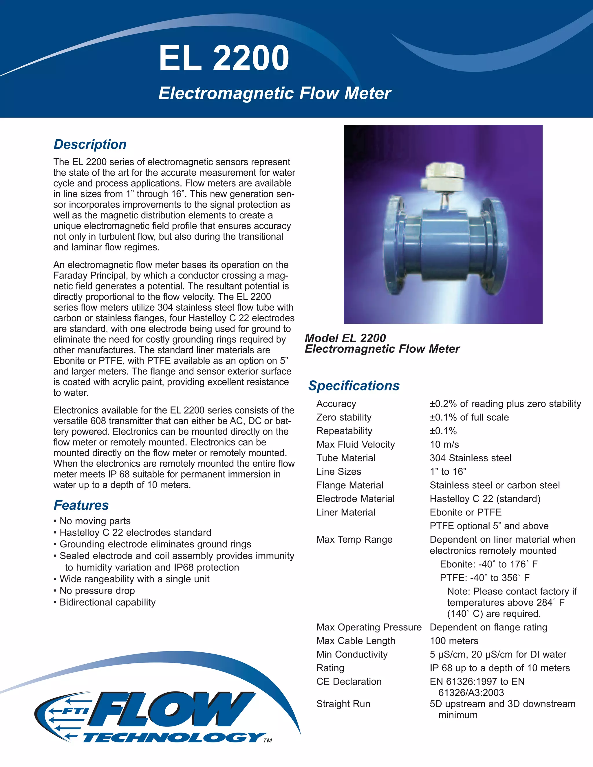


The EL 2200 series electromagnetic flow meters designed for accurate measurement in water cycle and process applications are available in sizes from 1” to 16” and feature materials like 304 stainless steel, Hastelloy C 22 electrodes, and ebonite or PTFE liners. These meters operate based on the Faraday principle and provide advanced signal protection and functionality at varying flow conditions, with a maximum fluid velocity of 10 m/s and optional high-temperature configurations. The versatile MC 608 transmitter allows for various powering options and configurations, enhancing liquid flow management with built-in memory and data logging capabilities.


