The document discusses the significance of mesh independence in CFD analysis of combustion systems, emphasizing the impact of domain discretization on results. It presents a study using three different mesh configurations, highlighting that increased refinement leads to more accurate representations of velocity distributions and flame patterns. The findings indicate that while refining the mesh enhances solution accuracy, it also doubles computation time.

![www.heatflux.com
[Min.]
[Max.]
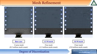
Base case 1.5 M mesh 3.0 M mesh
Average throat velocity ~ 31 ft/s Average throat velocity ~ 23 ft/s Average throat velocity ~ 23 ft/s
Velocity Contours at Burner Throat
❖ Observations:
▪ Base case to 1.5 M case: Significant difference in the velocity distribution at burner throat and average throat velocity.
▪ 1.5 M to 3.0 M case: Almost similar velocity distribution at burner throat.
❖ Conclusion:
▪ Base case (coarse mesh) does not give an ideal depiction of throat velocity distribution. Mesh refinement gives more accurate
distribution. An accurate throat velocity distribution will give an accurate flame pattern.
CFD Result: Velocity Distribution](https://image.slidesharecdn.com/importanceofmeshindependencestudy-180316045647/85/Importance-of-mesh-independence-study-5-320.jpg)
![www.heatflux.com
[Min.]
[Max.]
Flue Gas Velocity Contours
❖ As the mesh refinement is increased, the
flow from primary and staged tips become
more distinguished.
❖ Base case shows a combined flow pattern
which indicates that the flame would be from
a combined flow of tips.
❖ Velocity pattern for the other two cases show
that there will be lobes of staged fuel and a
central flame region due to primary fuel.
CFD Result: Velocity Distribution
Base case 1.5 M mesh 3.0 M mesh](https://image.slidesharecdn.com/importanceofmeshindependencestudy-180316045647/85/Importance-of-mesh-independence-study-6-320.jpg)
![www.heatflux.com
[Min.]
[Max.]
Flue Gas Velocity Contours
❖ Significant difference in the velocity profile
in the heater with a change in mesh
resolution.
❖ Ideal profile: Higher velocity at the center
with recirculated flow near the tubes and
walls
▪ This is obtained in 3.0 M mesh case.
▪ 1.5 M mesh case has flow tilted in one direction
▪ Base case has flow tilted towards the unshielded wall
CFD Result: Velocity Distribution
Base case 1.5 M mesh 3.0 M mesh](https://image.slidesharecdn.com/importanceofmeshindependencestudy-180316045647/85/Importance-of-mesh-independence-study-7-320.jpg)
![www.heatflux.com
Large recirculation on
one side
[Min.]
[Max.]
Flue Gas Velocity Vectors
❖ The density of vector in the images is
indicative of the mesh resolution.
❖ 3.0 M mesh case shows the best recirculation
pattern along with a more accurate depiction
of gas mixing from burner.
CFD Result: Velocity Flow Profile
Base case 1.5 M mesh 3.0 M mesh](https://image.slidesharecdn.com/importanceofmeshindependencestudy-180316045647/85/Importance-of-mesh-independence-study-8-320.jpg)
![www.heatflux.com
[Min.]
[Max.]
Flue Gas Temperature Contours
❖ Significant difference in the temperature
profile in the heater with a change in mesh
resolution.
❖ High flue gas temperature is observed near
the tubes in the first two cases (highlighted
regions)
CFD Result: Temperature Distribution
Base case 1.5 M mesh 3.0 M mesh](https://image.slidesharecdn.com/importanceofmeshindependencestudy-180316045647/85/Importance-of-mesh-independence-study-9-320.jpg)
![www.heatflux.com
Flame Height:
5.7 ft
(Based on an iso-
surface of CO)
Flame Height:
6.0 ft
Flame Height:
7.2 ft
[Min.]
[Max.]
Flame Height
❖ Large difference in the flame pattern
observed in the three cases
❖ Cases 2 and 3 with more refined meshes
indicate formation of lobes of the flame iso-
surface.
CFD Result: Flame Profile
Base case 1.5 M mesh 3.0 M mesh](https://image.slidesharecdn.com/importanceofmeshindependencestudy-180316045647/85/Importance-of-mesh-independence-study-10-320.jpg)
![www.heatflux.com
[Min.]
[Max.]
Radiant Tube Temperature Profile
❖ Mesh refinement has little impact on the
temperature pattern. However, most refined
mesh (3.0 M) indicates a value lower by 8 ºF.
❖ Slight difference in the temperature pattern is
observed on the highlighted tubes
CFD Result: Heat Distribution on Tubes
Base case 1.5 M mesh 3.0 M mesh](https://image.slidesharecdn.com/importanceofmeshindependencestudy-180316045647/85/Importance-of-mesh-independence-study-11-320.jpg)