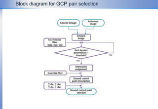
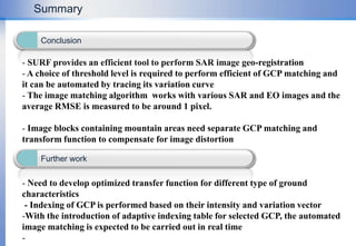
An Efficient Automatic Geo-registration Technique for High Resolution Spaceborne SAR Image FusionIGARSS 201128/July 2011Woo-Kyung Lee and A.R. KimKorea Aerospace Universitywklee@kau.ac.kr
Motivation As the resolution level improves,  * the unique feature of the radar imaging becomes prominent and the task of image fusion with optical image becomes complicated,   * the number of pixels increases and the amount of resources for calculation such as memory and time consumption escalates exponentially. To relieve the burden of the work and make it done in real time.Efficient image matching in both rural and urban regionsSimple approach to the SAR image registration and fusionLet the machine do the rest of the job in almost real timeOne click
SAR SensorandGeometricCharacteristicImage processing depends on thesurface characteristics and structures
Radar images suffer from unrealistic distortions
Non-linear distortions along range, Shortening from shadow region
Inaccurate Doppler parameter estimation leads to geocoding errors
Unstability in internal system clock and orbit parametersSystem error Side-looking ObservationSAR vs. optics  imagesImage acquisition
SAR SensorandGeometricCharacteristicEffect of ErrorError SourceSAR sensor - Electronic Time Delay - Slant Range Error - Incidence Angle Estimation - PRF FluctuationEffect of Error - Range Location - Range Scale  - Azimuth ScaleError correction method- Geometric Calibration- Deskew - Ground Projection - Image Rotation - Terrain CorrectionEarth - Azimuth Skew - Range Non-Linearity - Foreshortening, Layover,    ShadowingEarth - Earth Rotation - Side-looking - Target HeightSource of SAR geocoding errors Platform - Image Orientation Error - Squint Angle - Doppler CentroidPlatform - Inclination Angle - Yaw Angel Error - Pitch Angle Error
SAR SensorandGeometricCharacteristicMismatch between SAR and Optical imagesOpticsSARGeometrical  distortions in SAR images(a) Azimuth Distortion(b) Non linear Range Error(c) Deskew
SAR Geo-correction with satellite internal dataSlant range function has non linear scale variationsAzimuthSlant range imageRangeSland basedGround range imageGround projection exampleReference image(EO image)Ground BasedDiscrepancy exist compared with the reference image
Distortion between SAR and EO are case-sensitiveGCP based geometry registrationA reference image is chosen to be used for geometric correction or fusion
Multiple GCP(Ground Center Point)s are selected and directly applied to individual position error calculation and correction i
Based on the selected GCPs, image transforml function is characterized that best describes the discrepancy between the images
 Original image is re-sampled and re-arranged by the generated transform function
To perform geometrical calibration and restore distortion, the GCPs in the SAR images would be re-arranged into the true ground positions
It becomes most essential to pick up the best candidates of GCPsBasic PrincipleChoice of GCPIn general, distinctive features such as road, building, bridges, reflectors are chosen that are easily discriminated for convenience
Manually? Or Automatically?? Who will chose what points??Selection of GCPs within SAR images Speckle noise inherence in SAR image makes it difficult to guarantee to pinpoint precise positions that correspond to the reference points.
A human work of manual GCP selection is never reliable
The number of available points are case-sensitive and still limited by the existence of the distinctive features
The precision of the GCP location is not fully guaranteed and the error variance may increase in coarse resolution images. Difficulty of GCP choiceSAR image GCPOptical image GCP
MethodologySpeeded-Up Robust Features (SURF) is known to have highly robust  performance
Scale, rotation and illumination-invariant feature descriptor.
Adaptive for noisy environment and mutll-scale images- Only summing operation is involved in producing integral image to match the scale and calculation is speeded up Selection of matching points(GCP) are performed using feature vectors described by Hessian Matrix
The size of the constructed Hessian matix can be varied and can be increased to multiple dimensions as desired
The number of dimensions is limited by the complexity, time consumption and precision of the image matching.- case sensitive
Parameters required for the decision algorithms is set intuitively
This work is motivated to find the decision parameters automatically compromising the performance and the complexitySURF algorithmSelection of GCP and matching
                                           Block diagram for GCP pair selection
Integral image generationFor the given image, an integral set of points are summed together
The size is variable depending on the scale and complexity of the image
Simple summations of intensity levels are performed over two dimensional domain: A +B +C + D
GCP candidate generationThe Hessian matrix , corresponding to each pixel, is simplified by summation with adjacent cells
The image scale is varied and the simplified Hessian matrix is obtained for each scale space

IGARSS presentation WKLEE.pptx

  • 1.
    An Efficient AutomaticGeo-registration Technique for High Resolution Spaceborne SAR Image FusionIGARSS 201128/July 2011Woo-Kyung Lee and A.R. KimKorea Aerospace Universitywklee@kau.ac.kr
  • 2.
    Motivation As theresolution level improves, * the unique feature of the radar imaging becomes prominent and the task of image fusion with optical image becomes complicated, * the number of pixels increases and the amount of resources for calculation such as memory and time consumption escalates exponentially. To relieve the burden of the work and make it done in real time.Efficient image matching in both rural and urban regionsSimple approach to the SAR image registration and fusionLet the machine do the rest of the job in almost real timeOne click
  • 3.
    SAR SensorandGeometricCharacteristicImage processingdepends on thesurface characteristics and structures
  • 4.
    Radar images sufferfrom unrealistic distortions
  • 5.
    Non-linear distortions alongrange, Shortening from shadow region
  • 6.
    Inaccurate Doppler parameterestimation leads to geocoding errors
  • 7.
    Unstability in internalsystem clock and orbit parametersSystem error Side-looking ObservationSAR vs. optics imagesImage acquisition
  • 8.
    SAR SensorandGeometricCharacteristicEffect ofErrorError SourceSAR sensor - Electronic Time Delay - Slant Range Error - Incidence Angle Estimation - PRF FluctuationEffect of Error - Range Location - Range Scale - Azimuth ScaleError correction method- Geometric Calibration- Deskew - Ground Projection - Image Rotation - Terrain CorrectionEarth - Azimuth Skew - Range Non-Linearity - Foreshortening, Layover, ShadowingEarth - Earth Rotation - Side-looking - Target HeightSource of SAR geocoding errors Platform - Image Orientation Error - Squint Angle - Doppler CentroidPlatform - Inclination Angle - Yaw Angel Error - Pitch Angle Error
  • 9.
    SAR SensorandGeometricCharacteristicMismatch betweenSAR and Optical imagesOpticsSARGeometrical distortions in SAR images(a) Azimuth Distortion(b) Non linear Range Error(c) Deskew
  • 10.
    SAR Geo-correction withsatellite internal dataSlant range function has non linear scale variationsAzimuthSlant range imageRangeSland basedGround range imageGround projection exampleReference image(EO image)Ground BasedDiscrepancy exist compared with the reference image
  • 11.
    Distortion between SARand EO are case-sensitiveGCP based geometry registrationA reference image is chosen to be used for geometric correction or fusion
  • 12.
    Multiple GCP(Ground CenterPoint)s are selected and directly applied to individual position error calculation and correction i
  • 13.
    Based on theselected GCPs, image transforml function is characterized that best describes the discrepancy between the images
  • 14.
    Original imageis re-sampled and re-arranged by the generated transform function
  • 15.
    To perform geometricalcalibration and restore distortion, the GCPs in the SAR images would be re-arranged into the true ground positions
  • 16.
    It becomes mostessential to pick up the best candidates of GCPsBasic PrincipleChoice of GCPIn general, distinctive features such as road, building, bridges, reflectors are chosen that are easily discriminated for convenience
  • 17.
    Manually? Or Automatically??Who will chose what points??Selection of GCPs within SAR images Speckle noise inherence in SAR image makes it difficult to guarantee to pinpoint precise positions that correspond to the reference points.
  • 18.
    A human workof manual GCP selection is never reliable
  • 19.
    The number ofavailable points are case-sensitive and still limited by the existence of the distinctive features
  • 20.
    The precision ofthe GCP location is not fully guaranteed and the error variance may increase in coarse resolution images. Difficulty of GCP choiceSAR image GCPOptical image GCP
  • 21.
    MethodologySpeeded-Up Robust Features(SURF) is known to have highly robust performance
  • 22.
    Scale, rotation andillumination-invariant feature descriptor.
  • 23.
    Adaptive for noisyenvironment and mutll-scale images- Only summing operation is involved in producing integral image to match the scale and calculation is speeded up Selection of matching points(GCP) are performed using feature vectors described by Hessian Matrix
  • 24.
    The size ofthe constructed Hessian matix can be varied and can be increased to multiple dimensions as desired
  • 25.
    The number ofdimensions is limited by the complexity, time consumption and precision of the image matching.- case sensitive
  • 26.
    Parameters required forthe decision algorithms is set intuitively
  • 27.
    This work ismotivated to find the decision parameters automatically compromising the performance and the complexitySURF algorithmSelection of GCP and matching
  • 28.
  • 29.
    Integral image generationForthe given image, an integral set of points are summed together
  • 30.
    The size isvariable depending on the scale and complexity of the image
  • 31.
    Simple summations ofintensity levels are performed over two dimensional domain: A +B +C + D
  • 32.
    GCP candidate generationTheHessian matrix , corresponding to each pixel, is simplified by summation with adjacent cells
  • 33.
    The image scaleis varied and the simplified Hessian matrix is obtained for each scale space