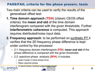
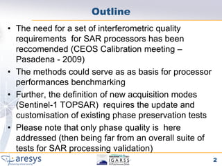
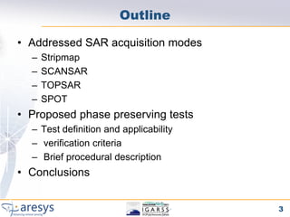
Phase preserving tests were proposed for SAR processors to validate their performance on different acquisition modes like Stripmap, ScanSAR, TOPSAR and SPOT. The tests include an extended CEOS offset test to verify phase preservation with shifts and scaling. An inter-burst/slice test verifies phase preservation between adjacent bursts by analyzing targets in overlap areas. An inter-swath test similarly analyzes overlapping sub-swaths. The tests evaluate time domain and frequency domain phase errors to screen for processor-induced artifacts.
![Classical CEOS offset test
Process two SLCs from the same raw data set and with the same orbit, but offset by
l00 lines in azimuth and l00 sample in range. The interferogram formed from these
two properly coregistered SLCs should ideally have a constant phase of zero and
thus reveals processor induced artifacts.
Pass/Fail criteria:
•Mean of interferogram phase ≤ 0.1°
•Standard deviation ≤ 5.5°
•No discontinuity at block boundaries.
[1] Rosich Tell B. and H Laur. Phase preservation in sar processing: the interferometric offset
test. In IGARSS96, Lincoln, Nebraska, USA, 27-31 May 1996.
6](https://image.slidesharecdn.com/phaserequirements-v1-2-110729123030-phpapp02/85/PhaseRequirements_v1_2-pdf-6-320.jpg)
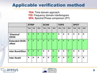
![Proposed SAR processor phase verification tests
Purpose STRIP SCAN TOPS SPOT
‘Classical’ CEOS The purpose of the “CEOS offset test“([1]) is to YES YES NO NO
verify the processor phase preservation
performances with respect to range and azimuth
shifts of the input RAW data. The test as it is
defined can be applied to STRIPMAP and
SCANSAR data
Extended CEOS offset The extended CEOS has been introduced in YES YES YES YES
order to verify the processor phase preservation
with respect to shifts and scaling.
Further the extended CEOS has been extended
to TOPSAR and SPOT modes
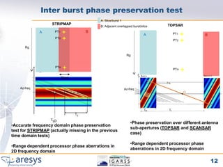
Inter Burst/Slice phase The purpose of this test is to verify the YES* YES YES NO
preserving processor phase preservation performances
when comparing the phase of adjacent bursts.
For this purpose , targets in the burst
overlapped area are exploited.
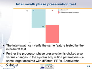
Inter Swath phase Same as inter-burst test but applied to Sub- NO YES YES NO
preserving swaths overlapping areas
[1] Rosich Tell B. and H Laur. Phase preservation in sar processing: the interferometric offset test. In IGARSS96,
Lincoln, Nebraska, USA, 27-31 May 1996.
* For STRIPMAP the InterBurst test is simply performed considering overlapping processing blocks
7](https://image.slidesharecdn.com/phaserequirements-v1-2-110729123030-phpapp02/85/PhaseRequirements_v1_2-pdf-7-320.jpg)