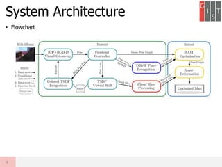
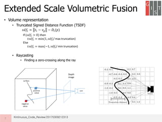
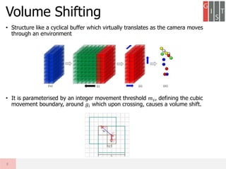
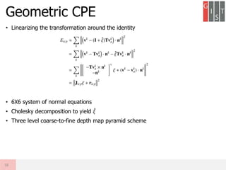
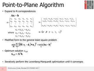
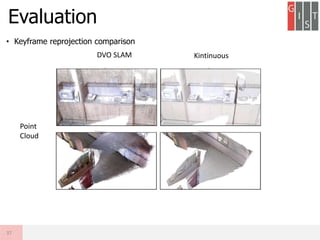
Real-time large scale dense RGB-D SLAM with volumetric fusion extends KinectFusion to larger scales. It represents the volumetric reconstruction as a rolling buffer that translates as the camera moves. It estimates camera pose through combined geometric and photometric constraints. It closes loops by non-rigidly deforming the map with constraints from loop closures and jointly optimizes the camera poses and map. Evaluation shows it produces large, globally consistent, real-time dense reconstructions.


![• Pose graph optimisation
• Carried out by the iSAM framework
• Map deformation
• cost functions over the deformation graph
• 1) maximising rigidity in the deformation
• 2) Regularisation term
• 3) Constraint term that minimises the error on a set of user specified vertex position constraints
Q
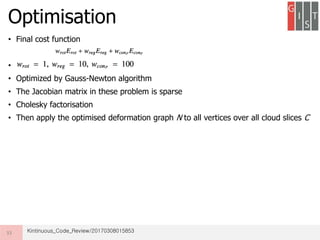
Optimisation
32
Graph node
neighbors
[𝑁𝑙
𝑅
, 𝑁𝑙
𝑡
, 𝑁𝑙
𝑔
]
[𝑁 𝑛
𝑡
, 𝑁 𝑛
𝑔
]](https://image.slidesharecdn.com/kintinuousreview-170521105711/85/Kintinuous-review-26-320.jpg)


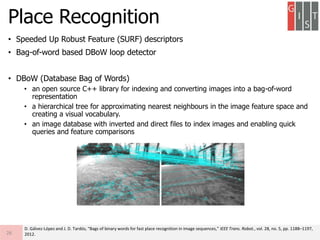
![Polymer [ बहुलक ] Chemistry Notes PDF - Irfanullah Mehar - JJ Sir Chemistry.pdf](https://cdn.slidesharecdn.com/ss_thumbnails/polymerchemistrynotespdf-irfanullahmehar-jjsirchemistry-260210172118-3f9b37f7-thumbnail.jpg?width=640&height=640&fit=bounds)


![ANIMAL_CELL_,_TISSUE_AND_ORGAN_CULTURE[1].pptx](https://cdn.slidesharecdn.com/ss_thumbnails/animalcelltissueandorganculture1-260204172026-4462b440-thumbnail.jpg?width=640&height=640&fit=bounds)


