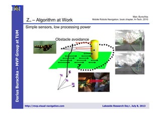
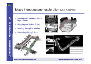
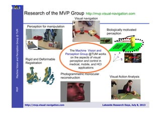
Darius Burschka presents work on collaborative visual-SLAM approaches using mini-UAVs. The key aspects discussed are:
1) Using omnidirectional cameras instead of fish-eye lenses to allow easy recovery of viewing angles for localization and reconstruction.
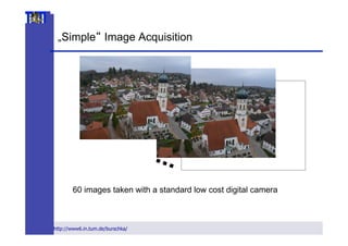
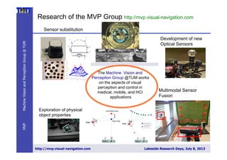
2) Proposing measures like increasing distance between cameras, focal length, or camera resolution to boost perception resolution in camera swarms.
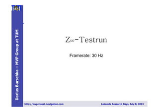
3) Describing a collaborative reconstruction approach using two independently moving cameras to estimate extrinsic parameters and reconstruct 3D points from motion stereo without extrinsic calibration.

![DariusBurschka–MVPGroupatTUM
http://mvp.visual-navigation.com Lakeside Research Days, July 8, 2013
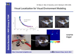
Aspects of Collaborative Swarm Perception
4 Darius Burschka
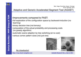
Fig. 2. Collaborative 3D reconstruction from 2 independently moving cameras.
directional system with a large field of view.
We decided to use omnidirectional systems in-
stead of fish-lens cameras, because their single view-
point property [2] is essential for our combined
localization and reconstruction approach (Fig. 3).
ep2008
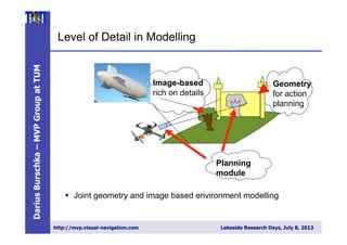
• What is the appropriate level of
detail for model representation?
• How to boost measurement
sensitivity at large distances?
• Global vs. local perception?
• Increase the exploration speed by
sharing the exploration of free
space
• Completeness of the
instantaneous scene perception –
true 3D instead of 2.5D](https://image.slidesharecdn.com/lakesideresearchdays-130711085925-phpapp02/85/Fusion-of-Multi-MAV-Data-2-320.jpg)

![DariusBurschka–MVPGroupatTUM
http://mvp.visual-navigation.com Lakeside Research Days, July 8, 2013
__________________________________________________________________
__________________________________________________________________
______________________________________________
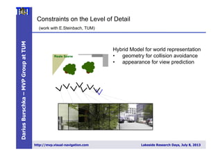
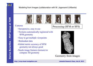
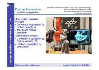
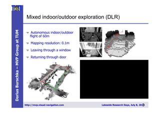
Swarms to boost resolution
Possible measures:
• Increase of the distance
between cameras (B)
• Increase of the focal length
(f) → field of view
• Decrease of the pixel-size
(px) → resolution of the
camera
[ ]pixel
zp
fB
d
x
p
1
⋅
⋅
=
75cm](https://image.slidesharecdn.com/lakesideresearchdays-130711085925-phpapp02/85/Fusion-of-Multi-MAV-Data-20-320.jpg)
![DariusBurschka–MVPGroupatTUM
http://mvp.visual-navigation.com Lakeside Research Days, July 8, 2013
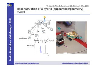
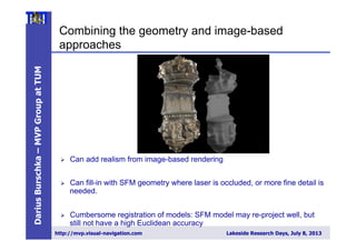
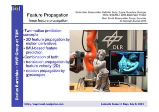
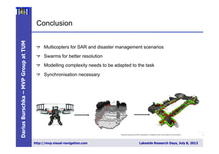
Collaborative Reconstruction with Self-Localization
(CVPR Workshop on Vision in Action: Efficient strategies for
cognitive agents in complex environments, Marseille : France (2008))
4 Darius Burschka
Fig. 2. Collaborative 3D reconstruction from 2 independently moving cameras.
directional system with a large field of view.
We decided to use omnidirectional systems in-
stead of fish-lens cameras, because their single view-
point property [2] is essential for our combined
localization and reconstruction approach (Fig. 3).
This property allows an easy recovery of the viewing
angle of the virtual camera with the focal point F
(Fig. 3) directly from the image coordinates (ui, νi).
A standard perspective camera can be mapped on
1-30Sep2008
in [3]. The original approach relied on an essential method to initialize the
3D structure in the world. Our system gives a more robust initialization method
minimizing the image error directly. The limited space of this paper does not
allow a detailed description of this part of the system. The recursive approach
from [3] is used to maintain the radial distance λx.
3 Results
Our flying systems use omnidirectional mirrors like the one depicted in Fig. 6
Fig. 6. Flying agent equipped with an omnidirectional sensor pointing upwards.
We tested the system on several indoor and outdoor sequences with two cam-
eras observing the world through different sized planar mirrors (Fig. 4) using a
Linux laptop computer with a 1.2 GHz Pentium Centrino processor. The system
was equipped with 1GB RAM and was operating two Firewire cameras with
standard PAL resolution of 768x576.
3.1 Accuracy of the Estimation of Extrinsic Parameters
We used the system to estimate the extrinsic motion parameters and achieved
results comparable with the extrinsic camera calibration results. We verified
the parameters by applying them to the 3D reconstruction process in (5) and
achieved measurement accuracy below the resolution of our test system. This
reconstruction was in the close range of the system which explains the high
inria-00325805,version1-30Sep2008
of the camera f=1) (ui, νi) to
ni =
(ui, νi, 1)T
||(ui, νi, 1)T ||
.
We rely on the fact that each camera can see the partner and the area
wants to reconstruct at the same time.
In our system, Camera 1 observes the position of the focal point F o
era 2 along the vector T , and the point P to be reconstructed along the ve
simultaneously (Fig. 2). The second camera (Camera 2) uses its own coo
frame to reconstruct the same point P along the vector V2. The point P o
by this camera has modified coordinates [10]:
V2 = R ∗ (V1 + T )
Collaborative Exploration - Vision in Actio
Since we cannot rely on any extrinsic calibration, we perform the c
of the extrinsic parameters directly from the current observation. W
find the transformation parameters (R, T) in (3) defining the trans
between the coordinate frames of the two cameras. Each camera define
coordinate frame.
2.1 3D Reconstruction from Motion Stereo
In our system, the cameras undergo an arbitrary motion (R, T ) whi
in two independent observations (n1, n2) of a point P. The equation (
written using (2) as
λ2n2 = R ∗ (λ1n1 + T ).
We need to find the radial distances (λ1, λ2) along the incoming rays to
the 3D coordinates of the point. We can find it by re-writing (4) to
(−Rn1, n2)
λ1
λ2
= R · T
λ1
λ2
= (−Rn1, n2)
−∗
· R · T = D−∗
· R · T
We use in (5) the pseudo inverse matrix D−∗
to solve for the two unk
Collaborative Exploration - Vision in Action
Since we cannot rely on any extrinsic calibration, we perform the calibrat
of the extrinsic parameters directly from the current observation. We need
find the transformation parameters (R, T) in (3) defining the transformat
between the coordinate frames of the two cameras. Each camera defines its o
coordinate frame.
2.1 3D Reconstruction from Motion Stereo
In our system, the cameras undergo an arbitrary motion (R, T ) which resu
in two independent observations (n1, n2) of a point P. The equation (3) can
written using (2) as
λ2n2 = R ∗ (λ1n1 + T ).
We need to find the radial distances (λ1, λ2) along the incoming rays to estim
the 3D coordinates of the point. We can find it by re-writing (4) to
(−Rn1, n2)
λ1
λ2
= R · T
λ1
λ2
= (−Rn1, n2)
−∗
· R · T = D−∗
· R · T
We use in (5) the pseudo inverse matrix D−∗
to solve for the two unknown
dial distances (λ1, λ2). A pseudo-inverse matrix to D can be calculated accord
to
D−∗
= (DT
· D)−1
· DT
.
The pseudo-inverse operation finds a least square approximation satisfying
overdetermined set of three equations with two unknowns (λ , λ ) in (5). D
1-30Sep2008
Collaborative Exploration - Vision in Action
Since we cannot rely on any extrinsic calibration, we perform the calibr
of the extrinsic parameters directly from the current observation. We nee
find the transformation parameters (R, T) in (3) defining the transform
between the coordinate frames of the two cameras. Each camera defines its
coordinate frame.
2.1 3D Reconstruction from Motion Stereo
In our system, the cameras undergo an arbitrary motion (R, T ) which re
in two independent observations (n1, n2) of a point P. The equation (3) ca
written using (2) as
λ2n2 = R ∗ (λ1n1 + T ).
We need to find the radial distances (λ1, λ2) along the incoming rays to esti
the 3D coordinates of the point. We can find it by re-writing (4) to
(−Rn1, n2)
λ1
λ2
= R · T
λ1
λ2
= (−Rn1, n2)
−∗
· R · T = D−∗
· R · T
We use in (5) the pseudo inverse matrix D−∗
to solve for the two unknow
dial distances (λ1, λ2). A pseudo-inverse matrix to D can be calculated acco
to
D−∗
= (DT
· D)−1
· DT
.
The pseudo-inverse operation finds a least square approximation satisfyin
overdetermined set of three equations with two unknowns (λ1, λ2) in (5).
to calibration and detection errors, the two lines V1 and V2 in Fig. 2 do
necessarily intersect. Equation (5) calculates the position of the point a
each line closest to the other line.
5,version1-30Sep2008](https://image.slidesharecdn.com/lakesideresearchdays-130711085925-phpapp02/85/Fusion-of-Multi-MAV-Data-21-320.jpg)
![DariusBurschka–MVPGroupatTUM
http://mvp.visual-navigation.com Lakeside Research Days, July 8, 2013
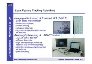
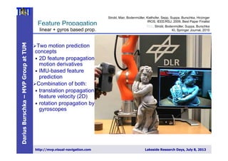
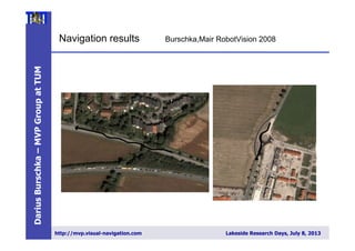
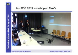
Condition number for an angular configuration
The relative error in the solution caused by perturbations of parameters can
stimated from the condition number of the pseudo-inverse matrix D−∗
. The
dition number is the ratio between the largest and the smallest singular value
his matrix [4].
The condition number estimates the sensitivity of the solution of a linear
braic system to variations of parameters in matrix D−∗
and in the measure-
t vector T .
Consider the equation system with perturbations in matrix D−∗
and vec-
T :
(D−∗
+ δD−∗
)Tb = λ + δλ (8)
The relative error in the solution caused by perturbations of parameters can
stimated by the following inequality using the condition number κ calculated
D−∗
(see [7]):
||T − Tb||
||T ||
≤ κ
||δD−∗
||
||D−∗||
+
||δλ||
||λ||
+ O( 2
) (9)
Therefore, the relative error in solution λ can be as large as condition num-
times the relative error in D−∗
and T . The condition number together with
singular values of the matrix D−∗
describe the sensitivity of the system
hanges in the input parameters. Small condition numbers describe systems
small sensitivity to errors compared to large condition numbers that suggest
llel direction of the measured direction vectors (n1, n2). A quantitative eval-
on of this result can be found in Section 3.2. We use the condition number of
matrix D−∗
as a metric to evaluate the quality of the resulting configuration
he two cameras. We can move the cameras for a given region of interest to
nfiguration with a small condition number ensuring high accuracy of the
nstructed coordinates.
f we know the extrinsic motion parameters (R, T ), e.g. from a calibration
ess, then equation (5) allows to estimate directly the 3D position of an ob-
The collaborative exploration approach allows us to move the cameras
desired position to establish the best sensitivity and the highest robustn
errors in the parameter estimation. We mentioned already in section 2.1
the sensitivity of the reconstruction result (5) to parameter errors depen
the relative orientation of the reconstructing cameras (Fig. 8).
−5
−3
−1
1
3
5
7
−5
0
5
−5
0
5
0
50
100
150
Orientation Cam 1 [deg]
Orientation Cam 2 [deg]
Conditionnumber
Fig. 8. (left) The condition number of the 3D reconstruction is dependent o
relative orientation of the corresponding direction vectors V1, V2 in Fig. 2 obser
point;(right) a minimal condition number corresponds to a difference in the v
Best observation by 90° viewing angle](https://image.slidesharecdn.com/lakesideresearchdays-130711085925-phpapp02/85/Fusion-of-Multi-MAV-Data-22-320.jpg)
![DariusBurschka–MVPGroupatTUM
http://mvp.visual-navigation.com Lakeside Research Days, July 8, 2013
Asynchronous stereo for dynamic scenes
4 Darius Burschka
Fig. 2. Collaborative 3D reconstruction from 2 independently moving cameras.
directional system with a large field of view.
Fig. 3. Single viewpoint
property.
We decided to use omnidirectional systems in-
stead of fish-lens cameras, because their single view-
point property [2] is essential for our combined
localization and reconstruction approach (Fig. 3).
This property allows an easy recovery of the viewing
angle of the virtual camera with the focal point F
(Fig. 3) directly from the image coordinates (ui, νi).
A standard perspective camera can be mapped on
our generic model of an omnidirectional sensor. The
only limitation of a standard perspective camera is
the limited viewing angle. In case of a standard per-
spective camera with a focal point at F, we can es-
timate the direction vector ni of the incoming rays
from the uni-focal image coordinates (focal length
of the camera f=1) (u , ν ) to
25805,version1-30Sep2008
NTP
Figure 2: Here: C0 and C1 are the camera centers of the
stereo pair, P0,P1,P2 are the 3D poses of the point at times
t0,t1,t2. Latter correspond to frame acquisition timestamps
of camera C0. P⇤ is the 3D pose of the point at time t⇤,
which correspond to the frame acquisition timestamp of the
camera C1. Vectors v0,v1,v2, are unit vectors pointing from
camera center C0, to corresponding 3D points. Vector v⇤ is
the unit vector pointing from camera center C to pose P⇤
Since the angle between the velocity dire
vector v3 and v0 is y, v3 and v2 is h, and v
ˆn is p
2 . We can compute the v3 by solving the fo
ing equation:
2
4
v0x v0y v0z
v2x v2y v2z
nx ny nz
3
5
2
4
v3x
v3y
v3z
3
5 =
2
4
cosy
cosh
0
3.2 Path Reconstruction
In the second stage of proposed method we com
the 3D pose P0. For reasons of simplicity we
represent the poses (Pi (i = 0..2), P⇤) depicted i
2 as:
Pi =
2
4
ai ⇤zi
bi ⇤zi
zi
3
5 P⇤ =
2
4
m⇤z⇤
0 +tx
s⇤z⇤
0 +ty
q⇤z⇤
0 +tz
3
5
where tx,ty,tz are the x,y and z componen
Submitted VISAPP 2014](https://image.slidesharecdn.com/lakesideresearchdays-130711085925-phpapp02/85/Fusion-of-Multi-MAV-Data-23-320.jpg)
![DariusBurschka–MVPGroupatTUM
http://mvp.visual-navigation.com Lakeside Research Days, July 8, 20132
5
Towards Autonomous MAV Exploration in Cluttered Indoor and Outdoor Environments > Korbinian Schmid > 28/06/2013
Slide
INS filter design
25
[Schmid et al. IROS 2012]
" Synchronization of realtime and non realtime modules by sensor hardware trigger
" Direct system state:
" High rate calculation by „Strap Down Algorithm“ (SDA)
" Indirect system state:
" Estimation by indirect Extended Kalman Filter (EKF)
" Measurements: „pseudo gravity“, key frame based stereo odometry
" Measurement delay compensation by filter state augmentation](https://image.slidesharecdn.com/lakesideresearchdays-130711085925-phpapp02/85/Fusion-of-Multi-MAV-Data-25-320.jpg)
![DariusBurschka–MVPGroupatTUM
http://mvp.visual-navigation.com Lakeside Research Days, July 8, 20132
9
Slide
INS filter design
29
[Schmid et al. IROS 2012]
" Synchronization of realtime and non realtime modules by sensor hardware trigger
" Direct system state:
" High rate calculation by „Strap Down Algorithm“ (SDA)
" Indirect system state:
" Estimation by indirect Extended Kalman Filter (EKF)
" Measurements: „pseudo gravity“, key frame based stereo odometry
" Measurement delay compensation by filter state augmentation](https://image.slidesharecdn.com/lakesideresearchdays-130711085925-phpapp02/85/Fusion-of-Multi-MAV-Data-29-320.jpg)


![Getting Started with Apache Spark: Big Data Made Simple [Free Meetup]](https://cdn.slidesharecdn.com/ss_thumbnails/apachesparkgettingstarted-260203175547-8361bcc3-thumbnail.jpg?width=640&height=640&fit=bounds)


