SlideShare a Scribd company logo
Engineeiing Ser~ces Examination-20f ~
[oo NOT OPEN THIS TEST BOOKLET UNTIL YOU ARE ASKED TO DO SO)
T.B.C. : B-FRF- M- DDB
Serial No. l l TEST BOOKLET
ELECTRICAL ENGINEERING PAPER- II
Test Booklet Series
A[Time Allowed : '/Wo Hours ( Maximum Marks : 200J
I.
2.
3.
4.
s.
6.
7.
INSTRUCTIONS
IMMEDIATELY AFTER THE COMMENCEMENT OF T HE EXAMINATION, YOU SHOULD
CHECK THAT THIS TEST BOOKLET DOES NOT HAVE ANY UNPRINTED OR TORN OR
MISS£NG PAGES OR ITEMS, ETC. IF SO, GET IT REPLACED BY A COMPLETE TEST BOOKLET.
PLEASE NOTE THAT IT IS THE CANDIDATE'S RESPONSIBILITY TO ENCODt: AND
FILL IN THE ROLL NUMBER AND TEST BOOKLET SERIES COm ; A, B, C OR D
CAREFULLY AND WITHOUT ANY OMISSION Oil DISCREPANCY AT THE APPROPRIATE
PLACES IN T HE OMR ANSWER SHEET. ANY OMISSION I DISCREPANCY WILL RENDER
THE ANSWER SHEET LIABLE FOR REJECTION.
You have to enter vour Roll Number on the Test Booklet in [ ]
the Box provided a longside. DO NOT write anything else
on the Test Bookie!. ' - - - -- - - - - - ----'
This Test Booklet contains 120 items (questions). Each item comprises four responses (answers).
You will select the response which you want to mark on the Answer Sheet. In case, you feel that
there is more than one correct response. mark the response which you consider the best. In any
case, choose ONLY ONE response for each item.
You have to mark your responses ONLY on the separate Answer Sheet provided. See directions
in the Answer Sheet.
All items carry equal marks.
Before you proceed to mark in tho Answer Sheet the response to various items in the Test Booklet,
you have to fill in some particulars in the Answer Sheet as per instructions seot to you with your
Admission Certificate.
8. After you have completed fill ing in all your responses on the Answer Sheet and the
examination has concluded, you should hand over to the lnvigilator only the Answer Shut. You are
permitted to take away with you the Test Booklet.
9. Sheets for rough work are append.ed in the Test Booklet at the end.
10. Penalty for wrong answers :
THERE WILL BE PENALTY FOR WRONG ANSWERS MARKED BY A CANDIDATE.
(i) There are four alternatives for the answer to every question. For each question for which a
wrong answer has been give n by the candidate. one-third of the marks assigned tO that
question will be deducted as penalty.
{ii) If a candidate gives more than one answer, it will be treated as wrong answer even if one of
the given answers happens to be correct and there will be same penalty as above to that question.
{iii) If a question is left blank, i.e. no answer is given by the candidate, there will be
no penalty for that question.
( DO NOT OPEN THIS TEST BOOKLET UNTIL YOU ARE AS KED TO DO SO)
www.examrace.com
I. When a transformer is first energized, the
transient current during first few cycles is :
(a) Less than full load current
(b) Equal to full load current
(c) Equal to no load current
(d) Much higher than full load current
2. For power transformers of larger ratings,
the tappings are located in the middle
portion of the winding to :
(a) Increase the break-down strength of
the winding insulation
(b) Enable better cooling ofthe windings
(c) Enable better distribution of inter-
tum voltage
(d) Reduce the mechanical forces
affecting tbe windings during short-
circuits
3. Tappings are normally provided on the
high voltage winding ofa transformer only,
because :
(a) lt has larger number of turns which
allows smoother variation of voltage
(b) It has to handle low currents
(c) It is easily accessible physically
(d) It has larger number of turns, has to
handle low currents and is also easily
accessible physically
4. Short circuit test is performed on a
transformer with a certain impressed
voltage at rated frequency. If the short
circuit test is now performed with the same
magnitude of impressed voltage, but at a
frequency higher than the rated frequency,
then tbe magnitude of current :
(a) And power-factor will both increase
(b) Will decrease but the power factor
will increase
(c) Will increase, but power factor will
decrease
(d) And power factor will both decrease
2
0
5. The impedance of a 6/Y, II 000 V/400 V,
transformer of capacity I 00 kVA, on its
name plate data base is (0.02 +j0.07) p.u.
The ohmic impedance p.u. phase referred
to the prirhary (II 000 V) side is :
(a) (0.02 + j 0.07) Q
{b) (0.55 + j 1.925) Q
(c) (42 + j 147) Q
(d) (72.6 + j 254.1) Q
6. A 2000 kVA, single-phase transformer is
in circuit continuously. For 8 hours in a
day, the load is 160 kW at 0.8 pf. For
6 hours, the load is 80 kW at unity pf and
for the period remaining out of 24 hours,
it runs on no-load. If the full-load copper
losses are 3.02 kW, the total copper losses
in 24 hours are :
(a) 35.62 kW
(b) 24.16 kW
(c) 11.46 kW
(d) 38.40 kW
7. A 50 kVA transformer has a core loss of
500 W and full-load core loss of 900 W.
The load at which the efficiency is
maximum is:
(a) 27.45 kVA
(b) 37.75 kVA
(c) 45.5 kVA
(d) 47.5 kVA
8. For a two-winding power transformer, with
the effects of the no-load current being
neglected, the 'Voltage Regulation' can
be zero at load, when the load power-
factor is :
(a) Lagging only
(b) Leading only
(c) Either lagging or leading, depending
upon power rating of tbe transformer
(d) Unity
(Contd.)
www.examrace.com
9. The ratio of primary/secondary voltages
is 2 : I. The saving in terms of weight of
copper required if an autotransformer is
used instead ofa two-winding transformer
will be :
(a) 95%
(b) 66.7%
(c) 50%
(d) 33.3%
I0. Consider the following statements
concerning the utility of mesh-connected
tertiary winding,s in star-star transformers :
I. It is used to suppress harmonic
voltages
2. It is used to allow flow ofearth fault
current for operation of protective
devices
3. It facilitates supply of single-phase
loads
4. It provides low-reactance paths for
zero sequence currents
Which of these statements are correct ?
(a) 1, 2, 3 and 4
(b) I. 2 and 3 only
(c) I, 2 and 4 only
(d) 3 and 4 only
II . The most essential condition for parallel
operation of two 1-41 transformers is that
they should have the same :
(a) kVA rating
(b) Percentage impedance
(c) Polarity
(d) Voltage ratio
3
0
12. Two single-phase 100 kVA transformers,
each having different leakage impedances
are connected in parallel. When a load of
150 kVA at 0.8 power factor lagging is
applied :
(a) Both transformers will operate at
power factor more than 0.8 lagging
(b) Both transformers will operate at
power factor less than 0.8 lagging
(c) One of the transformers will operate
at power factor more than 0.8 lagging
and other will operate at power factor
less than 0.8 lagging
(d) Both transformers will operate at
identical power factors
13. A triangular mmf wave is produced in
the air-gap of an electric machine. Such
a wave is produced by :
(a) Stator of an induction machine
(b) Rotor of a synchronous machine
(c) Stator of a de machine
(d) Rotor of a de machine
14. At 1200 rpm the induced emf of a de
machine is 200 V. For an armature current
of 15 A the electromagnetic torque
produced would be :
(a) 23.8 N-m
(b) 238 N-m
(c) 2000 N-m
(d) 3000 N-m
(Contd.)
www.examrace.com
15. A 4-pole lap wound de generator has a
developed power of P watt and voltage
of E volt. Two adjacent brushes of the
machine are removed as they are worn
out. If the machine operates with the
remaining brushes, the developed voltage
and power that can be obtained frQm the
machine are :
(a) E and P
(b) E/2 and P/2
(c) E and P/4
(d) E and P/2
16. A 6-pole de armature has simplex lap-
connected 720 conductors, 3 turns per coil
and 4 coil-sides per slot. Determine the
number of slots in the armature and state
whether equalizers can be employed or
not.
(a) 60 slots and Not Possible
(b) 30 slots and Possible
(c) 60 slots and Possible
(d) 30 slots and Not Possible
17. Oetennine the flux per pole for 6-po1e de
machine having 240 wave connected
conductors, which generates an open circuit
voltage of 500 volt, which is running at
1000 rpm.
(a) 0.129 Wb
(b) 0.021 Wb
(c) 0.042 Wb
(d) 7 mWb
4
0
18.
19.
20.
Consider the following statements :
The armature reaction mmf in a de machine
is :
I. Stationary with respect to the field
poles
2. Rotating withrespect to the field poles
3. Rotating with respect to the arn1ature
Which of these statements are correct ?
(a) I, 2 and 3
(b) l and 2 only
(c) 1 and 3 only
(d) 2 and 3 only
In case ofde motor, maximum mechanical
power is developed when back emf
equals :
(a) The applied voltage
(b) Half the applied voltage
(c) One third of the applied voltage
(d) Double the applied voltage
The induced emfofa de machine running
at 750 rpm is ~20 V. The percentage
increase in field flux for generating an
induced emf of 250 V at 700 rpm would
be :
(a) 7%
(b) 11.25%
(c) 21.7%
(d) 42.4%
(Contd.)
www.examrace.com
21 . 1be speed ofa sepamtely excited de motor
is varied by varying the armature voltage
in the range zero to base speed and by
varying the field current above the base
speed. It is suitable for constan1 :
(a) Torque drive at all speeds
(b) Power drive at all speeds
(c) Torque drive till base speed and
constant power drive beyond base
speed
(d) Power drive till base speed and
constant torque drive beyond base
speed
22. A de shunt motor is required to drive a
constant power load at rated speed while
drawing rated armature current. Neglecting
satumtion and all machine losses, if both
the terminal voltage and the field current
of the machine are halved then :
(a) The speed becomes 2 pu but armature
current remains at I pu
(b) The speed remains at I pu but
armature current becomes 2 pu
(c) Both speed and armature current
become 2 pu
(d) Both speed and armature current
remain at I pu
23. The de series motor is best suited for
traction work, because :
(a) Torque is proportional to the square
of armature current and speed is
inversely proportional to torque
(b) Torque is proportional to the square
of armature current and speed is
directly proportional to torque
(c) Both torque and speed are
proportional to the square ofarmature
current
(d) Torque is proportional to armature
current and speed is inversely
proportional to torque
5
0
24. A 3-phase synchronous motor with constant
excitation is driving a certain load drawing
electric power from inftnite bus at leading
power factor. If the shaft load decreases :
(a) The power angle decreases while
power factor increases
(b) The power angle increases while
power factor decreases
(c) Both power angle and power factor
increase
(d) Both power angle and power factor
decrease
25. The maximum power delivered by 1500 kW.
3-phase, star-connected, 4 kV, 48 pole
50 Hz synchronous motor, with
synchronous reactance of 4 n per phase
and unity power factor :
(a) 4271.2 kW
.(b) 3505 kW
(c) 1206.1 kW
(d) 2078 kW
26. Consider the following statements
regarding synchronous machines :
I. When a synchronous motor is over-
excited, its back emf is greater than
the supply voltage
2. When a synchronous motor is over-
excited, its power factor is leading
3. Synchronous motor is used as
capacitor where load is so large that
construction of a static capacitor is
impractical
Which of these statements are correct ?
(a) I and 2 only
(b) I and 3 only
(c) 2 and 3 only
(d) I, 2 and 3
(Contd.)
www.examrace.com
27. In TV transmission, picture signal is
amplitude modulated and sound signal is
frequency modulated. This is done
because :
(a) It is not possible to frequency
modulate the picture signal
(b) Band width requirement is minimized
(c) Sound signal is more susceptible to
noise than picture signal
(d) Synchronization of picture frames
becomes easier
28. A system has a receiver noise resistance
of 50 Q. It is connected to an antenna
with an output resistance of 50 Q. The
noise figure of the system is :
(a)
(b) 2
(c) 50
(d) 10I
29. The power gain of an antenna using
paraboloid reflector is directly proportional
to :
(a) Mouth diameter
(b) Wavelength
(c) Aperture ratio
(d) Square of aperture ratio
6
0
30. A binary channel with capacity of 36 kbitsl
sec is available for PCM voice
transmission. If signal is band limited to
3.2 kHz, then the appropriate values of
quantizing level L and the sampling
frequency respectively are :
(a) 32 and 3.6 kHz
(b) 64 and 7.2 kHz
(c) 64 and 3.6 kHz
(d) 32 and 7.2 kHz
31. A 8-bit AID convertor is used over a span
ofzero to 2.56 V. l11e binary representation
of 1.0 V signal is :
(a) Oil 001 00
(b) 011 100 01
(c) 101 001 Ol
(d) 101 000 10
32. RF carrier 10 kV at I MHz is amplitude
modulated and modulation index is 0.6.
Peak voltage of the signal is :
(a) 600 kV
(b) 1200 kV
(c) 6 kV
(d) 10 kV
33. Output data ratio of a 8-bit PCM-TDM
system sampling 24 voice channels,
comparing these using 11-law at the rate
of 8 kHz and with a I frame alignment
word, is :
(a) 1.2 X I06 bits/sec
(b) 1.4 )( l06 bits/sec
(c) 1.6 X I06 bits/sec
(d) 1.8 X l 06 bits/sec
(Contd.)
www.examrace.com
34. 24 voice channels are sampled uniformly
at a rate of 8 kHz and then time division
multiplexed. Tite sampling process uses
flat-top samples with 1 llS duration. The
multiplexing operation includes provision
ofsynchronization by adding an exua pulse
of I llS duration. The spacing between
successive pulses of the multiplexed signal
is :
(a) 4 llS
(b) 6 llS
(c) 7.2 llS
(d) 8.4 llS
35. A signal is passed through a LPF with
cut-off frequency I 0 kHz. The minimum
sampling frequency is :
(a) 5kHz
(b) 10kHz
(c) 20kHz
(d) 30kHz
36. The main advantage of time division
multiplexing (TDM) over frequency
division multiplexing (FDM) is that it :
(a) Requires less bandwidth
(b) Requires less power
(c) Requires simple circuitry
(d) Provide better signal-to-noise ratio
37. The advantage of hydro-electric power
station over thermal power station is :
(a) The initial cost of hydro-electric
power station is low
(b) The operating cost of hydro-electric
power station is low
(c) Hydro-electric power station can
supply the power throughout the year
(d) Hydro-electric power station can be
constructed at the place where the
energy is required
7
0
38. The incremental cost characteristics oftwo
generators delivering 200 MW are as
follows :
dF.
- 2 = l.6+0.02P2dP2
For economic operation the generation P1
and P2 should be :
(a) 100 MW and 100 MW
(b) 80 MW and 120 MW
(c) 200 MW and 100 MW
(d) 120 MW and 80 MW
39. No load test was conducted on a three
phase induction motor at different input
voltages and the input power obtained was
plotted against the input voltage. The inter-
section of the extrapolated curve on the
Y-axis, would give :
(a) Rated core loss
(b) Windage and friction loss
(c) Rated copper loss
(d) Rated core loss and Windage and
friction loss
40.. A power generating station has a maximum
demand of lOOO MW. The annual load
factor is 75% and plant capacity factor is
60%. Calculate the reserve capacity.
(a) 250 MW
(b) 500 MW
(c) 750 MW
(d) 1250 MW
(Contd.)
www.examrace.com
41. In order to have lower cost of power
generation :
(a) The load factor and diversity factor
should be low
(b) The load factor and diversity factor
should be high
(c) The load factor should be low but
diversity factor should be high
(d) The load factor should be high but
diversity factor should be low
42. Consider the following statements :
The calculation performed using short line
approximate model instead ofnominal-n
model for a medium length transmission
line delivering lagging load at a given
receiving end voltage always results in
higher :
I. Sending end current
2. Sending end power
3. Regulation
4. Efficiency
Which of these statements are correct ?
(a) I and 2 only
(b) 2 and 3 only
(c) I, 2 and 4
(d) l, 3 and 4
8
D
43. The locus of constant received power is
a circle of radius :
44. Consider the following statements
regarding convergence of the Newton-
Raphson procedure :
I. It does not converge to a root when
the second differential coefficient
changes sign
2. It is preferred when the graph of (X)
is nearly horizontal where it crosses
the X-axis
3. It is used to solve algebraic and
transcendental equations
Which of these statements are correct ?
(a) I, 2 and 3
(b) 1 and 2 only
(c) 2 and 3 only
(d) I and 3 only
(Contd.)
www.examrace.com
45. The Positive, Negative and Zero sequence
per unit impedances of two generators
connected in parallel are X1
= 0.12,
X2 = 0.096 and ~ = 0.036 pu. For a
L-G fault at generator terminals (with
I pu voltage) the positive sequence current
will be :
(a) 7.936 pu
(b) 11.936 pu
(c) 10.936 pu
(d) 8.936 pu
46. A 50 MVA, II kV, 3-phase generator has
a stored energy of 400 M.J. Its inertia
constant is :
(a) 4
(b) 8
(c) 2
(d) 16
47. The steady state stability limit of a
synchronous machine connected to infinite
bus is 2.2 pu. Infinite bus voltage is I pu
and synchronous machine voltage is
1.1 pu. The transfer reactance between
generator and infinite bus is :
(a) j 0.5
(b) -j 0.5
(c) j 1.0
(d) -j 1.0
48. Two identical synchronous machines
having same inertia constant are connected
in parallel and swinging together. The
effective inertia constant is 4 MJ/MVA.
Then each machine has an inertia constant
of:
(a) 2 MJ/MVA
(b) 4 MJ/MVA
(c) 8 MJ/MVA
(d) 16 MJIMVA
49. A large ac generator supplying power to
an infinite bus is suddenly short-circuited
at its terminals. Assuming the prime-mover
input and the voltage behind the transient
reactance to remain constant immediately
after the fault, the acceleration of the
generator rotor is :
(a) Inversely proportional to the moment
of inertia of the machine
(b) Inversely proportional to the square
of the voItage
(c) Directly proportional to the square
of the short-circuit current
(d) Directly proportional to the short-
circuit power
50. The regions of operation of a MOSFET
to work as a linear resistor and linear
amplifier are :
(a) Cut-off and saturation respectively
(b) Triode and Cut-off respectively
(c) Triode and saturation respectively
(d) Saturation and Triode respectively
51. In a BJT, leo = Iceo = 2 1-1A. Given
u = 0.99, the value of lcEO is :
(a) 2 I-lA
(b) 99 I-lA
(c) 198 1-1A
(d) 200 1-1A
(Contd.)
www.examrace.com
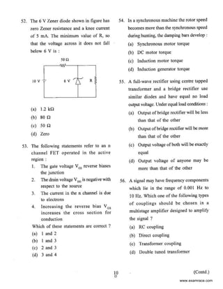
52. The 6 V Z~ner diode shown in figure has
zero Zener resistance and a knee current
of 5 rnA. The minimum value of R, so
that the voltage across it does not fall
below 6 Vis :
10 v- :-
(a) 1.2 kQ
(b) son
(c) son
(d) Zero
500
6V r:-' R
L
53. The following statements refer to an n
channel FET operated in the active
region :
I. The gate voltage Vos reverse biases
the junction
2. The drain voltage V00
is negative ~ith
respect to the source
3. The current in the n channel is due
to electrons
4. Increasing the reverse bias Vos
increases the cross section for
conduction
Which of these statements are correct ?
(a) I and 2
(b) l and 3
(c) 2 and 3
(d) 3 and 4
10
0
54. In a synchronous machine the rotor speed
becomes more than the synchronous speed
during hunting, the damping bars develop :
(a) Synchronous motor torque
(b) DC motor torque
(c) Induction motor torque
(d) Induction generator torque
55. A full-wave rectifier using centre tapped
transformer and a bridge rectifier usc
similar diodes and have equal no load
output voltage. Under equal load conditions :
(a) Output ofbridge rectifier will be less
than that of the other
(b) Output ofbridge n.'Ctifier will be more
than that of the other
(c) Output voltage ofboth will be exactly
equal
(d) Output voltage of anyone may be
more than that of the other
56. A signal may have frequency components
which lie in the range of 0.001 Hz to
I0 Hz. Which one of the following types
of couplings should be chosen in a
multistage amplifier designed to amplify
the signal ?
(a) RC coupling
(b) Direct coupIing
(c) Transformer coupling
(d) Double tuned transformer
(Contd.}
www.examrace.com
57. A feedback amplifier is designed with an
amplifier gain of -1000 and feedback of
13 =- 0.1. Ifthe amplifier had a gain change
of 20% due to temperature, the change in
gain of the feedback amplifier is :
(a) 10%
(b) 5%
(c) 0.2%
(d) 0.01%
58. A signal V.,sin (wt + ') is applied to an
amplifier whose gain A is independent of
frequency. The amplifier wiII preserve the
form of the input signal (though with a
delay) if the phase shift ' is :
(a) Constant
(b) Inversely proportional to frequency
(c) Proponional to frequency
(d) Proponional to the square of the
frequency
59. In any function · where microphone,
amplifier and speakers are used often one
would hear a humming sound, which
increases in volume gradually. This is due
to :
(a) Positive feedback between micro-
phone and speaker
(b) Negative feedback between micro-
phone and speaker
(c) Inadequate frequency response of
amplifier
(d) Noise pickup (50 Hz) from power
supply
II
0
60. The effect of current shunt feedback in
an amplifier is to :
(a) Increase the input resistance and
decrease the output resistance
(b) Increase both input and output
resistance
(c) Decrease both input and output
resistance
(d) Decrease the input resistance and
increase the output resistance
61. An amplifier circuit has an overall current
gain of -100 and an input resistance of
I0 kQ with a load resistance of I kO.
The overall voltage gain of the amplifier
is :
(a) 5 dB
(b) 10 dB
(c) 20 dB
(d) 40 dB
62. A 4-pole induction motor (main) and a
6-pole motor (auxiliary) are connected in
cumulative cascade. Frequency in the
secondary winding ofthe auxiliary motor
is observed to be I Hz. For a supply
frequency of50 Hz the speed ofthe cascade
set is :
(a) 1485 rpm
(b) 990 rpm
(c) 608 rpm
(d) 588 rpm
(Contd.)
www.examrace.com
63. An operational amplifier is connected in 67. Which of the following is correct for a
voltage follower configuration. Input given gated D-type flip flop ?
to this circuit is 3 sin I031tt. Compute the (a) The output is either SET or RESET
slew rate of operational amplifier. as soon as the D input goes HIGH
(a) 6n x I0-3 V/j.tsec
or LOW
(b) 31t X J0·3 Vf!lSeC
(b) The output complement follows the
(c) J.Sn x 10"3 V/j.isec
(d) 1t x 10·3 VIv.sec input when enabled
(c) Only one of the inputs can be HIGH
64. An OPAMP has a common mode gain of
at a time
0.01 and a differential mode gain of JQS
(d) The output toggles ifone ofthe inputsIts common mode rejection ratio would
be: is held HIGH
(a) 10"'
(b) J0-3 68. Latches constructed with NOR and NAND
(c) I03 gates tend to remain in the latched
(d) 107 condition due to which configuration
feature ?
65. An OPAMP has a slew rate of 5 V/~Js.
(a) Asynchronous operation
The largest sine wave output voltage
possible at a frequency of I MHz is : (b) Low input voltage
(a) 10 nV (c) Gate impedance
(b) 5 v (d) Cross coupling
(c) ~v 69. How is the speed-power product ofa logic
1t
family determined ?
(d) .l....v (a) The propagation delay in s is
21t
multiplied by the power dissipation
66. Consider the following statements : in mW
I. Astable multivibrator can be used for (b) The propagation delay in ms is
generating square wave multiplied by the power dissipation
2. Bistable multivibrator can be used in mW
for storing binary information (c) The propagation delay in ns is
Which ofthese statement(s) is/are correct? multiplied by the power dissipation
(a) I only
in mW
(b) 2 only
(d) The propagation delay in ns is
(c) Both 1 and 2
(d) Neither I nor 2
multiplied by the power dissipation
in W
12 (Contd.)
0
www.examrace.com
70. The integrated injection logic has higher
density of integration Lhan TTL because
it :
(a) Does not require transistors wilh high
current gain and hence they have ·
smaller geometry
(b) Uses bipolar transistor
(c) Does not require isolation diffusion
(d) Uses dynamic logic instead of static
logic
71. Consider the following statements :
A Darlington emitter-follower circuit js
sometimes used in output stage of a TfL
gate in order to :
I. Increase its 10
L
2. Reduce its 10 "
3. Increase speed of operation
4. Reduce power dissipation
Which ofthese statement(s) is/arecorrect ?
(a) I and 3
(b) 2 and 4
(c) 3 only
(d) I only
72. For the box shown the output D is true if
and only if a majority of the inputs are
true.
A--.1
Input 8- -+1 1---. D Output
The Boolean function for the output is :
(a) D =ABC + ABC + ABC
(b) D = ABC + ABC + ABC + ABC
(c) D =ABC + AB + AC + BC
(d) D = ABC + ABC + ABC + ABC
13
0
73. The Boolean expression :
F = A+B+C+A+B+C+
A+B+C + ABC
reduces to :
(a) A
(b) B
(c) C
(d) A+ B + C
74. When the output ofa tri-state shift register
is disabled, the output level is placed in
a:
(a) Float state
(b) Low state
(c) High impedance state
(d) Float state and a high impedance state
75. A programmable ROM has a decoder at
the input and :
(a) Both these blocks being fully
programmable
(b) Both these blocks being partially
programmable
(c) Only the latter block being pro-
grammable
(d) Only the former block being pro-
grammable
76. Synchronous counters eliminate the delay
problems encountered with asynchronous
(ripple) counter because the :
(a) Input clock pulses are applied only
to the first and the last stages
(b) Input clock pulses are applied only
to the last stage
(c) Jnput clock pulses are not used to
activate any of the counter stages
(d) Input clock pulses are applied simul-
taneously
(Contd.)
www.examrace.com
77. In a 8085 microprocessor system with
memory mapped 1/0, which of the
following is true ?
(a) Devices have 8-bit address line
(b) Devices are accessed using lN and
OUT instructions
(c) There can be maximum of256 input
devices and 256 output devices
(d) Arithmetic and logic operations can
be directly performed with the 110
data
78. Consider the following statements :
Arithmetic Logic Unit (ALU)
I. Perfom1s arithmetic operations
2. Performs comparisons
3. Communicates with I/0 devices
80. According to Flynn's classification, which
architecture is of only theoretical interest
and no practical system bas been developed
based on it ?
(a) Single Instruction Single Data (SISD)
(b) Single Instruction Multiple Data
(SIMD)
(c) Multiple Instruction Single Data
(MISD)
(d) Multiple Instruction Multiple Data
(MIMD)
81 . What is the content of accumulator of
8085 11P after the execution ofXRI FO H
instruction ?
(a) Only the upper nibble of accumulator
is complemented
(b) Only the lower nibble is complemented
4. Keeps watch on the system (c) Only the upper nibble is reset to zero
Which of these statements are correct ? (d) Only the lower nibble is reset to zero
(a) I, 2, 3 and 4
(b) I, 2 and 3 only
(c) I and 2 only
(d) 3 and 4 only
79. The 8085 programming manual says that
it takes seven T states to fetch and execute
the MOV instruction. If the system clock
has a frequency of2.5 MHz, how long is
an instruction cycle ?
(a) 2.8 s
(b) 2.5 ns
(c) 2.8 ns
(d) 2.8 11S
14
0
82. A software delay subroutine is written as
given below :
DELAY : MVl H, 255 D
MVI L, 255 D
LOOP: OCR L
JNZ LOOP
DCR H
JNZ LOOP
How many times OCR L instruction will
be executed ?
(a) 255
(b) 510
(c) 65025
(d) 65279
(Contd.)
www.examrace.com
83. The content of Accumulator are 7 OH.
Initially all flags are zero. What will be
values of Cy and S after executing
instruction RLC ?
(a) Cy = 0 and S = 0
(b) Cy = I and S = I
(c) Cy • I and S = 0
(d) Cy = 0 and S = I
84. The difference between 8085 instructions
RST n and PCHL is :
(a) RST n is equivalent to a sub-routine
call while PCHL is equivalent to
unconditional branch
(b) RST n uses direct addressing while
PCHL uses register indirect addressing
(c) RST n is a software interrupt while
PCHL simulates a hardware interrupt
(d) RST n resets the processor while
PCHL restarts the processor
85. The following program starts at location
OIOOH
LXI SP, OOFF
LXI H, 0701
MVJ A, 20H
SUB M
The content of accumulator when the
program counter reaches 0I07 H is :
(a) 20 H
(b) 02 H
(c) 00 H
(d) FF H
15
0
86. Find the content of the ac<:umulator after
the execution of the following program :
MVI A, FO H
ORJ FF H
XRI FO H
(a) OOH
(b) FOH
(c) OFH
(d) FFH
87. It is desired to multiply the numbers
OA H by OB H and store the result in the
accumulator. Tbe numbers are available
in registers B and C respectively. A pan
of the 8085 program for this purpose is
given below :
MVI A, OOH
Loop; ................
HLT END
The sequence of instruction to complete
the program would be :
(a) JNZ LOOP; ADD B; OCR C
(b) ADD B; JNZ LOOP; DCR C
(c) DCR C; JNZ LOOP; ADD B
(d) ADD B; DCR C; JNZ LOOP
88. Assume that the Accumulator and the
register C of 8085 microprocessor contain
respectively FO H and OF H initially. What
will be the content of Accumulator after
execution of instruction ADD C ?
(a) 00 H
(b) FF H
(c) EF H
(d) FE H
(Contd.)
www.examrace.com
89. Cycle-stealing mode of DMA operation
involves :
(a) OMA controller takes over the
address, data and control buses while
a block ofdata is transferred between
memory and an 110 device
(b) While the J.1P is executing a program
an interface circuit takes over control
ofthe address, data and control buses
when not in use by the J.1P
(c) Data transfer takes place between the
110 device and memory during every
alternate clock cycle
(d) The DMA controller waits for the
J.1P to finish execution ofthe program
and then takes over the bus.es
90. In a microprocessor based system, DMA
facility is required to increase the speed
of the data transfer between the :
(a) Microprocessor and the memory
(b) Microprocessor and the 110 devices
(c) Memory and the 110 devices
(d) Memory and register
91 . 110 mapped system identify their input/
output devices by giving them an :
(a) 8 bit port number
(b) 16 bit port number
(c) 8 bit buffer number
(d) 16 bit buffer number
92. A microprocessor based safety control
system installed in a nuclear power plant
must be stress tested under which of the
following conditions ?
16
0
I. Ageing due to radiation
2. Thermal stresses
3. Seismic vibration
4. Inadequate nuclear reactor coolant
(a) I and 2 only
(b) 2 and 4 only
(c) l, 2 and 3 only
(d) I, 2, 3 and 4
93. A carrier wave of frequency 2.5 GHz
amplitude is modulated with two
modulating frequencies equal to I kHz
and 2 kHz. The modulated wave will have
the total bandwidth :
(a) 6kHz
(b) 2kHz
(c) 4kHz
(d) 3 kHz
94. In a frequency modulation system,
maximum frequency deviation allowed is
1000 and modulating frequency is I kHz.
Determine modulation index J3.
(a) 2
(b) 2000
(c) I
(d) 1000
(Contd.)
www.examrace.com
95. In an Amplitude Modulated (AM) wave
with I00% modulation (m), the carrier is
suppressed. The percentage of power
saving wiII be :
(a) 100%
(b) 50%
(c) 25%
(d) 66.7%
96. The Nyquist sampling interval, for the
signal sinc(700t) + sinc(500t) is :
(a)
I
-sec
350
(b)
1t
- sec
350
(c)
I
- sec
700
(d)
1t
- sec
175
97. A I000-W carrier is amplitude-modulated
and has a side-band power of 300 W. The
depth of modulation is :
(a) 0.255
(b) 0.545
{c) 0.775
(d) 0.95
98. The value of the capacity reactance
obtainable from a reactance FET whose
g., is 12 ms when the gate-to-source
I
resistance is
9
of the reactance of the
gate-to-drain capacitor at ITequency 5 MHz
is :
(a) 650 Q
(b) 750 Q
(c) 775 n
(d) soo n
17
0
99. A thyristor has internal power dissipatio~
of 40 W and is operated at an ambient
temperature of20°C. 1fthermal resistance
is 1.6• C/W, the junction temperature is :
(a) 114" C
(b) t64•c
(c) 94° C
(d) 84° c
100. Consider the following statements :
I. A synchronous motor has no starting
torque but when started it always runs
at a fixed speed
2. A single-phase reluctance motor is
not self-starting even ifpaths for eddy
currents are provided in the rotor
3. A single-phase hysteresis motor is
self-starting
Which of these statement(s) isfare correct ?
(a) I, 2 and 3
(b) I only
(c) I and 2 only
(d) 2 and 3 only
101. Consider the following statements
regarding Thyristor :
I. It conducts when forward biased and
positive current flows through the gate
2. It conducts when forward biased and
negative current flows through the
gate
3. It commutates when reverse biased
and negative current flows through
the gate
4. ft eommutates when the gate current
is withdrawn
Which of these statement(s) isfare correct ?
(a) I, 2 and 3
(b) I and 2 only
(c) 2 and 3 only
(d) I only
(Contd.)
www.examrace.com
I02. The average output of a semi-converter
connected to a 120 V, SO Hz supply and
ti
. It
mng angle of 2 is :
(a) 54.02 V
(b) 56.02 v
(c) 108.04 V
(d) Zero
I03. Compute the ripple factor ofa single phase
full wave rectifier with load resistance
RL • 10 kQ. Forward bias dynamic
resistance of diodes used is I 00 Q. The
rms voltage across secondary winding is
330 v.
(a) 4.82
(b) 1.21
(c) 0.482
(d) 0.812
I04. A 3-phase semi-converter is feeding a
separately excited de motor at constant
field current. The motor can operate in
the following condition :
(a) Speed positive, torque positive
(b) Speed positive or negative, torque
positive
(c) Speed positive, torque positive or
negative
(d) Speed positive or negative, torque
positive or negative
18
0
105. A 3-phase converter feeds a pure resistance
load at a firing angle of a = 60°. The
average value of current flowing in the
load is I0 A. Ifa very large inductance is
connected in the load circuit, then the :
(a) Average value of current will remain
as lOA
(b) Average value ofcurrent will become
greater than I0 A
(c) Average value ofcurrent will become
less than I0 A
(d) Trend of variation of current cannot
be predicted unless the exact value
ofthe inductance connected is known
106. A PWM switching scheme is used with a
three phase inverter to :
(a) Reduce the total harmonic distortion
with modest filtering
(b) Minimize the load on the DC side
(c) Increase the life of the batteries
(d) Reduce low order harmonics and
increase high order harmonics
I 07. Consider the following statements :
Switched mode power supplies are
preferred over the continuous types,
because they are
I. Suitable for use in both ac and de
2. More efficient ·
3. Suitable for low-power circuits
4. Suitable for high-power circuits
Which of these statements are correct ?
(a) I and 2
(b) I and 3
(c) 2 and 3
(d) 3 and 4
(Contd.)
www.examrace.com
Directions :-
Each of the neKt THIRTEEN (JJ) items
consists of two statements, one labeled as the
'Statement (I)' and the other as ' Statement (II)'.
You are to eKamine these two statements
carefully and select the answers to these items
using the codes given below :
Codes:
(a) Both Statement (I) and Statement (11) are
individually true and Statement (II) is the
correct explanation of Statement (I)
(b) Both Statement (I) and Statement (II) are
individually true but Statement (II)
is NOT the correct explanation of
Statement (I)
(c) Statement (I) is true but Statement (II) is .
false
(d) Statement (I) is false but Statement (II) is
true
108. Statement (I)
Statement (ll)
Large power trans-
former testing under
full load current is not
possible.
Short circuit test of
transformer gives
indication of copper
loss.
I09. Statement (I)
Statement (11)
110. Statement (I)
Statement (II)
In large de motors
which drive reversing
rolls ofa steel mill and
in the geoerators which
supply them. large
fluctuations ofcurrents
cause higher voltages
being induced in the
coils located between
adjacent commutator
segments. This may
result in the so called
'flash-over' between
adjacent brushes,
causing a heavy short-
circuit.
To counteract the
possibilities ofa 'flash-
over', a 'compensating
winding', which is
embedded in the slots
on the pole-faces, is
connected in series
with the armature
winding, and which
supplies an mmf that
magnetizes in the
opposite direction to
that of the armature
mmf.
The direct-on-line
(DOL) starter is used
to start a small de
motor.
DOL starter limits
initial current drawn
by the armaturecircuit
(Contd.)
www.examrace.com
Ill. Statement (I)
Statement (II)
112. Statement (I)
Statement (II)
113. Statement (I)
Statement (II)
114. Statement (I)
Statement (U)
Tower to ground
impedance must be
kept high.
High impedance
produces high voltage
at the insulator disc.
No compensation is
needed in HVDC lines,
unlike EHV-AC system
where series and/or
shunt compensation is
required.
Chargi~ng current is
absent in HVDC
system.
In push-pull operation
one transistor conducts
only for negative half
cycle and other for
positive l1alf cycle.
Class-B power ampli-
fier is fixed in cutoff,
which gives non-
distorted output.
Program counter is a
register that contains
the address ofthe next
instruction to be
executed.
rR (Instruction Register)
is not accessible to
programmer.
20
0
115. Statement (I)
Statement (II)
116. Statement (I}
Statement (fl)
II7. Statement (I)
Statement (II)
I18. Statement (I)
Statement {II)
Partial memmy address
decoding can result in
simplified decoding
logic.
Partial decoding causes
many-to-one mapping
ofaddresses to memory
location.
In AM system the
modulation index
(0 < m < 1) should be
high.
The higher the value
of m the greater is the
power 10 the side
bands.
The total power in the
original carrier signal
is redistributed between
all the components of
the spectrum of the
frequency-modulated
signal.
The amplitude of the
carrier and the FMsignal
remain unchanged.
MOSFETs are intrin-
sically faster than bi-
polar devices.
MOSFETs have excess
minority carrier.
(Contd.)
www.examrace.com
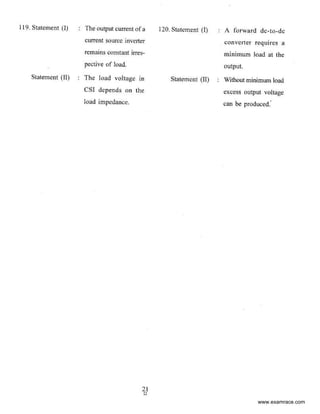
I19. Statement (I) The output current of a
current source invener
remains constant irres-
pectivc of load.
Statement (II) The load voltage m
CSI depends on the
load impedance.
21
0
120. Statement (I)
Statement (If)
A forward de-to-de
converter requires a
minimum load at the
output.
Without minimum load
excess output voltage
can be produced."
www.examrace.com
SPACE FOR ROUGH WORK
22
0
www.examrace.com
SPACE FOR ROUGH WORK
23
c
www.examrace.com
SPACE FOR ROUGH WORK
24
0
www.examrace.com

More Related Content

What's hot

196444650 ee-2257-control-system-lab-manual
196444650 ee-2257-control-system-lab-manual196444650 ee-2257-control-system-lab-manual
196444650 ee-2257-control-system-lab-manual
homeworkping3
 
ACモーターのスパイスモデルについて
ACモーターのスパイスモデルについてACモーターのスパイスモデルについて
ACモーターのスパイスモデルについて
Tsuyoshi Horigome
 
Automatic synch of gen
Automatic synch of genAutomatic synch of gen
Automatic synch of gen
michaeljmack
 
Design and Implementation of Two Stage Operational Amplifier
Design and Implementation of Two Stage Operational AmplifierDesign and Implementation of Two Stage Operational Amplifier
Design and Implementation of Two Stage Operational Amplifier
IRJET Journal
 
Concept Kit 3-Phase AC Motor Drive Simulation (LTspice Version)
Concept Kit 3-Phase AC Motor Drive Simulation (LTspice Version)Concept Kit 3-Phase AC Motor Drive Simulation (LTspice Version)
Concept Kit 3-Phase AC Motor Drive Simulation (LTspice Version)
Tsuyoshi Horigome
 
07
0707
DC Position Control System – Determination of Parameters and Significance on ...
DC Position Control System – Determination of Parameters and Significance on ...DC Position Control System – Determination of Parameters and Significance on ...
DC Position Control System – Determination of Parameters and Significance on ...
IDES Editor
 
Implementation of PWM Control of DC Split Converter Fed Switched Reluctance M...
Implementation of PWM Control of DC Split Converter Fed Switched Reluctance M...Implementation of PWM Control of DC Split Converter Fed Switched Reluctance M...
Implementation of PWM Control of DC Split Converter Fed Switched Reluctance M...
IJECEIAES
 
Device Modeling and Simulation of DC Motor using LTspice
Device Modeling and Simulation of  DC Motor using LTspiceDevice Modeling and Simulation of  DC Motor using LTspice
Device Modeling and Simulation of DC Motor using LTspice
Tsuyoshi Horigome
 
EEP301: Dc modular servo motor
EEP301: Dc modular servo motorEEP301: Dc modular servo motor
EEP301: Dc modular servo motor
Umang Gupta
 
Design of a Sample and Hold Circuit using Rail to Rail Low Voltage Compact Op...
Design of a Sample and Hold Circuit using Rail to Rail Low Voltage Compact Op...Design of a Sample and Hold Circuit using Rail to Rail Low Voltage Compact Op...
Design of a Sample and Hold Circuit using Rail to Rail Low Voltage Compact Op...
IJERA Editor
 
Gate question 2020
Gate question 2020Gate question 2020
Gate question 2020
Souvik Dutta
 
Power System Modeling and Simulation lab manual
Power System Modeling and Simulation lab manualPower System Modeling and Simulation lab manual
Power System Modeling and Simulation lab manual
DHEERAJ DHAKAR
 
Ece523 folded cascode design
Ece523 folded cascode designEce523 folded cascode design
Ece523 folded cascode design
Karthik Rathinavel
 
ECET 402 Entire Course NEW
ECET 402 Entire Course NEWECET 402 Entire Course NEW
ECET 402 Entire Course NEW
shyamuopuop
 
Tutorial on Distance and Over Current Protection
Tutorial on Distance and Over  Current ProtectionTutorial on Distance and Over  Current Protection
Tutorial on Distance and Over Current Protection
SARAVANAN A
 
Line Differential - Test report for Alstom make Micom P546 relay
Line Differential - Test report for Alstom make Micom P546 relayLine Differential - Test report for Alstom make Micom P546 relay
Line Differential - Test report for Alstom make Micom P546 relay
david roy
 
Quasi-resonant Flyback Converter Simulations with Saber - APEC 2016
Quasi-resonant Flyback Converter Simulations with Saber - APEC 2016Quasi-resonant Flyback Converter Simulations with Saber - APEC 2016
Quasi-resonant Flyback Converter Simulations with Saber - APEC 2016
Alan Courtay
 
Concept Kit 3-Phase AC Motor Drive Circuit Simulation (LTspice Version)
Concept Kit 3-Phase AC Motor Drive Circuit Simulation (LTspice Version)Concept Kit 3-Phase AC Motor Drive Circuit Simulation (LTspice Version)
Concept Kit 3-Phase AC Motor Drive Circuit Simulation (LTspice Version)
Tsuyoshi Horigome
 

What's hot (20)

196444650 ee-2257-control-system-lab-manual
196444650 ee-2257-control-system-lab-manual196444650 ee-2257-control-system-lab-manual
196444650 ee-2257-control-system-lab-manual
 
ACモーターのスパイスモデルについて
ACモーターのスパイスモデルについてACモーターのスパイスモデルについて
ACモーターのスパイスモデルについて
 
Automatic synch of gen
Automatic synch of genAutomatic synch of gen
Automatic synch of gen
 
Design and Implementation of Two Stage Operational Amplifier
Design and Implementation of Two Stage Operational AmplifierDesign and Implementation of Two Stage Operational Amplifier
Design and Implementation of Two Stage Operational Amplifier
 
Concept Kit 3-Phase AC Motor Drive Simulation (LTspice Version)
Concept Kit 3-Phase AC Motor Drive Simulation (LTspice Version)Concept Kit 3-Phase AC Motor Drive Simulation (LTspice Version)
Concept Kit 3-Phase AC Motor Drive Simulation (LTspice Version)
 
07
0707
07
 
DC Position Control System – Determination of Parameters and Significance on ...
DC Position Control System – Determination of Parameters and Significance on ...DC Position Control System – Determination of Parameters and Significance on ...
DC Position Control System – Determination of Parameters and Significance on ...
 
Implementation of PWM Control of DC Split Converter Fed Switched Reluctance M...
Implementation of PWM Control of DC Split Converter Fed Switched Reluctance M...Implementation of PWM Control of DC Split Converter Fed Switched Reluctance M...
Implementation of PWM Control of DC Split Converter Fed Switched Reluctance M...
 
Device Modeling and Simulation of DC Motor using LTspice
Device Modeling and Simulation of  DC Motor using LTspiceDevice Modeling and Simulation of  DC Motor using LTspice
Device Modeling and Simulation of DC Motor using LTspice
 
EEP301: Dc modular servo motor
EEP301: Dc modular servo motorEEP301: Dc modular servo motor
EEP301: Dc modular servo motor
 
Design of a Sample and Hold Circuit using Rail to Rail Low Voltage Compact Op...
Design of a Sample and Hold Circuit using Rail to Rail Low Voltage Compact Op...Design of a Sample and Hold Circuit using Rail to Rail Low Voltage Compact Op...
Design of a Sample and Hold Circuit using Rail to Rail Low Voltage Compact Op...
 
Gate question 2020
Gate question 2020Gate question 2020
Gate question 2020
 
Power System Modeling and Simulation lab manual
Power System Modeling and Simulation lab manualPower System Modeling and Simulation lab manual
Power System Modeling and Simulation lab manual
 
Ece523 folded cascode design
Ece523 folded cascode designEce523 folded cascode design
Ece523 folded cascode design
 
ECET 402 Entire Course NEW
ECET 402 Entire Course NEWECET 402 Entire Course NEW
ECET 402 Entire Course NEW
 
Tutorial on Distance and Over Current Protection
Tutorial on Distance and Over  Current ProtectionTutorial on Distance and Over  Current Protection
Tutorial on Distance and Over Current Protection
 
Line Differential - Test report for Alstom make Micom P546 relay
Line Differential - Test report for Alstom make Micom P546 relayLine Differential - Test report for Alstom make Micom P546 relay
Line Differential - Test report for Alstom make Micom P546 relay
 
Folded cascode1
Folded cascode1Folded cascode1
Folded cascode1
 
Quasi-resonant Flyback Converter Simulations with Saber - APEC 2016
Quasi-resonant Flyback Converter Simulations with Saber - APEC 2016Quasi-resonant Flyback Converter Simulations with Saber - APEC 2016
Quasi-resonant Flyback Converter Simulations with Saber - APEC 2016
 
Concept Kit 3-Phase AC Motor Drive Circuit Simulation (LTspice Version)
Concept Kit 3-Phase AC Motor Drive Circuit Simulation (LTspice Version)Concept Kit 3-Phase AC Motor Drive Circuit Simulation (LTspice Version)
Concept Kit 3-Phase AC Motor Drive Circuit Simulation (LTspice Version)
 

Viewers also liked

network theory part3
network theory part3network theory part3
network theory part3
Venugopala Rao P
 
network theory
network theory network theory
network theory
Venugopala Rao P
 
network theory
network theory network theory
network theory
Venugopala Rao P
 
IES MAINS 2017
IES MAINS 2017IES MAINS 2017
IES MAINS 2017
Soumya Sehgal
 
Principles of-communication-systems-by-herbert-taub-and-donald-l-schilling-2n...
Principles of-communication-systems-by-herbert-taub-and-donald-l-schilling-2n...Principles of-communication-systems-by-herbert-taub-and-donald-l-schilling-2n...
Principles of-communication-systems-by-herbert-taub-and-donald-l-schilling-2n...am
 
22 01 2014_03_23_31_eee_formula_sheet_final
22 01 2014_03_23_31_eee_formula_sheet_final22 01 2014_03_23_31_eee_formula_sheet_final
22 01 2014_03_23_31_eee_formula_sheet_final
vibhuti bansal
 

Viewers also liked (6)

network theory part3
network theory part3network theory part3
network theory part3
 
network theory
network theory network theory
network theory
 
network theory
network theory network theory
network theory
 
IES MAINS 2017
IES MAINS 2017IES MAINS 2017
IES MAINS 2017
 
Principles of-communication-systems-by-herbert-taub-and-donald-l-schilling-2n...
Principles of-communication-systems-by-herbert-taub-and-donald-l-schilling-2n...Principles of-communication-systems-by-herbert-taub-and-donald-l-schilling-2n...
Principles of-communication-systems-by-herbert-taub-and-donald-l-schilling-2n...
 
22 01 2014_03_23_31_eee_formula_sheet_final
22 01 2014_03_23_31_eee_formula_sheet_final22 01 2014_03_23_31_eee_formula_sheet_final
22 01 2014_03_23_31_eee_formula_sheet_final
 

Similar to Ies electrical-engineering-paper-ii-2013

CNE.pdf
CNE.pdfCNE.pdf
H09 Building Level Design
H09 Building Level DesignH09 Building Level Design
H09 Building Level Design
phase3-120A
 
Electrical machine lab
Electrical machine labElectrical machine lab
Electrical machine lab
DHEERAJ DHAKAR
 
Ies conventional-electrical-engineering-2012
Ies conventional-electrical-engineering-2012Ies conventional-electrical-engineering-2012
Ies conventional-electrical-engineering-2012
arunkumarmurugesan88
 
17415 d.c.machnes and transformer
17415   d.c.machnes and transformer17415   d.c.machnes and transformer
17415 d.c.machnes and transformer
soni_nits
 
Electrical Technology Jntu Model Paper{Www.Studentyogi.Com}
Electrical Technology Jntu Model Paper{Www.Studentyogi.Com}Electrical Technology Jntu Model Paper{Www.Studentyogi.Com}
Electrical Technology Jntu Model Paper{Www.Studentyogi.Com}
guest3f9c6b
 
E L E C T R I C A L T E C H N O L O G Y J N T U M O D E L P A P E R{Www
E L E C T R I C A L  T E C H N O L O G Y  J N T U  M O D E L  P A P E R{WwwE L E C T R I C A L  T E C H N O L O G Y  J N T U  M O D E L  P A P E R{Www
E L E C T R I C A L T E C H N O L O G Y J N T U M O D E L P A P E R{Wwwguest3f9c6b
 
Ee6351 ELECTRICAL DRIVES AND CONTROL
Ee6351 ELECTRICAL DRIVES AND CONTROLEe6351 ELECTRICAL DRIVES AND CONTROL
Ee6351 ELECTRICAL DRIVES AND CONTROL
BIBIN CHIDAMBARANATHAN
 
Ies electrical engineering - electrical machines
Ies   electrical engineering - electrical machinesIes   electrical engineering - electrical machines
Ies electrical engineering - electrical machines
Phaneendra Pgr
 
Building up voltage self excited shunt generator
Building up voltage self excited shunt  generator Building up voltage self excited shunt  generator
Building up voltage self excited shunt generator
Saif al-din ali
 
Electrical machines-lab-i-ee0209
Electrical machines-lab-i-ee0209Electrical machines-lab-i-ee0209
Electrical machines-lab-i-ee0209
Govt. College of Engineering, Kannur
 
Ee6503(r 13) qb-2013_regulation
Ee6503(r 13) qb-2013_regulationEe6503(r 13) qb-2013_regulation
Ee6503(r 13) qb-2013_regulation
Marimuthu Balasubramaniam
 
Supplementary material for the article: “Pseudo DC-link EV Home Charger with ...
Supplementary material for the article: “Pseudo DC-link EV Home Charger with ...Supplementary material for the article: “Pseudo DC-link EV Home Charger with ...
Supplementary material for the article: “Pseudo DC-link EV Home Charger with ...
Hamed Heydari
 
#SolarMOOC Random Problems from 2009 NABCEP STUDY GUIDE
#SolarMOOC Random Problems from 2009 NABCEP STUDY GUIDE#SolarMOOC Random Problems from 2009 NABCEP STUDY GUIDE
#SolarMOOC Random Problems from 2009 NABCEP STUDY GUIDE
solpowerpeople
 
Analysis of a novel seven phase uncontrolled rectifier system
Analysis of a novel seven phase uncontrolled rectifier systemAnalysis of a novel seven phase uncontrolled rectifier system
Analysis of a novel seven phase uncontrolled rectifier system
IRJET Journal
 
Emec 1 question
Emec 1 questionEmec 1 question
Emec 1 questionRavi Anand
 
electrical objective
electrical objectiveelectrical objective
electrical objective
Kalees Pandiyan
 
Objective Electrical Electronics Engineering Questions and Answers
Objective Electrical Electronics Engineering Questions and AnswersObjective Electrical Electronics Engineering Questions and Answers
Objective Electrical Electronics Engineering Questions and Answers
Mostafizur Rahman
 

Similar to Ies electrical-engineering-paper-ii-2013 (20)

CNE.pdf
CNE.pdfCNE.pdf
CNE.pdf
 
H09 Building Level Design
H09 Building Level DesignH09 Building Level Design
H09 Building Level Design
 
Electrical machine lab
Electrical machine labElectrical machine lab
Electrical machine lab
 
Ies conventional-electrical-engineering-2012
Ies conventional-electrical-engineering-2012Ies conventional-electrical-engineering-2012
Ies conventional-electrical-engineering-2012
 
17415 d.c.machnes and transformer
17415   d.c.machnes and transformer17415   d.c.machnes and transformer
17415 d.c.machnes and transformer
 
Electrical Technology Jntu Model Paper{Www.Studentyogi.Com}
Electrical Technology Jntu Model Paper{Www.Studentyogi.Com}Electrical Technology Jntu Model Paper{Www.Studentyogi.Com}
Electrical Technology Jntu Model Paper{Www.Studentyogi.Com}
 
E L E C T R I C A L T E C H N O L O G Y J N T U M O D E L P A P E R{Www
E L E C T R I C A L  T E C H N O L O G Y  J N T U  M O D E L  P A P E R{WwwE L E C T R I C A L  T E C H N O L O G Y  J N T U  M O D E L  P A P E R{Www
E L E C T R I C A L T E C H N O L O G Y J N T U M O D E L P A P E R{Www
 
Ee6351 ELECTRICAL DRIVES AND CONTROL
Ee6351 ELECTRICAL DRIVES AND CONTROLEe6351 ELECTRICAL DRIVES AND CONTROL
Ee6351 ELECTRICAL DRIVES AND CONTROL
 
Ies electrical engineering - electrical machines
Ies   electrical engineering - electrical machinesIes   electrical engineering - electrical machines
Ies electrical engineering - electrical machines
 
Building up voltage self excited shunt generator
Building up voltage self excited shunt  generator Building up voltage self excited shunt  generator
Building up voltage self excited shunt generator
 
Electrical machines-lab-i-ee0209
Electrical machines-lab-i-ee0209Electrical machines-lab-i-ee0209
Electrical machines-lab-i-ee0209
 
Neeraj kumar
Neeraj kumarNeeraj kumar
Neeraj kumar
 
Neeraj kumar
Neeraj kumarNeeraj kumar
Neeraj kumar
 
Ee6503(r 13) qb-2013_regulation
Ee6503(r 13) qb-2013_regulationEe6503(r 13) qb-2013_regulation
Ee6503(r 13) qb-2013_regulation
 
Supplementary material for the article: “Pseudo DC-link EV Home Charger with ...
Supplementary material for the article: “Pseudo DC-link EV Home Charger with ...Supplementary material for the article: “Pseudo DC-link EV Home Charger with ...
Supplementary material for the article: “Pseudo DC-link EV Home Charger with ...
 
#SolarMOOC Random Problems from 2009 NABCEP STUDY GUIDE
#SolarMOOC Random Problems from 2009 NABCEP STUDY GUIDE#SolarMOOC Random Problems from 2009 NABCEP STUDY GUIDE
#SolarMOOC Random Problems from 2009 NABCEP STUDY GUIDE
 
Analysis of a novel seven phase uncontrolled rectifier system
Analysis of a novel seven phase uncontrolled rectifier systemAnalysis of a novel seven phase uncontrolled rectifier system
Analysis of a novel seven phase uncontrolled rectifier system
 
Emec 1 question
Emec 1 questionEmec 1 question
Emec 1 question
 
electrical objective
electrical objectiveelectrical objective
electrical objective
 
Objective Electrical Electronics Engineering Questions and Answers
Objective Electrical Electronics Engineering Questions and AnswersObjective Electrical Electronics Engineering Questions and Answers
Objective Electrical Electronics Engineering Questions and Answers
 

More from Venugopala Rao P

How to prepare for ies with eee
How to prepare for ies with eeeHow to prepare for ies with eee
How to prepare for ies with eee
Venugopala Rao P
 
How to get registered in salesforce
How to get registered in salesforceHow to get registered in salesforce
How to get registered in salesforce
Venugopala Rao P
 
Tsnpdcl
Tsnpdcl Tsnpdcl
TPSC Ae exam qp_07112015
TPSC Ae exam qp_07112015TPSC Ae exam qp_07112015
TPSC Ae exam qp_07112015
Venugopala Rao P
 
Gate ee previous year papers 1992 2010
Gate ee previous year papers 1992   2010Gate ee previous year papers 1992   2010
Gate ee previous year papers 1992 2010
Venugopala Rao P
 
Question booklet series_a_ies_2014
Question booklet series_a_ies_2014Question booklet series_a_ies_2014
Question booklet series_a_ies_2014
Venugopala Rao P
 
Proof
ProofProof
Ies electrical-engineering-paper-ii-2012
Ies electrical-engineering-paper-ii-2012Ies electrical-engineering-paper-ii-2012
Ies electrical-engineering-paper-ii-2012
Venugopala Rao P
 
Ies electrical-engineering-paper-i-2013
Ies electrical-engineering-paper-i-2013Ies electrical-engineering-paper-i-2013
Ies electrical-engineering-paper-i-2013
Venugopala Rao P
 
Ies electrical-engineering-paper-i-2012
Ies electrical-engineering-paper-i-2012Ies electrical-engineering-paper-i-2012
Ies electrical-engineering-paper-i-2012
Venugopala Rao P
 
Ies electrical-engineering-paper-2-2008
Ies electrical-engineering-paper-2-2008Ies electrical-engineering-paper-2-2008
Ies electrical-engineering-paper-2-2008
Venugopala Rao P
 
Ies electrical-engineering-paper-2-2006
Ies electrical-engineering-paper-2-2006Ies electrical-engineering-paper-2-2006
Ies electrical-engineering-paper-2-2006
Venugopala Rao P
 
Ies electrical-engineering-paper-2-2005
Ies electrical-engineering-paper-2-2005Ies electrical-engineering-paper-2-2005
Ies electrical-engineering-paper-2-2005
Venugopala Rao P
 
Ies electrical-engineering-paper-2-2004
Ies electrical-engineering-paper-2-2004Ies electrical-engineering-paper-2-2004
Ies electrical-engineering-paper-2-2004
Venugopala Rao P
 
Ies electrical-engineering-paper-2-2003
Ies electrical-engineering-paper-2-2003Ies electrical-engineering-paper-2-2003
Ies electrical-engineering-paper-2-2003
Venugopala Rao P
 
Ies electrical-engineering-paper-2-2002
Ies electrical-engineering-paper-2-2002Ies electrical-engineering-paper-2-2002
Ies electrical-engineering-paper-2-2002
Venugopala Rao P
 
Ies electrical-engineering-paper-2-2000
Ies electrical-engineering-paper-2-2000Ies electrical-engineering-paper-2-2000
Ies electrical-engineering-paper-2-2000
Venugopala Rao P
 
Ies electrical-engineering-paper-2-2001
Ies electrical-engineering-paper-2-2001Ies electrical-engineering-paper-2-2001
Ies electrical-engineering-paper-2-2001
Venugopala Rao P
 
Ies electrical-engineering-paper-2-1999
Ies electrical-engineering-paper-2-1999Ies electrical-engineering-paper-2-1999
Ies electrical-engineering-paper-2-1999
Venugopala Rao P
 
Ies electrical-engineering-paper-2-1998
Ies electrical-engineering-paper-2-1998Ies electrical-engineering-paper-2-1998
Ies electrical-engineering-paper-2-1998
Venugopala Rao P
 

More from Venugopala Rao P (20)

How to prepare for ies with eee
How to prepare for ies with eeeHow to prepare for ies with eee
How to prepare for ies with eee
 
How to get registered in salesforce
How to get registered in salesforceHow to get registered in salesforce
How to get registered in salesforce
 
Tsnpdcl
Tsnpdcl Tsnpdcl
Tsnpdcl
 
TPSC Ae exam qp_07112015
TPSC Ae exam qp_07112015TPSC Ae exam qp_07112015
TPSC Ae exam qp_07112015
 
Gate ee previous year papers 1992 2010
Gate ee previous year papers 1992   2010Gate ee previous year papers 1992   2010
Gate ee previous year papers 1992 2010
 
Question booklet series_a_ies_2014
Question booklet series_a_ies_2014Question booklet series_a_ies_2014
Question booklet series_a_ies_2014
 
Proof
ProofProof
Proof
 
Ies electrical-engineering-paper-ii-2012
Ies electrical-engineering-paper-ii-2012Ies electrical-engineering-paper-ii-2012
Ies electrical-engineering-paper-ii-2012
 
Ies electrical-engineering-paper-i-2013
Ies electrical-engineering-paper-i-2013Ies electrical-engineering-paper-i-2013
Ies electrical-engineering-paper-i-2013
 
Ies electrical-engineering-paper-i-2012
Ies electrical-engineering-paper-i-2012Ies electrical-engineering-paper-i-2012
Ies electrical-engineering-paper-i-2012
 
Ies electrical-engineering-paper-2-2008
Ies electrical-engineering-paper-2-2008Ies electrical-engineering-paper-2-2008
Ies electrical-engineering-paper-2-2008
 
Ies electrical-engineering-paper-2-2006
Ies electrical-engineering-paper-2-2006Ies electrical-engineering-paper-2-2006
Ies electrical-engineering-paper-2-2006
 
Ies electrical-engineering-paper-2-2005
Ies electrical-engineering-paper-2-2005Ies electrical-engineering-paper-2-2005
Ies electrical-engineering-paper-2-2005
 
Ies electrical-engineering-paper-2-2004
Ies electrical-engineering-paper-2-2004Ies electrical-engineering-paper-2-2004
Ies electrical-engineering-paper-2-2004
 
Ies electrical-engineering-paper-2-2003
Ies electrical-engineering-paper-2-2003Ies electrical-engineering-paper-2-2003
Ies electrical-engineering-paper-2-2003
 
Ies electrical-engineering-paper-2-2002
Ies electrical-engineering-paper-2-2002Ies electrical-engineering-paper-2-2002
Ies electrical-engineering-paper-2-2002
 
Ies electrical-engineering-paper-2-2000
Ies electrical-engineering-paper-2-2000Ies electrical-engineering-paper-2-2000
Ies electrical-engineering-paper-2-2000
 
Ies electrical-engineering-paper-2-2001
Ies electrical-engineering-paper-2-2001Ies electrical-engineering-paper-2-2001
Ies electrical-engineering-paper-2-2001
 
Ies electrical-engineering-paper-2-1999
Ies electrical-engineering-paper-2-1999Ies electrical-engineering-paper-2-1999
Ies electrical-engineering-paper-2-1999
 
Ies electrical-engineering-paper-2-1998
Ies electrical-engineering-paper-2-1998Ies electrical-engineering-paper-2-1998
Ies electrical-engineering-paper-2-1998
 

Recently uploaded

Immunizing Image Classifiers Against Localized Adversary Attacks
Immunizing Image Classifiers Against Localized Adversary AttacksImmunizing Image Classifiers Against Localized Adversary Attacks
Immunizing Image Classifiers Against Localized Adversary Attacks
gerogepatton
 
road safety engineering r s e unit 3.pdf
road safety engineering  r s e unit 3.pdfroad safety engineering  r s e unit 3.pdf
road safety engineering r s e unit 3.pdf
VENKATESHvenky89705
 
Student information management system project report ii.pdf
Student information management system project report ii.pdfStudent information management system project report ii.pdf
Student information management system project report ii.pdf
Kamal Acharya
 
ML for identifying fraud using open blockchain data.pptx
ML for identifying fraud using open blockchain data.pptxML for identifying fraud using open blockchain data.pptx
ML for identifying fraud using open blockchain data.pptx
Vijay Dialani, PhD
 
Nuclear Power Economics and Structuring 2024
Nuclear Power Economics and Structuring 2024Nuclear Power Economics and Structuring 2024
Nuclear Power Economics and Structuring 2024
Massimo Talia
 
Fundamentals of Electric Drives and its applications.pptx
Fundamentals of Electric Drives and its applications.pptxFundamentals of Electric Drives and its applications.pptx
Fundamentals of Electric Drives and its applications.pptx
manasideore6
 
Pile Foundation by Venkatesh Taduvai (Sub Geotechnical Engineering II)-conver...
Pile Foundation by Venkatesh Taduvai (Sub Geotechnical Engineering II)-conver...Pile Foundation by Venkatesh Taduvai (Sub Geotechnical Engineering II)-conver...
Pile Foundation by Venkatesh Taduvai (Sub Geotechnical Engineering II)-conver...
AJAYKUMARPUND1
 
一比一原版(IIT毕业证)伊利诺伊理工大学毕业证成绩单专业办理
一比一原版(IIT毕业证)伊利诺伊理工大学毕业证成绩单专业办理一比一原版(IIT毕业证)伊利诺伊理工大学毕业证成绩单专业办理
一比一原版(IIT毕业证)伊利诺伊理工大学毕业证成绩单专业办理
zwunae
 
Planning Of Procurement o different goods and services
Planning Of Procurement o different goods and servicesPlanning Of Procurement o different goods and services
Planning Of Procurement o different goods and services
JoytuBarua2
 
RAT: Retrieval Augmented Thoughts Elicit Context-Aware Reasoning in Long-Hori...
RAT: Retrieval Augmented Thoughts Elicit Context-Aware Reasoning in Long-Hori...RAT: Retrieval Augmented Thoughts Elicit Context-Aware Reasoning in Long-Hori...
RAT: Retrieval Augmented Thoughts Elicit Context-Aware Reasoning in Long-Hori...
thanhdowork
 
Design and Analysis of Algorithms-DP,Backtracking,Graphs,B&B
Design and Analysis of Algorithms-DP,Backtracking,Graphs,B&BDesign and Analysis of Algorithms-DP,Backtracking,Graphs,B&B
Design and Analysis of Algorithms-DP,Backtracking,Graphs,B&B
Sreedhar Chowdam
 
CFD Simulation of By-pass Flow in a HRSG module by R&R Consult.pptx
CFD Simulation of By-pass Flow in a HRSG module by R&R Consult.pptxCFD Simulation of By-pass Flow in a HRSG module by R&R Consult.pptx
CFD Simulation of By-pass Flow in a HRSG module by R&R Consult.pptx
R&R Consult
 
Cosmetic shop management system project report.pdf
Cosmetic shop management system project report.pdfCosmetic shop management system project report.pdf
Cosmetic shop management system project report.pdf
Kamal Acharya
 
Sachpazis:Terzaghi Bearing Capacity Estimation in simple terms with Calculati...
Sachpazis:Terzaghi Bearing Capacity Estimation in simple terms with Calculati...Sachpazis:Terzaghi Bearing Capacity Estimation in simple terms with Calculati...
Sachpazis:Terzaghi Bearing Capacity Estimation in simple terms with Calculati...
Dr.Costas Sachpazis
 
Hierarchical Digital Twin of a Naval Power System
Hierarchical Digital Twin of a Naval Power SystemHierarchical Digital Twin of a Naval Power System
Hierarchical Digital Twin of a Naval Power System
Kerry Sado
 
Top 10 Oil and Gas Projects in Saudi Arabia 2024.pdf
Top 10 Oil and Gas Projects in Saudi Arabia 2024.pdfTop 10 Oil and Gas Projects in Saudi Arabia 2024.pdf
Top 10 Oil and Gas Projects in Saudi Arabia 2024.pdf
Teleport Manpower Consultant
 
H.Seo, ICLR 2024, MLILAB, KAIST AI.pdf
H.Seo,  ICLR 2024, MLILAB,  KAIST AI.pdfH.Seo,  ICLR 2024, MLILAB,  KAIST AI.pdf
H.Seo, ICLR 2024, MLILAB, KAIST AI.pdf
MLILAB
 
space technology lecture notes on satellite
space technology lecture notes on satellitespace technology lecture notes on satellite
space technology lecture notes on satellite
ongomchris
 
Runway Orientation Based on the Wind Rose Diagram.pptx
Runway Orientation Based on the Wind Rose Diagram.pptxRunway Orientation Based on the Wind Rose Diagram.pptx
Runway Orientation Based on the Wind Rose Diagram.pptx
SupreethSP4
 
Final project report on grocery store management system..pdf
Final project report on grocery store management system..pdfFinal project report on grocery store management system..pdf
Final project report on grocery store management system..pdf
Kamal Acharya
 

Recently uploaded (20)

Immunizing Image Classifiers Against Localized Adversary Attacks
Immunizing Image Classifiers Against Localized Adversary AttacksImmunizing Image Classifiers Against Localized Adversary Attacks
Immunizing Image Classifiers Against Localized Adversary Attacks
 
road safety engineering r s e unit 3.pdf
road safety engineering  r s e unit 3.pdfroad safety engineering  r s e unit 3.pdf
road safety engineering r s e unit 3.pdf
 
Student information management system project report ii.pdf
Student information management system project report ii.pdfStudent information management system project report ii.pdf
Student information management system project report ii.pdf
 
ML for identifying fraud using open blockchain data.pptx
ML for identifying fraud using open blockchain data.pptxML for identifying fraud using open blockchain data.pptx
ML for identifying fraud using open blockchain data.pptx
 
Nuclear Power Economics and Structuring 2024
Nuclear Power Economics and Structuring 2024Nuclear Power Economics and Structuring 2024
Nuclear Power Economics and Structuring 2024
 
Fundamentals of Electric Drives and its applications.pptx
Fundamentals of Electric Drives and its applications.pptxFundamentals of Electric Drives and its applications.pptx
Fundamentals of Electric Drives and its applications.pptx
 
Pile Foundation by Venkatesh Taduvai (Sub Geotechnical Engineering II)-conver...
Pile Foundation by Venkatesh Taduvai (Sub Geotechnical Engineering II)-conver...Pile Foundation by Venkatesh Taduvai (Sub Geotechnical Engineering II)-conver...
Pile Foundation by Venkatesh Taduvai (Sub Geotechnical Engineering II)-conver...
 
一比一原版(IIT毕业证)伊利诺伊理工大学毕业证成绩单专业办理
一比一原版(IIT毕业证)伊利诺伊理工大学毕业证成绩单专业办理一比一原版(IIT毕业证)伊利诺伊理工大学毕业证成绩单专业办理
一比一原版(IIT毕业证)伊利诺伊理工大学毕业证成绩单专业办理
 
Planning Of Procurement o different goods and services
Planning Of Procurement o different goods and servicesPlanning Of Procurement o different goods and services
Planning Of Procurement o different goods and services
 
RAT: Retrieval Augmented Thoughts Elicit Context-Aware Reasoning in Long-Hori...
RAT: Retrieval Augmented Thoughts Elicit Context-Aware Reasoning in Long-Hori...RAT: Retrieval Augmented Thoughts Elicit Context-Aware Reasoning in Long-Hori...
RAT: Retrieval Augmented Thoughts Elicit Context-Aware Reasoning in Long-Hori...
 
Design and Analysis of Algorithms-DP,Backtracking,Graphs,B&B
Design and Analysis of Algorithms-DP,Backtracking,Graphs,B&BDesign and Analysis of Algorithms-DP,Backtracking,Graphs,B&B
Design and Analysis of Algorithms-DP,Backtracking,Graphs,B&B
 
CFD Simulation of By-pass Flow in a HRSG module by R&R Consult.pptx
CFD Simulation of By-pass Flow in a HRSG module by R&R Consult.pptxCFD Simulation of By-pass Flow in a HRSG module by R&R Consult.pptx
CFD Simulation of By-pass Flow in a HRSG module by R&R Consult.pptx
 
Cosmetic shop management system project report.pdf
Cosmetic shop management system project report.pdfCosmetic shop management system project report.pdf
Cosmetic shop management system project report.pdf
 
Sachpazis:Terzaghi Bearing Capacity Estimation in simple terms with Calculati...
Sachpazis:Terzaghi Bearing Capacity Estimation in simple terms with Calculati...Sachpazis:Terzaghi Bearing Capacity Estimation in simple terms with Calculati...
Sachpazis:Terzaghi Bearing Capacity Estimation in simple terms with Calculati...
 
Hierarchical Digital Twin of a Naval Power System
Hierarchical Digital Twin of a Naval Power SystemHierarchical Digital Twin of a Naval Power System
Hierarchical Digital Twin of a Naval Power System
 
Top 10 Oil and Gas Projects in Saudi Arabia 2024.pdf
Top 10 Oil and Gas Projects in Saudi Arabia 2024.pdfTop 10 Oil and Gas Projects in Saudi Arabia 2024.pdf
Top 10 Oil and Gas Projects in Saudi Arabia 2024.pdf
 
H.Seo, ICLR 2024, MLILAB, KAIST AI.pdf
H.Seo,  ICLR 2024, MLILAB,  KAIST AI.pdfH.Seo,  ICLR 2024, MLILAB,  KAIST AI.pdf
H.Seo, ICLR 2024, MLILAB, KAIST AI.pdf
 
space technology lecture notes on satellite
space technology lecture notes on satellitespace technology lecture notes on satellite
space technology lecture notes on satellite
 
Runway Orientation Based on the Wind Rose Diagram.pptx
Runway Orientation Based on the Wind Rose Diagram.pptxRunway Orientation Based on the Wind Rose Diagram.pptx
Runway Orientation Based on the Wind Rose Diagram.pptx
 
Final project report on grocery store management system..pdf
Final project report on grocery store management system..pdfFinal project report on grocery store management system..pdf
Final project report on grocery store management system..pdf
 

Ies electrical-engineering-paper-ii-2013

  • 1. Engineeiing Ser~ces Examination-20f ~ [oo NOT OPEN THIS TEST BOOKLET UNTIL YOU ARE ASKED TO DO SO) T.B.C. : B-FRF- M- DDB Serial No. l l TEST BOOKLET ELECTRICAL ENGINEERING PAPER- II Test Booklet Series A[Time Allowed : '/Wo Hours ( Maximum Marks : 200J I. 2. 3. 4. s. 6. 7. INSTRUCTIONS IMMEDIATELY AFTER THE COMMENCEMENT OF T HE EXAMINATION, YOU SHOULD CHECK THAT THIS TEST BOOKLET DOES NOT HAVE ANY UNPRINTED OR TORN OR MISS£NG PAGES OR ITEMS, ETC. IF SO, GET IT REPLACED BY A COMPLETE TEST BOOKLET. PLEASE NOTE THAT IT IS THE CANDIDATE'S RESPONSIBILITY TO ENCODt: AND FILL IN THE ROLL NUMBER AND TEST BOOKLET SERIES COm ; A, B, C OR D CAREFULLY AND WITHOUT ANY OMISSION Oil DISCREPANCY AT THE APPROPRIATE PLACES IN T HE OMR ANSWER SHEET. ANY OMISSION I DISCREPANCY WILL RENDER THE ANSWER SHEET LIABLE FOR REJECTION. You have to enter vour Roll Number on the Test Booklet in [ ] the Box provided a longside. DO NOT write anything else on the Test Bookie!. ' - - - -- - - - - - ----' This Test Booklet contains 120 items (questions). Each item comprises four responses (answers). You will select the response which you want to mark on the Answer Sheet. In case, you feel that there is more than one correct response. mark the response which you consider the best. In any case, choose ONLY ONE response for each item. You have to mark your responses ONLY on the separate Answer Sheet provided. See directions in the Answer Sheet. All items carry equal marks. Before you proceed to mark in tho Answer Sheet the response to various items in the Test Booklet, you have to fill in some particulars in the Answer Sheet as per instructions seot to you with your Admission Certificate. 8. After you have completed fill ing in all your responses on the Answer Sheet and the examination has concluded, you should hand over to the lnvigilator only the Answer Shut. You are permitted to take away with you the Test Booklet. 9. Sheets for rough work are append.ed in the Test Booklet at the end. 10. Penalty for wrong answers : THERE WILL BE PENALTY FOR WRONG ANSWERS MARKED BY A CANDIDATE. (i) There are four alternatives for the answer to every question. For each question for which a wrong answer has been give n by the candidate. one-third of the marks assigned tO that question will be deducted as penalty. {ii) If a candidate gives more than one answer, it will be treated as wrong answer even if one of the given answers happens to be correct and there will be same penalty as above to that question. {iii) If a question is left blank, i.e. no answer is given by the candidate, there will be no penalty for that question. ( DO NOT OPEN THIS TEST BOOKLET UNTIL YOU ARE AS KED TO DO SO) www.examrace.com
  • 2. I. When a transformer is first energized, the transient current during first few cycles is : (a) Less than full load current (b) Equal to full load current (c) Equal to no load current (d) Much higher than full load current 2. For power transformers of larger ratings, the tappings are located in the middle portion of the winding to : (a) Increase the break-down strength of the winding insulation (b) Enable better cooling ofthe windings (c) Enable better distribution of inter- tum voltage (d) Reduce the mechanical forces affecting tbe windings during short- circuits 3. Tappings are normally provided on the high voltage winding ofa transformer only, because : (a) lt has larger number of turns which allows smoother variation of voltage (b) It has to handle low currents (c) It is easily accessible physically (d) It has larger number of turns, has to handle low currents and is also easily accessible physically 4. Short circuit test is performed on a transformer with a certain impressed voltage at rated frequency. If the short circuit test is now performed with the same magnitude of impressed voltage, but at a frequency higher than the rated frequency, then tbe magnitude of current : (a) And power-factor will both increase (b) Will decrease but the power factor will increase (c) Will increase, but power factor will decrease (d) And power factor will both decrease 2 0 5. The impedance of a 6/Y, II 000 V/400 V, transformer of capacity I 00 kVA, on its name plate data base is (0.02 +j0.07) p.u. The ohmic impedance p.u. phase referred to the prirhary (II 000 V) side is : (a) (0.02 + j 0.07) Q {b) (0.55 + j 1.925) Q (c) (42 + j 147) Q (d) (72.6 + j 254.1) Q 6. A 2000 kVA, single-phase transformer is in circuit continuously. For 8 hours in a day, the load is 160 kW at 0.8 pf. For 6 hours, the load is 80 kW at unity pf and for the period remaining out of 24 hours, it runs on no-load. If the full-load copper losses are 3.02 kW, the total copper losses in 24 hours are : (a) 35.62 kW (b) 24.16 kW (c) 11.46 kW (d) 38.40 kW 7. A 50 kVA transformer has a core loss of 500 W and full-load core loss of 900 W. The load at which the efficiency is maximum is: (a) 27.45 kVA (b) 37.75 kVA (c) 45.5 kVA (d) 47.5 kVA 8. For a two-winding power transformer, with the effects of the no-load current being neglected, the 'Voltage Regulation' can be zero at load, when the load power- factor is : (a) Lagging only (b) Leading only (c) Either lagging or leading, depending upon power rating of tbe transformer (d) Unity (Contd.) www.examrace.com
  • 3. 9. The ratio of primary/secondary voltages is 2 : I. The saving in terms of weight of copper required if an autotransformer is used instead ofa two-winding transformer will be : (a) 95% (b) 66.7% (c) 50% (d) 33.3% I0. Consider the following statements concerning the utility of mesh-connected tertiary winding,s in star-star transformers : I. It is used to suppress harmonic voltages 2. It is used to allow flow ofearth fault current for operation of protective devices 3. It facilitates supply of single-phase loads 4. It provides low-reactance paths for zero sequence currents Which of these statements are correct ? (a) 1, 2, 3 and 4 (b) I. 2 and 3 only (c) I, 2 and 4 only (d) 3 and 4 only II . The most essential condition for parallel operation of two 1-41 transformers is that they should have the same : (a) kVA rating (b) Percentage impedance (c) Polarity (d) Voltage ratio 3 0 12. Two single-phase 100 kVA transformers, each having different leakage impedances are connected in parallel. When a load of 150 kVA at 0.8 power factor lagging is applied : (a) Both transformers will operate at power factor more than 0.8 lagging (b) Both transformers will operate at power factor less than 0.8 lagging (c) One of the transformers will operate at power factor more than 0.8 lagging and other will operate at power factor less than 0.8 lagging (d) Both transformers will operate at identical power factors 13. A triangular mmf wave is produced in the air-gap of an electric machine. Such a wave is produced by : (a) Stator of an induction machine (b) Rotor of a synchronous machine (c) Stator of a de machine (d) Rotor of a de machine 14. At 1200 rpm the induced emf of a de machine is 200 V. For an armature current of 15 A the electromagnetic torque produced would be : (a) 23.8 N-m (b) 238 N-m (c) 2000 N-m (d) 3000 N-m (Contd.) www.examrace.com
  • 4. 15. A 4-pole lap wound de generator has a developed power of P watt and voltage of E volt. Two adjacent brushes of the machine are removed as they are worn out. If the machine operates with the remaining brushes, the developed voltage and power that can be obtained frQm the machine are : (a) E and P (b) E/2 and P/2 (c) E and P/4 (d) E and P/2 16. A 6-pole de armature has simplex lap- connected 720 conductors, 3 turns per coil and 4 coil-sides per slot. Determine the number of slots in the armature and state whether equalizers can be employed or not. (a) 60 slots and Not Possible (b) 30 slots and Possible (c) 60 slots and Possible (d) 30 slots and Not Possible 17. Oetennine the flux per pole for 6-po1e de machine having 240 wave connected conductors, which generates an open circuit voltage of 500 volt, which is running at 1000 rpm. (a) 0.129 Wb (b) 0.021 Wb (c) 0.042 Wb (d) 7 mWb 4 0 18. 19. 20. Consider the following statements : The armature reaction mmf in a de machine is : I. Stationary with respect to the field poles 2. Rotating withrespect to the field poles 3. Rotating with respect to the arn1ature Which of these statements are correct ? (a) I, 2 and 3 (b) l and 2 only (c) 1 and 3 only (d) 2 and 3 only In case ofde motor, maximum mechanical power is developed when back emf equals : (a) The applied voltage (b) Half the applied voltage (c) One third of the applied voltage (d) Double the applied voltage The induced emfofa de machine running at 750 rpm is ~20 V. The percentage increase in field flux for generating an induced emf of 250 V at 700 rpm would be : (a) 7% (b) 11.25% (c) 21.7% (d) 42.4% (Contd.) www.examrace.com
  • 5. 21 . 1be speed ofa sepamtely excited de motor is varied by varying the armature voltage in the range zero to base speed and by varying the field current above the base speed. It is suitable for constan1 : (a) Torque drive at all speeds (b) Power drive at all speeds (c) Torque drive till base speed and constant power drive beyond base speed (d) Power drive till base speed and constant torque drive beyond base speed 22. A de shunt motor is required to drive a constant power load at rated speed while drawing rated armature current. Neglecting satumtion and all machine losses, if both the terminal voltage and the field current of the machine are halved then : (a) The speed becomes 2 pu but armature current remains at I pu (b) The speed remains at I pu but armature current becomes 2 pu (c) Both speed and armature current become 2 pu (d) Both speed and armature current remain at I pu 23. The de series motor is best suited for traction work, because : (a) Torque is proportional to the square of armature current and speed is inversely proportional to torque (b) Torque is proportional to the square of armature current and speed is directly proportional to torque (c) Both torque and speed are proportional to the square ofarmature current (d) Torque is proportional to armature current and speed is inversely proportional to torque 5 0 24. A 3-phase synchronous motor with constant excitation is driving a certain load drawing electric power from inftnite bus at leading power factor. If the shaft load decreases : (a) The power angle decreases while power factor increases (b) The power angle increases while power factor decreases (c) Both power angle and power factor increase (d) Both power angle and power factor decrease 25. The maximum power delivered by 1500 kW. 3-phase, star-connected, 4 kV, 48 pole 50 Hz synchronous motor, with synchronous reactance of 4 n per phase and unity power factor : (a) 4271.2 kW .(b) 3505 kW (c) 1206.1 kW (d) 2078 kW 26. Consider the following statements regarding synchronous machines : I. When a synchronous motor is over- excited, its back emf is greater than the supply voltage 2. When a synchronous motor is over- excited, its power factor is leading 3. Synchronous motor is used as capacitor where load is so large that construction of a static capacitor is impractical Which of these statements are correct ? (a) I and 2 only (b) I and 3 only (c) 2 and 3 only (d) I, 2 and 3 (Contd.) www.examrace.com
  • 6. 27. In TV transmission, picture signal is amplitude modulated and sound signal is frequency modulated. This is done because : (a) It is not possible to frequency modulate the picture signal (b) Band width requirement is minimized (c) Sound signal is more susceptible to noise than picture signal (d) Synchronization of picture frames becomes easier 28. A system has a receiver noise resistance of 50 Q. It is connected to an antenna with an output resistance of 50 Q. The noise figure of the system is : (a) (b) 2 (c) 50 (d) 10I 29. The power gain of an antenna using paraboloid reflector is directly proportional to : (a) Mouth diameter (b) Wavelength (c) Aperture ratio (d) Square of aperture ratio 6 0 30. A binary channel with capacity of 36 kbitsl sec is available for PCM voice transmission. If signal is band limited to 3.2 kHz, then the appropriate values of quantizing level L and the sampling frequency respectively are : (a) 32 and 3.6 kHz (b) 64 and 7.2 kHz (c) 64 and 3.6 kHz (d) 32 and 7.2 kHz 31. A 8-bit AID convertor is used over a span ofzero to 2.56 V. l11e binary representation of 1.0 V signal is : (a) Oil 001 00 (b) 011 100 01 (c) 101 001 Ol (d) 101 000 10 32. RF carrier 10 kV at I MHz is amplitude modulated and modulation index is 0.6. Peak voltage of the signal is : (a) 600 kV (b) 1200 kV (c) 6 kV (d) 10 kV 33. Output data ratio of a 8-bit PCM-TDM system sampling 24 voice channels, comparing these using 11-law at the rate of 8 kHz and with a I frame alignment word, is : (a) 1.2 X I06 bits/sec (b) 1.4 )( l06 bits/sec (c) 1.6 X I06 bits/sec (d) 1.8 X l 06 bits/sec (Contd.) www.examrace.com
  • 7. 34. 24 voice channels are sampled uniformly at a rate of 8 kHz and then time division multiplexed. Tite sampling process uses flat-top samples with 1 llS duration. The multiplexing operation includes provision ofsynchronization by adding an exua pulse of I llS duration. The spacing between successive pulses of the multiplexed signal is : (a) 4 llS (b) 6 llS (c) 7.2 llS (d) 8.4 llS 35. A signal is passed through a LPF with cut-off frequency I 0 kHz. The minimum sampling frequency is : (a) 5kHz (b) 10kHz (c) 20kHz (d) 30kHz 36. The main advantage of time division multiplexing (TDM) over frequency division multiplexing (FDM) is that it : (a) Requires less bandwidth (b) Requires less power (c) Requires simple circuitry (d) Provide better signal-to-noise ratio 37. The advantage of hydro-electric power station over thermal power station is : (a) The initial cost of hydro-electric power station is low (b) The operating cost of hydro-electric power station is low (c) Hydro-electric power station can supply the power throughout the year (d) Hydro-electric power station can be constructed at the place where the energy is required 7 0 38. The incremental cost characteristics oftwo generators delivering 200 MW are as follows : dF. - 2 = l.6+0.02P2dP2 For economic operation the generation P1 and P2 should be : (a) 100 MW and 100 MW (b) 80 MW and 120 MW (c) 200 MW and 100 MW (d) 120 MW and 80 MW 39. No load test was conducted on a three phase induction motor at different input voltages and the input power obtained was plotted against the input voltage. The inter- section of the extrapolated curve on the Y-axis, would give : (a) Rated core loss (b) Windage and friction loss (c) Rated copper loss (d) Rated core loss and Windage and friction loss 40.. A power generating station has a maximum demand of lOOO MW. The annual load factor is 75% and plant capacity factor is 60%. Calculate the reserve capacity. (a) 250 MW (b) 500 MW (c) 750 MW (d) 1250 MW (Contd.) www.examrace.com
  • 8. 41. In order to have lower cost of power generation : (a) The load factor and diversity factor should be low (b) The load factor and diversity factor should be high (c) The load factor should be low but diversity factor should be high (d) The load factor should be high but diversity factor should be low 42. Consider the following statements : The calculation performed using short line approximate model instead ofnominal-n model for a medium length transmission line delivering lagging load at a given receiving end voltage always results in higher : I. Sending end current 2. Sending end power 3. Regulation 4. Efficiency Which of these statements are correct ? (a) I and 2 only (b) 2 and 3 only (c) I, 2 and 4 (d) l, 3 and 4 8 D 43. The locus of constant received power is a circle of radius : 44. Consider the following statements regarding convergence of the Newton- Raphson procedure : I. It does not converge to a root when the second differential coefficient changes sign 2. It is preferred when the graph of (X) is nearly horizontal where it crosses the X-axis 3. It is used to solve algebraic and transcendental equations Which of these statements are correct ? (a) I, 2 and 3 (b) 1 and 2 only (c) 2 and 3 only (d) I and 3 only (Contd.) www.examrace.com
  • 9. 45. The Positive, Negative and Zero sequence per unit impedances of two generators connected in parallel are X1 = 0.12, X2 = 0.096 and ~ = 0.036 pu. For a L-G fault at generator terminals (with I pu voltage) the positive sequence current will be : (a) 7.936 pu (b) 11.936 pu (c) 10.936 pu (d) 8.936 pu 46. A 50 MVA, II kV, 3-phase generator has a stored energy of 400 M.J. Its inertia constant is : (a) 4 (b) 8 (c) 2 (d) 16 47. The steady state stability limit of a synchronous machine connected to infinite bus is 2.2 pu. Infinite bus voltage is I pu and synchronous machine voltage is 1.1 pu. The transfer reactance between generator and infinite bus is : (a) j 0.5 (b) -j 0.5 (c) j 1.0 (d) -j 1.0 48. Two identical synchronous machines having same inertia constant are connected in parallel and swinging together. The effective inertia constant is 4 MJ/MVA. Then each machine has an inertia constant of: (a) 2 MJ/MVA (b) 4 MJ/MVA (c) 8 MJ/MVA (d) 16 MJIMVA 49. A large ac generator supplying power to an infinite bus is suddenly short-circuited at its terminals. Assuming the prime-mover input and the voltage behind the transient reactance to remain constant immediately after the fault, the acceleration of the generator rotor is : (a) Inversely proportional to the moment of inertia of the machine (b) Inversely proportional to the square of the voItage (c) Directly proportional to the square of the short-circuit current (d) Directly proportional to the short- circuit power 50. The regions of operation of a MOSFET to work as a linear resistor and linear amplifier are : (a) Cut-off and saturation respectively (b) Triode and Cut-off respectively (c) Triode and saturation respectively (d) Saturation and Triode respectively 51. In a BJT, leo = Iceo = 2 1-1A. Given u = 0.99, the value of lcEO is : (a) 2 I-lA (b) 99 I-lA (c) 198 1-1A (d) 200 1-1A (Contd.) www.examrace.com
  • 10. 52. The 6 V Z~ner diode shown in figure has zero Zener resistance and a knee current of 5 rnA. The minimum value of R, so that the voltage across it does not fall below 6 Vis : 10 v- :- (a) 1.2 kQ (b) son (c) son (d) Zero 500 6V r:-' R L 53. The following statements refer to an n channel FET operated in the active region : I. The gate voltage Vos reverse biases the junction 2. The drain voltage V00 is negative ~ith respect to the source 3. The current in the n channel is due to electrons 4. Increasing the reverse bias Vos increases the cross section for conduction Which of these statements are correct ? (a) I and 2 (b) l and 3 (c) 2 and 3 (d) 3 and 4 10 0 54. In a synchronous machine the rotor speed becomes more than the synchronous speed during hunting, the damping bars develop : (a) Synchronous motor torque (b) DC motor torque (c) Induction motor torque (d) Induction generator torque 55. A full-wave rectifier using centre tapped transformer and a bridge rectifier usc similar diodes and have equal no load output voltage. Under equal load conditions : (a) Output ofbridge rectifier will be less than that of the other (b) Output ofbridge n.'Ctifier will be more than that of the other (c) Output voltage ofboth will be exactly equal (d) Output voltage of anyone may be more than that of the other 56. A signal may have frequency components which lie in the range of 0.001 Hz to I0 Hz. Which one of the following types of couplings should be chosen in a multistage amplifier designed to amplify the signal ? (a) RC coupling (b) Direct coupIing (c) Transformer coupling (d) Double tuned transformer (Contd.} www.examrace.com
  • 11. 57. A feedback amplifier is designed with an amplifier gain of -1000 and feedback of 13 =- 0.1. Ifthe amplifier had a gain change of 20% due to temperature, the change in gain of the feedback amplifier is : (a) 10% (b) 5% (c) 0.2% (d) 0.01% 58. A signal V.,sin (wt + ') is applied to an amplifier whose gain A is independent of frequency. The amplifier wiII preserve the form of the input signal (though with a delay) if the phase shift ' is : (a) Constant (b) Inversely proportional to frequency (c) Proponional to frequency (d) Proponional to the square of the frequency 59. In any function · where microphone, amplifier and speakers are used often one would hear a humming sound, which increases in volume gradually. This is due to : (a) Positive feedback between micro- phone and speaker (b) Negative feedback between micro- phone and speaker (c) Inadequate frequency response of amplifier (d) Noise pickup (50 Hz) from power supply II 0 60. The effect of current shunt feedback in an amplifier is to : (a) Increase the input resistance and decrease the output resistance (b) Increase both input and output resistance (c) Decrease both input and output resistance (d) Decrease the input resistance and increase the output resistance 61. An amplifier circuit has an overall current gain of -100 and an input resistance of I0 kQ with a load resistance of I kO. The overall voltage gain of the amplifier is : (a) 5 dB (b) 10 dB (c) 20 dB (d) 40 dB 62. A 4-pole induction motor (main) and a 6-pole motor (auxiliary) are connected in cumulative cascade. Frequency in the secondary winding ofthe auxiliary motor is observed to be I Hz. For a supply frequency of50 Hz the speed ofthe cascade set is : (a) 1485 rpm (b) 990 rpm (c) 608 rpm (d) 588 rpm (Contd.) www.examrace.com
  • 12. 63. An operational amplifier is connected in 67. Which of the following is correct for a voltage follower configuration. Input given gated D-type flip flop ? to this circuit is 3 sin I031tt. Compute the (a) The output is either SET or RESET slew rate of operational amplifier. as soon as the D input goes HIGH (a) 6n x I0-3 V/j.tsec or LOW (b) 31t X J0·3 Vf!lSeC (b) The output complement follows the (c) J.Sn x 10"3 V/j.isec (d) 1t x 10·3 VIv.sec input when enabled (c) Only one of the inputs can be HIGH 64. An OPAMP has a common mode gain of at a time 0.01 and a differential mode gain of JQS (d) The output toggles ifone ofthe inputsIts common mode rejection ratio would be: is held HIGH (a) 10"' (b) J0-3 68. Latches constructed with NOR and NAND (c) I03 gates tend to remain in the latched (d) 107 condition due to which configuration feature ? 65. An OPAMP has a slew rate of 5 V/~Js. (a) Asynchronous operation The largest sine wave output voltage possible at a frequency of I MHz is : (b) Low input voltage (a) 10 nV (c) Gate impedance (b) 5 v (d) Cross coupling (c) ~v 69. How is the speed-power product ofa logic 1t family determined ? (d) .l....v (a) The propagation delay in s is 21t multiplied by the power dissipation 66. Consider the following statements : in mW I. Astable multivibrator can be used for (b) The propagation delay in ms is generating square wave multiplied by the power dissipation 2. Bistable multivibrator can be used in mW for storing binary information (c) The propagation delay in ns is Which ofthese statement(s) is/are correct? multiplied by the power dissipation (a) I only in mW (b) 2 only (d) The propagation delay in ns is (c) Both 1 and 2 (d) Neither I nor 2 multiplied by the power dissipation in W 12 (Contd.) 0 www.examrace.com
  • 13. 70. The integrated injection logic has higher density of integration Lhan TTL because it : (a) Does not require transistors wilh high current gain and hence they have · smaller geometry (b) Uses bipolar transistor (c) Does not require isolation diffusion (d) Uses dynamic logic instead of static logic 71. Consider the following statements : A Darlington emitter-follower circuit js sometimes used in output stage of a TfL gate in order to : I. Increase its 10 L 2. Reduce its 10 " 3. Increase speed of operation 4. Reduce power dissipation Which ofthese statement(s) is/arecorrect ? (a) I and 3 (b) 2 and 4 (c) 3 only (d) I only 72. For the box shown the output D is true if and only if a majority of the inputs are true. A--.1 Input 8- -+1 1---. D Output The Boolean function for the output is : (a) D =ABC + ABC + ABC (b) D = ABC + ABC + ABC + ABC (c) D =ABC + AB + AC + BC (d) D = ABC + ABC + ABC + ABC 13 0 73. The Boolean expression : F = A+B+C+A+B+C+ A+B+C + ABC reduces to : (a) A (b) B (c) C (d) A+ B + C 74. When the output ofa tri-state shift register is disabled, the output level is placed in a: (a) Float state (b) Low state (c) High impedance state (d) Float state and a high impedance state 75. A programmable ROM has a decoder at the input and : (a) Both these blocks being fully programmable (b) Both these blocks being partially programmable (c) Only the latter block being pro- grammable (d) Only the former block being pro- grammable 76. Synchronous counters eliminate the delay problems encountered with asynchronous (ripple) counter because the : (a) Input clock pulses are applied only to the first and the last stages (b) Input clock pulses are applied only to the last stage (c) Jnput clock pulses are not used to activate any of the counter stages (d) Input clock pulses are applied simul- taneously (Contd.) www.examrace.com
  • 14. 77. In a 8085 microprocessor system with memory mapped 1/0, which of the following is true ? (a) Devices have 8-bit address line (b) Devices are accessed using lN and OUT instructions (c) There can be maximum of256 input devices and 256 output devices (d) Arithmetic and logic operations can be directly performed with the 110 data 78. Consider the following statements : Arithmetic Logic Unit (ALU) I. Perfom1s arithmetic operations 2. Performs comparisons 3. Communicates with I/0 devices 80. According to Flynn's classification, which architecture is of only theoretical interest and no practical system bas been developed based on it ? (a) Single Instruction Single Data (SISD) (b) Single Instruction Multiple Data (SIMD) (c) Multiple Instruction Single Data (MISD) (d) Multiple Instruction Multiple Data (MIMD) 81 . What is the content of accumulator of 8085 11P after the execution ofXRI FO H instruction ? (a) Only the upper nibble of accumulator is complemented (b) Only the lower nibble is complemented 4. Keeps watch on the system (c) Only the upper nibble is reset to zero Which of these statements are correct ? (d) Only the lower nibble is reset to zero (a) I, 2, 3 and 4 (b) I, 2 and 3 only (c) I and 2 only (d) 3 and 4 only 79. The 8085 programming manual says that it takes seven T states to fetch and execute the MOV instruction. If the system clock has a frequency of2.5 MHz, how long is an instruction cycle ? (a) 2.8 s (b) 2.5 ns (c) 2.8 ns (d) 2.8 11S 14 0 82. A software delay subroutine is written as given below : DELAY : MVl H, 255 D MVI L, 255 D LOOP: OCR L JNZ LOOP DCR H JNZ LOOP How many times OCR L instruction will be executed ? (a) 255 (b) 510 (c) 65025 (d) 65279 (Contd.) www.examrace.com
  • 15. 83. The content of Accumulator are 7 OH. Initially all flags are zero. What will be values of Cy and S after executing instruction RLC ? (a) Cy = 0 and S = 0 (b) Cy = I and S = I (c) Cy • I and S = 0 (d) Cy = 0 and S = I 84. The difference between 8085 instructions RST n and PCHL is : (a) RST n is equivalent to a sub-routine call while PCHL is equivalent to unconditional branch (b) RST n uses direct addressing while PCHL uses register indirect addressing (c) RST n is a software interrupt while PCHL simulates a hardware interrupt (d) RST n resets the processor while PCHL restarts the processor 85. The following program starts at location OIOOH LXI SP, OOFF LXI H, 0701 MVJ A, 20H SUB M The content of accumulator when the program counter reaches 0I07 H is : (a) 20 H (b) 02 H (c) 00 H (d) FF H 15 0 86. Find the content of the ac<:umulator after the execution of the following program : MVI A, FO H ORJ FF H XRI FO H (a) OOH (b) FOH (c) OFH (d) FFH 87. It is desired to multiply the numbers OA H by OB H and store the result in the accumulator. Tbe numbers are available in registers B and C respectively. A pan of the 8085 program for this purpose is given below : MVI A, OOH Loop; ................ HLT END The sequence of instruction to complete the program would be : (a) JNZ LOOP; ADD B; OCR C (b) ADD B; JNZ LOOP; DCR C (c) DCR C; JNZ LOOP; ADD B (d) ADD B; DCR C; JNZ LOOP 88. Assume that the Accumulator and the register C of 8085 microprocessor contain respectively FO H and OF H initially. What will be the content of Accumulator after execution of instruction ADD C ? (a) 00 H (b) FF H (c) EF H (d) FE H (Contd.) www.examrace.com
  • 16. 89. Cycle-stealing mode of DMA operation involves : (a) OMA controller takes over the address, data and control buses while a block ofdata is transferred between memory and an 110 device (b) While the J.1P is executing a program an interface circuit takes over control ofthe address, data and control buses when not in use by the J.1P (c) Data transfer takes place between the 110 device and memory during every alternate clock cycle (d) The DMA controller waits for the J.1P to finish execution ofthe program and then takes over the bus.es 90. In a microprocessor based system, DMA facility is required to increase the speed of the data transfer between the : (a) Microprocessor and the memory (b) Microprocessor and the 110 devices (c) Memory and the 110 devices (d) Memory and register 91 . 110 mapped system identify their input/ output devices by giving them an : (a) 8 bit port number (b) 16 bit port number (c) 8 bit buffer number (d) 16 bit buffer number 92. A microprocessor based safety control system installed in a nuclear power plant must be stress tested under which of the following conditions ? 16 0 I. Ageing due to radiation 2. Thermal stresses 3. Seismic vibration 4. Inadequate nuclear reactor coolant (a) I and 2 only (b) 2 and 4 only (c) l, 2 and 3 only (d) I, 2, 3 and 4 93. A carrier wave of frequency 2.5 GHz amplitude is modulated with two modulating frequencies equal to I kHz and 2 kHz. The modulated wave will have the total bandwidth : (a) 6kHz (b) 2kHz (c) 4kHz (d) 3 kHz 94. In a frequency modulation system, maximum frequency deviation allowed is 1000 and modulating frequency is I kHz. Determine modulation index J3. (a) 2 (b) 2000 (c) I (d) 1000 (Contd.) www.examrace.com
  • 17. 95. In an Amplitude Modulated (AM) wave with I00% modulation (m), the carrier is suppressed. The percentage of power saving wiII be : (a) 100% (b) 50% (c) 25% (d) 66.7% 96. The Nyquist sampling interval, for the signal sinc(700t) + sinc(500t) is : (a) I -sec 350 (b) 1t - sec 350 (c) I - sec 700 (d) 1t - sec 175 97. A I000-W carrier is amplitude-modulated and has a side-band power of 300 W. The depth of modulation is : (a) 0.255 (b) 0.545 {c) 0.775 (d) 0.95 98. The value of the capacity reactance obtainable from a reactance FET whose g., is 12 ms when the gate-to-source I resistance is 9 of the reactance of the gate-to-drain capacitor at ITequency 5 MHz is : (a) 650 Q (b) 750 Q (c) 775 n (d) soo n 17 0 99. A thyristor has internal power dissipatio~ of 40 W and is operated at an ambient temperature of20°C. 1fthermal resistance is 1.6• C/W, the junction temperature is : (a) 114" C (b) t64•c (c) 94° C (d) 84° c 100. Consider the following statements : I. A synchronous motor has no starting torque but when started it always runs at a fixed speed 2. A single-phase reluctance motor is not self-starting even ifpaths for eddy currents are provided in the rotor 3. A single-phase hysteresis motor is self-starting Which of these statement(s) isfare correct ? (a) I, 2 and 3 (b) I only (c) I and 2 only (d) 2 and 3 only 101. Consider the following statements regarding Thyristor : I. It conducts when forward biased and positive current flows through the gate 2. It conducts when forward biased and negative current flows through the gate 3. It commutates when reverse biased and negative current flows through the gate 4. ft eommutates when the gate current is withdrawn Which of these statement(s) isfare correct ? (a) I, 2 and 3 (b) I and 2 only (c) 2 and 3 only (d) I only (Contd.) www.examrace.com
  • 18. I02. The average output of a semi-converter connected to a 120 V, SO Hz supply and ti . It mng angle of 2 is : (a) 54.02 V (b) 56.02 v (c) 108.04 V (d) Zero I03. Compute the ripple factor ofa single phase full wave rectifier with load resistance RL • 10 kQ. Forward bias dynamic resistance of diodes used is I 00 Q. The rms voltage across secondary winding is 330 v. (a) 4.82 (b) 1.21 (c) 0.482 (d) 0.812 I04. A 3-phase semi-converter is feeding a separately excited de motor at constant field current. The motor can operate in the following condition : (a) Speed positive, torque positive (b) Speed positive or negative, torque positive (c) Speed positive, torque positive or negative (d) Speed positive or negative, torque positive or negative 18 0 105. A 3-phase converter feeds a pure resistance load at a firing angle of a = 60°. The average value of current flowing in the load is I0 A. Ifa very large inductance is connected in the load circuit, then the : (a) Average value of current will remain as lOA (b) Average value ofcurrent will become greater than I0 A (c) Average value ofcurrent will become less than I0 A (d) Trend of variation of current cannot be predicted unless the exact value ofthe inductance connected is known 106. A PWM switching scheme is used with a three phase inverter to : (a) Reduce the total harmonic distortion with modest filtering (b) Minimize the load on the DC side (c) Increase the life of the batteries (d) Reduce low order harmonics and increase high order harmonics I 07. Consider the following statements : Switched mode power supplies are preferred over the continuous types, because they are I. Suitable for use in both ac and de 2. More efficient · 3. Suitable for low-power circuits 4. Suitable for high-power circuits Which of these statements are correct ? (a) I and 2 (b) I and 3 (c) 2 and 3 (d) 3 and 4 (Contd.) www.examrace.com
  • 19. Directions :- Each of the neKt THIRTEEN (JJ) items consists of two statements, one labeled as the 'Statement (I)' and the other as ' Statement (II)'. You are to eKamine these two statements carefully and select the answers to these items using the codes given below : Codes: (a) Both Statement (I) and Statement (11) are individually true and Statement (II) is the correct explanation of Statement (I) (b) Both Statement (I) and Statement (II) are individually true but Statement (II) is NOT the correct explanation of Statement (I) (c) Statement (I) is true but Statement (II) is . false (d) Statement (I) is false but Statement (II) is true 108. Statement (I) Statement (ll) Large power trans- former testing under full load current is not possible. Short circuit test of transformer gives indication of copper loss. I09. Statement (I) Statement (11) 110. Statement (I) Statement (II) In large de motors which drive reversing rolls ofa steel mill and in the geoerators which supply them. large fluctuations ofcurrents cause higher voltages being induced in the coils located between adjacent commutator segments. This may result in the so called 'flash-over' between adjacent brushes, causing a heavy short- circuit. To counteract the possibilities ofa 'flash- over', a 'compensating winding', which is embedded in the slots on the pole-faces, is connected in series with the armature winding, and which supplies an mmf that magnetizes in the opposite direction to that of the armature mmf. The direct-on-line (DOL) starter is used to start a small de motor. DOL starter limits initial current drawn by the armaturecircuit (Contd.) www.examrace.com
  • 20. Ill. Statement (I) Statement (II) 112. Statement (I) Statement (II) 113. Statement (I) Statement (II) 114. Statement (I) Statement (U) Tower to ground impedance must be kept high. High impedance produces high voltage at the insulator disc. No compensation is needed in HVDC lines, unlike EHV-AC system where series and/or shunt compensation is required. Chargi~ng current is absent in HVDC system. In push-pull operation one transistor conducts only for negative half cycle and other for positive l1alf cycle. Class-B power ampli- fier is fixed in cutoff, which gives non- distorted output. Program counter is a register that contains the address ofthe next instruction to be executed. rR (Instruction Register) is not accessible to programmer. 20 0 115. Statement (I) Statement (II) 116. Statement (I} Statement (fl) II7. Statement (I) Statement (II) I18. Statement (I) Statement {II) Partial memmy address decoding can result in simplified decoding logic. Partial decoding causes many-to-one mapping ofaddresses to memory location. In AM system the modulation index (0 < m < 1) should be high. The higher the value of m the greater is the power 10 the side bands. The total power in the original carrier signal is redistributed between all the components of the spectrum of the frequency-modulated signal. The amplitude of the carrier and the FMsignal remain unchanged. MOSFETs are intrin- sically faster than bi- polar devices. MOSFETs have excess minority carrier. (Contd.) www.examrace.com
  • 21. I19. Statement (I) The output current of a current source invener remains constant irres- pectivc of load. Statement (II) The load voltage m CSI depends on the load impedance. 21 0 120. Statement (I) Statement (If) A forward de-to-de converter requires a minimum load at the output. Without minimum load excess output voltage can be produced." www.examrace.com
  • 22. SPACE FOR ROUGH WORK 22 0 www.examrace.com
  • 23. SPACE FOR ROUGH WORK 23 c www.examrace.com
  • 24. SPACE FOR ROUGH WORK 24 0 www.examrace.com