This document discusses output capacitor selection for low voltage, high current power supplies used in applications like microprocessors. It derives an equation to calculate the minimum number of capacitors needed to meet transient voltage regulation requirements during load current steps. Different capacitor types are compared based on this calculation, including electrolytic, tantalum, ceramic, and polymer capacitors. Simulation and experimental results are presented to verify the theoretical analysis. The analysis shows that the minimum capacitors required depends on factors like equivalent series resistance, capacitance, current step size, and whether the system frequency is higher or lower than the capacitor's zero frequency. This methodology allows engineers to optimize capacitor selection for cost and performance.
Harmonic comparisons of various PWM techniques for basic MLISaquib Maqsood
Cascaded inverters are ideal for connecting renewable energy sources with an AC grid, because of the need for separate dc sources, which is the case in applications such as photovoltaic or fuel cells. The inverter could be controlled to either regulate the power factor of the current drawn from the source or the bus voltage of the electrical system where the inverter was connected. The modulation techniques are crucial in operating any inverter at desired conditions. In this work different PWM techniques are implemented for five level cascaded multilevel inverter and THD variation is analyzed.
Two leg three-phase inverters (FSTPIs) have been proposed to be used in low-power; low-cost applications because of the reduced number of semiconductor devices, and space vector pulse width modulation (SVPWM) techniques have also been introduced to control FSTPIs. However, high-performance controllers are needed to implement complicated SVPWM algorithms, which limit their low-cost applications. To simplify algorithms and reduce the cost of implementation, an equivalent scalar method for SVPWM of FSTPIs is proposed. SVPWM for FSTPIs is actually a sine PWM by modulating two sine waves of 600 phase difference with a triangle wave, but in this method third harmonics doesn’t eliminated. So as to eliminate the third harmonics we have to compose a high frequency sine wave to on existing sine waves. So such a special sine PWM can be used to control FSTPIs. The Mathematical and simulation results demonstrate the validity of the proposed method.
http://www.mathworks.com/matlabcentral/fileexchange/authors/126814
Analysis Approach for Five Phase Two-Level Voltage Source Inverter with PWM T...ijsrd.com
this paper gives idea of comparison of five phase two-level voltage inverter (FPTLVSI) without filter circuit and control scheme and FPTLVSI with filter circuit and PWM control scheme for induction motor drive. The paper demonstrates using mat lab simulations about comparison in term of harmonics analysis for different firing angles and find best angle suitable for output with minimum harmonics for FPTLVSI without filter circuit and control scheme and harmonics analysis of FPTLVSI with filter and PWM control scheme. This paper suggests simulation of comparison of harmonics point of view five phase two-level voltage inverter (FPTLVSI) without filter circuit and control scheme and with filter circuit and PWM control scheme for induction motor drive.
The Parallel RLC Circuit is the exact opposite to the series circuit we looked at in the previous tutorial although some of the previous concepts and equations still apply.
Computer Science
Active and Programmable Networks
Active safety systems
Ad Hoc & Sensor Network
Ad hoc networks for pervasive communications
Adaptive, autonomic and context-aware computing
Advance Computing technology and their application
Advanced Computing Architectures and New Programming Models
Advanced control and measurement
Aeronautical Engineering,
Agent-based middleware
Alert applications
Automotive, marine and aero-space control and all other control applications
Autonomic and self-managing middleware
Autonomous vehicle
Biochemistry
Bioinformatics
BioTechnology(Chemistry, Mathematics, Statistics, Geology)
Broadband and intelligent networks
Broadband wireless technologies
CAD/CAM/CAT/CIM
Call admission and flow/congestion control
Capacity planning and dimensioning
Changing Access to Patient Information
Channel capacity modelling and analysis
Civil Engineering,
Cloud Computing and Applications
Collaborative applications
Communication application
Communication architectures for pervasive computing
Communication systems
Computational intelligence
Computer and microprocessor-based control
Computer Architecture and Embedded Systems
Computer Business
Computer Sciences and Applications
Computer Vision
Computer-based information systems in health care
Computing Ethics
Computing Practices & Applications
Congestion and/or Flow Control
Content Distribution
Context-awareness and middleware
Creativity in Internet management and retailing
Cross-layer design and Physical layer based issue
Cryptography
Data Base Management
Data fusion
Data Mining
Data retrieval
Data Storage Management
Decision analysis methods
Decision making
Digital Economy and Digital Divide
Digital signal processing theory
Distributed Sensor Networks
Drives automation
Drug Design,
Drug Development
DSP implementation
E-Business
E-Commerce
E-Government
Electronic transceiver device for Retail Marketing Industries
Electronics Engineering,
Embeded Computer System
Emerging advances in business and its applications
Emerging signal processing areas
Enabling technologies for pervasive systems
Energy-efficient and green pervasive computing
Environmental Engineering,
Estimation and identification techniques
Evaluation techniques for middleware solutions
Event-based, publish/subscribe, and message-oriented middleware
Evolutionary computing and intelligent systems
Expert approaches
Facilities planning and management
Flexible manufacturing systems
Formal methods and tools for designing
Fuzzy algorithms
Fuzzy logics
GPS and location-based app
International Refereed Journal of Engineering and Science (IRJES)irjes
International Refereed Journal of Engineering and Science (IRJES) is a leading international journal for publication of new ideas, the state of the art research results and fundamental advances in all aspects of Engineering and Science. IRJES is a open access, peer reviewed international journal with a primary objective to provide the academic community and industry for the submission of half of original research and applications.
Este es un power point realizado para alumnos de las escuelas secundarias, en donde se trata de concientizar de una manera didactica e interactiva sobre el Cuidado del Medio Ambiente.
International Journal of Engineering and Science Invention (IJESI)inventionjournals
International Journal of Engineering and Science Invention (IJESI) is an international journal intended for professionals and researchers in all fields of computer science and electronics. IJESI publishes research articles and reviews within the whole field Engineering Science and Technology, new teaching methods, assessment, validation and the impact of new technologies and it will continue to provide information on the latest trends and developments in this ever-expanding subject. The publications of papers are selected through double peer reviewed to ensure originality, relevance, and readability. The articles published in our journal can be accessed online.
Fuzzy Logic Controller Based High Frequency Link AC-AC Converter For Voltage ...IJTET Journal
Abstract—In this paper, an advanced high frequency link AC-AC Push-pull cycloconverter for the voltage compensation is proposed in order to maintain the power quality in electric grid. The proposed methodology can be achieve arbitrary output voltage without using large energy storage elements. So that the system is more steadfast and less costly compared with the conventional inverter topology. Additionally, the proposed converter does not contain any line frequency transformer, which reduces the cost further. The control scheme for the push pull cycloconverter employs the fuzzy logic controller based sinusoidal pulse width modulation (SPWM) to accomplish better performance on voltage compensation, like unbalanced voltage harmonics elimination. The simulation results are given to show the effectiveness of the proposed high frequency link AC-AC converter and fuzzy logic controller based SPWM technology
Electrical Discharge Machining Flyback Converter using UC3842 Current Mode PW...IJPEDS-IAES
This paper presents a current mode Pulse Width Modulation (PWM) controlled Flyback converter using UC3842 for Electrical Discharge Machining current generator control circuit. Circuit simplicity and high efficiency can be achieved by a Flyback converter with current mode PWM controller. The behaviors of the system's operation is analyzed and discussed by varying the load resistance. Matlab sofware is used to simulate the Flyback converter where a prototype has been built and tested to verify its performance.
DESIGN OF A PROGRAMMABLE LOW POWER LOW DROP-OUT REGULATORVLSICS Design
A low power programmable low drop-out regulator capable of providing 1V output has been proposed. The
regulator requires a supply voltage of 1.2V and works in the temperature range of -40 to 125 °C in nominal
corner (i.e, normal doping for PMOS and NMOS Field Effect Transistors), yielding a load regulation of
3%. The output voltage level is controlled externally by means of 2 1-bit control signals. The circuit
provides a DC gain of 30 dB and a maximum DC Power Supply Rejection Ratio of -35 dB and a worst case
PSRR of -20 dB. Power dissipation in the load is nearly 100 μW
Modified Bidirectional Converter with Current Fed InverterIJPEDS-IAES
A bidirectional dc-dc converter with multiple outputs are concatenated with a
high frequency current source parallel resonant push pull inverter is
presented in this paper. The two outputs are added together and it is taken as
the input source for the inverter. The current source parallel resonant push
pull inverter implemented here with high frequency applications like
induction heating, Fluorescent lighting, Digital signal processing sonar. This
paper proposes a simple photovoltaic power system consists of a
bidirectional converter and a current fed inverter for regulating the load
variations. Solar power is used as the input source for the system. Simulation
of the proposed system is carried out in PSIM software and experimentally
verified the results.
This paper proposed a new sparce matrix converter with Z-source network to provide unity voltage transfer ratio. It is an ac-to-ac converter with diode-IGBT bidirectional switches. The limitations of existing matrix converter like higher current THD and less voltage transfer ratio issues are overcome by this proposed matrix converter by inserting a Z-source. Due to this Z-source current harmonics are totally removed. The simulation is performed for different frequencies. The simulation results are presented to verify the THD and voltage transfer ratio and compared with the existing virtual AC/DC/AC matrix converter. The experimental output voltage amplitude can be varied with the variable frequencies.
In order to achieve a good dynamical response of a full-bridge AC-DC voltage source converters (VSC). The bandwidth of PI controller must be relatively wide. This leads to the voltage ripple produced in the control signal, as known that its ripple frequency has twice of the line frequency and cause the 3rd harmonic of an input current. A Ripple Voltage Estimator (RVE) algorithm and Feed-Forward Compensation (FFC) algorithm are proposed and added to the conventional control. The RVE algorithm estimated the ripple signal to subtract it occurring in the voltage loop. As a result, the 3rd harmonic of the input current can be reduced, and hence the Total Harmonic Distortion of input current (THDi) are improved. In addition, the FFC algorithm will offer a better dynamical response of output voltage. The performance evaluation was conducted through the simulation and experiment at 110Vrms/50Hz of the input voltage, with a 600 W load and 250 Vdc output voltage. The overall system performances are obtained as follows: the power factor at the full load is higher 0.98, the harmonic distortion at AC input power source of the converter is under control in IEC61000-3-2 class A limit, and the overall efficiency is greater than 85%.
1. 2004 351h Annual IEEE Power Electronics Specialists Conference Aachen. Germany. 2004
Output Capacitor Comparison for Low Voltage High Current Applications
Chongming Qiao, Jason Zhang, Parviz Parto and David Jauregui
International Rectifier
Email: mqiaol@,irf.com
Abstract: The digital IC such as microprocessor requires low
voltage, high current as well as very tight transient regulation.
This imposes strict requirement for the power supply -
typically a step down PWM converters with single phase or
multi-phase. The output capacitors play an important role in
the transient response. Many types of capacitors are available
in the market such as Aluminum electrolytic, Tantalum,
POSCAP, OSCON cap, Specialty polymer, as well as large
value of multi-layer ceramic capacitors. This paper derives a
basic equation to calculate the minimum number of capacitors
in order to meet the transient requirement. Based on this
information, a compromise between cost and performance can
be decided by engineers.
1. INTRODUCTION
r---------:
f----iL&PWMm n M W
Vdtaae
can- j m
Fiourc 1. A diagram of single-phasesynchmnous buck convertei
The trend of power supply for digital world such as
microprocessor, DSP is that the supply voltage keeps
decreasing and the supply current keeps increasing. The
voltage regulation window becomes much smaller as the
voltage goes down. In the meantime, the slew rate of load
transient current can go as fast as IOOOA/us. All these
requirements impose a challenge for power supply
designers.
Typically, a single-phase or multi-phase synchronous buck
converter is employed to supply the current for
microprocessor or other high-speed digital system such as
memory application [I]. A general diagram is shown in
Figure 1 and typical transient response for synchronous
buck converter is shown in Figure 2. For current
microprocessor, the voltage droop and overshoot
specification during the transient is very tight and it is
typically i5% of nominal output voltage with a IOOA step
load amd 100A/us slew rate. In order to meet the transient
requirement, the selection of inductor [2] and capacitors is
very critical. Suppose the inductor is chosen such that the
inductor current ripple is about 20%-40% of nominal
current, the voltage droop during the transient will be highly
dependent on the output capacitor performance. This paper
will discuss the impact of capacitor on the output voltage
performance during the load transient. Section 111. derives a
simple equation to illustrate the relationship among voltage
droop, output inductor, output capacitor capacitance and
ESR (equivalent series resistor). Section 111 calculates the
minimum number of capacitors to meet the voltage transient
requirement. Section IV. summarizes a comparison among
different capacitors. Section V. discusses “body brake”
technology proposed by International Rectifier to reduce the
overshoot. Simulation and experiment verification was
described in Section VI. and VII. . Finally a conclusion is
given in Section VIII. .
Figure 2. Typicaltransient responsewaveforms.
11. CALCULATION OF VOLTAGE OVERHSHOOT
DURING THE TRANSIENT
In Figure 2, at most of application, the input voltage is much
higher than the output and the typical duty ratio of PWM
converter is much less than 50%. The voltage droop or
overshoot is typically unsymmetrical. Voltage AV,,,,,, is
usually higher than AVdrmp.Therefore, this paper will
emphasize the analysis based on However, the
analysis approach can be applied to AVdrmp as well.
Suppose the load current changes from 102 to 101 at time
t=O, if we assume the bandwidth of the PWM controller
feedback loop is high enough, the synchronous switch will
07803-8399-0/04/$20.M) 02004 IEEE. 622
2. 2004 3Sth Annual IEEE Power ElecrronicsSpecialists Conference Aachm. Germany,2004
be tumed on after t=o. The equivalent circuit is shown in
Figure 3 (a). This will represent the ideal case and give us
minimum voltage overshoot. and minimum capacitors
requirement.
L
T m'02vout-
Load Current
Indudor Current il
(b)
Figure 3. (a). Equivalent circuit (PO+) when the load current goes from
high current 102 to low current 101. (b)Operation waveforms.
Assuming the synchronous switch has very low impedance
and the voltage drop across the switch is neglected. The
inductor voltage will be equal to the output voltage
d4 (2)-Vo(t)=L 1-
dt
If the output voltage droop is much less than the nominal
output voltage, which is true if a tight regulation is required
(e.g. 5% regulation during the transient), the following
approximation exists
where vo,NoM,is the steady nominal DC output voltage.
Suppose the load current is defined as follows
The inductor current can be estimated as
The inductor current will almost linearly decrease. The
current flowing into the capacitor equals inductor current
minus output current. Then after PO+, we have
where hl = Io, -Io, and hl refers to the current step
during the transient.
AAer PO+,, the output voltage can be represented as
Vo(t)=R, .i,(t)+-.lic(t)dt1 _______._____(5)
CO,
Right after t=O, the load current changes to lo1 and the
inductor current can not change instantaneously. Therefore,
At t=O+, we have the following initial condition
i, (t= o+)=
~ c ( t = ~ + ) = ~ o ( N o M j
i,(t=O+)=I,, -r0, =AI
Vo(t = 0+)= Vc(t=0+)+i,(t =0 +).R,
_______ (6)
1-
- 'O(N0M) + R C 'hl
Combination of equation (4) (5) and (6) yields
V O ( t ) = V O ( N O M , +RC.hl+
It is a second order system. It is found that the peak voltage
occurs either at t=O+ or at the time when
which can be exuressed as
dt
Overall, the overshoot can be estimated as
-A'o"ers*,m, -
R, .CO, L 0when --
L.AI
vO(NOM I
If we define system critical frequency
The physical meaning of Fc is how fast the system
recovers during the transient. The higher Fc is, the system
recovers faster. Fzc is the zero frequency caused by ESR
623
3. 2004 35lh Annual IEEE Power Electronics Specialisfs Conference Aachen, Germany. 2004
of the capacitor and it is only determined by the 111. CALCULATION OF MINIMUM NUMBER OF
characteristics of the output capacitor.
The equation (9) can be rewritten as
AVovrrrhmr
OUTPUT CAPACITORS
Suppose the output capacitor is chosen by multiple
capacitors in parallel and the connection between these
capacitors are perfect without any parasitic. The total ESR
and capacitance is given by
I when F, SFzc
The above equation indicates that if the low frequency
capacitor such as electrolytic capacitor is chosen,
F, >Fzc is valid and the overshoot during the transient is
only dependent on the total ESR of output capacitor and
current drops. However, if the high frequency capacitor
such as ceramic capacitor (high F,) is employed, the
overshoot will not only dependent on the ESR, but also the
total capacitance.
Systemdelay
Load
current
Inductor
102
current ,lo1 I , " V
i ;
I ,
idea~w~iajs
I 1 overstcot
Figure 4. The effect ofovenhoot by lhe systemdelay
In practical, the control switch of synchronous buck
converter is not turned off right after the transient. There is
some system delay, which can be caused by system
bandwidth, the load transient timing, parasitic, etc. For the
low frequency capacitor with F, >Fzc, the total output
capacitance is usually very large and the extra overshoot is
not significant. However, for high frequency capacitor such
as ceramic capacitor with F, IFzc, the extra overshoot
caused by system delay can be significant because the total
output capacitance is small. This becomes more critical for
the multiphase condition because each channel will have a
fixed phase delay. From this point of view, it is desirable to
have as fast output voltage loop response as possible if the
high frequency capacitor is employed.
and CO,, = N .C,
ESR,
N
R, =-
R, .CO,,=ESR .C ------------------(13)
where ESR, is the equivalent series resistance for each
output capacitor and C, is the capacitance for each output
capacitor. In order to meet the transient specification, we
should have
E E
Avovwshm, AKron-spm
Combination of the equation (13) and (12) results in the
minimum number of capacitors to meet the transient
specification.
[ when Fc 5Fzc
Un
phase1
Phase2
624
4. 2004 35th Annul IEEE Power Electronics Specialirls Conference Aachen. Germany,2004
Leff=L/m
vo
f -m--
Vin
Outputcurrent 100A
Maximum load c m n t IOOA
transient AI
Load CUR^^ slew rate 2OOA/"S
Output voltage regulation 5% or A v,,_,,=50my
during transient
Number of phase 4
CURCMper phase 2SA
Inductor current ripple far 40%
each phase
Switching frequency for each 2OOkHz
(b)
Figure 5. (a), Multiphasebuck converter. (b)Equivalentcircuit for multi-
phase buck convener during the transient (load current fmm high to low).
The above analysis can be easily applied to multiphase
configuration as shown in Figure 5. For a multiphase
converter, during the transient for load current from high to
low, if the system voltage loop and current loop has infinite
bandwidth, all the synchronous switches for each channel
will be turned on right after the load current changes from
high to low. Assuming all the phases employ inductor with
same inductance, the equivalent circuit shown in Figure 5 is
similar as Figure 3 except the inductor. The inductor is
replaced by effective inductance LCr=x,where m is
the total number of phases. Therefore, for multiphase
applications, replacement of L in equation (14) with
Leu =%will result in the minimum number of output
capacitors for multiphase applications. For the converter
with voltage position approach, the number of minimum
capacitors is reduced because the effective voltage droop
specification is "increased". The above analysis and
calculation results can be also applied by simply modifying
the voltage droop specification. However, it is not discussed
here for simplicity.
IV. COMPARISON OF DIFFERENTOUTPUT
CAI'ACI I ORS ANI) SIMULATION VERIFICA'I'ION
Based on the calculation. several different output
capacitor.; arc choscn for cumpansun. 'I'hc system
requirement is shown in Table 1.
1 ~nputvoltage 1 12v
Table I . A example of low voltage high currentsystem specification with
multi-phaseconfiguration.
Based on 40%of ripple, the output inductor is chosen by
-L 2 (T"- V J V , -
c, .40% .I,,,, .Fs
=0.46p.H
(12 - 1). 1
12.40%. 25.200k~~ ~~
Select L=O.SuH. A comparison for different capacitor is
shown in Table 2. Simulation verification using PSIM5.O is
shown in Table 3. A system level comparison is shown in
Table 4. Based on the Table 2, the designer can select the
right capacitors in term of cost, space, etc. For ceramic
capacitors, because the total number of capacitors is
dominant by the capacitance, if the switching frequency
increases, the required inductor to main certain current
ripple (e.g. 40%) will be smaller. .The total minimum
number of capacitor will also be reduced based on equation
(15).
minimum numberof ceramic Capacitors vs
witching frequency
140
f 120
e
t 100
e o
- 0 802 .:
:$ 60
E 40
L
._
g 20
0
0 200 400 600 800
Switching frequency (kHr)
Figure 6. Calculated minimum numberofceramic capacitor versus
switching frequency.
Figure 6 shows a relationship between minimum ceramic
capacitor versus switching frequency. High switching
frequency requires smaller number of ceramic capacitors.
For electrolytic capacitors, high frequency does not
necessary reduce number of capacitors because the voltage
droop is mainly caused by ESR. Therefore, for ceramic
capacitors, higher switching frequency is preferred.
However, for ceramic capacitors, the analysis does not
625
5. 2004 35th Annual IEEE Power Electronics Specialists Conference Aachen. Germany, 2004
Number of
:apaCiloK due to
ESR
Dominant
SIMII
include ESL (equivalent series inductance) of capacitor and In addition, efficiency will be also reduced at high
layout parasitic factors. In reality, the higher number of
capacitors will be required because of these parasitic effects.
frequency.
Number of Total number of
capacitance
capacitors due to capacitors
Small Small
Dominant Large and
switching
frequency
dependent
Table 2. Comparison of different capacitors to meet the transient responsespecification
Space and Height
Large
Small
limulation results
Output ripple or Overall cost
noise
Large LOW
Small High
I
Aluminum
electrolytic or
OSCON
Special polymer
or ceramic
25 OSCON 82OuF. 12 m n ESR
Load current
. ~ o m
8om
a m .....
.....
4 phab indu'ctorcurrent
porn
ulrn ..................................
I......................
......................
......................i...........
124 ceramic, IOOuF I d 2 ESR each
1v O"lp"1 voltage
..............
..
Table 3. Simulation verification for OSCON and ceramic Cap8CilOK with IOOA transient response
Table 4. System comparison for output capacitors
626
6. 2004 35rhAnnual IEEE Power Elecironics Specialisis Conference Aachen, Germany, 2004
P
pBom
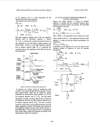
V. REDUCE THE OVERSHOOT WITH BODY BRAKE
International Rectifier Inc. has a trademark “body brake”
concept [3], which can significantly reduce the overshoot for
a step load from high current to low current. The concepj is
to turn off the synchronous FET as soon as the transient load
current starts from high to low. The equivalent diagram is
shown in Figure 7.
f-mw?%Bodydiodeo ~
synchrorous FET
Figure 7. The equivalent diagramwith body brake during the load transient
(current fmm high to low).
During the time period before inductor current goes to 101,
the voltage across the inductor is given as
di
L.-- -V,,,,, +V, (Body diode voltage drop)-(17)
dt
Since at low voltage application (e.g. Iv), the body diode
voltage drop is similar scale as output voltage, the inductor
current decreases almost as two times fast as the case
without body brake concept as shown in Figure 3 (a). As a
result, the voltage overshoot is greatly reduced. Replacing
the V,,,,,, with V,,,,,, cV, in equation (12) will give the
estimated overshoot with body brake concept as shown in
equation (1 8).
A VuVe”hmr
(R,.Al when Fc >Fzc
....... :I .......... :.......;........:_.......
i i j ii jijiiiiiii::::::::::::::::::;:::::::...........................
Figure 8. Operation waveform of the body brake concept implementation.
The implementation of body brake concept is simple. One
comparator is added to compare the output of voltage error
amplifier output and the body brake threshold, which is set
to be slightly lower than the minimum voltage of oscillator
ramp. During the load transient, when the load current
changes from high to low, the output voltage will start to
increase, the voltage feedback loop will respond and the
output of voltage compensator or error amplifier will start to
decrease rapidly. Once the output voltage of voltage
compensator is certain voltage lower than the minimum
voltage of PWM oscillator ramp, the comparator will disable
the synchronous FET driver and allow the output inductor
current flowing through the body diode of synchronous
FET. Assuming the body diode voltage drop is 0.7V, for the
case in.Section IV, 124 IOOuF ceramic capacitor, with body
brake concept, the overshoot when load current from IOOA
to OA will result in 30mV according to equation (IS), which
is about 40% improved comparing with 50mV result shown
in Table 3. The simulation verification is shown in Figure 9.
Loadcurrent
.....;........;........;........4........
::::::::::::::::I::::::::::::::::::::::::
.......................,......................_ L ........ _........_,.................
%re 1 SynchronousFE1driver
._ ~~ .,D. ........L ........C... .....,..................
. ......... .....,m
<m ........................................
n s
..,.........*.......I . ,
.’.
.,e (.?,I‘“. 3,s 11. 1 1 1
nnrln.,
Figure 9. Simulationresults for transient response with body brake forthe
case in Section IV.
VI. CASE OF MIXED OUTPUT CAPACITORS
If the output capacitors are more than one type, such as
combination of ceramic and OSCON capacitors, the analysis
is slightly difficult. One of possible solutions is to do a
simple simulation as shown in Figure IO.The set up for the
two current sources are defined in Figure 11. The voltage
shown in the output will give a good estimate of the voltage
overshoot during the transient.
Output voltage
Figure IO. Simple simulation schematic for transient load with mixed
output capacitors.
627
7. 2004 3.5rh Annual IEEE Power Elecrronics Specialists Conference Aachen, Germany, 2004
Output currentsource
(Load current )
lo1
lnp"tcurrentso102
(Inductor current)
wt=O At t l
At=Len*AlNarm
Figure II.Simulation setup for two currentsources.
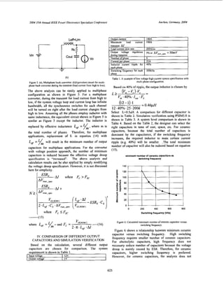
VU. EXPERIMENTAL VERIFICATION
International Rectifier introduced iPOWlR technology
which is a breakthrough in power density, efficiency and
simplicity for power conversion. The following experiment
shows a 4-phase application using IP2001 devices. The
'stem requirement is summarized in the following table.
........I..... .................................................................................................
imWtfhlemslEkkfMqriim
!
i...,........................
Figure 12. Internal Blockdiagram oflPZ00I.
Table 5. System specification
In reality, the ceramic capacitor is not ideal; the resistance
caused by layout is not negligible compare with the ESR of
ceramic. In addition, the previous analysis neglects the
output voltage ripple. In fact, the ripple ofthe output voltage
can contribute to the overall the voltage regulation
specification. More important, for multiphase application,
each channel has a phase delay referring to the other
channel. During the transient, it is impossible that all the
control switches will be turned off at same time. This delay
will cause more voltage droop or overshoot during the
transient. Therefore, the selected output ceramic capacitors
are more than the minimum capacitance. In this application,
the total capacitors are about 2000uF.
T s k m 1.00MSfs 33 Aces
r - 4
A:27.6mV
. . . .
. . .
. . . . . . . . . . . . . . .+ . . . . . . . . . . . . .
i . . . :. .
. .
: i : : :. .
i
. . . . . . I . . . . . .. . . .
. .
. . . . . . . . . . . . : . . T . . : . . . . . . . . . . .
. . .
. .
. . .
. ., , . ~: : i
M 5 0 . 0 ~ 1chl I I .35 9 Mar2002
10:04:56
Figure 13. Expenmental waveforms for output voltage ai 54A load current
transient.
VIII. CONCLUSION
The high-speed digital processor requires strict
requirement on the voltage regulator. In this paper, based on
a simplified circuit diagram, the relationship between
voltage overshoot, output inductor and output capacitors are
derived. Furthermore, an equation is derived to calculate the
minimum number of capacitors in order to meet the transient
specification. It shows that the minimum number of
capacitors is not only dependent on the ESR of capacitor,
but also the total capacitance. A comparison among
aluminum electrolytic, OSCON, polymer and ceramic
capacitors is given in details. Analysis along with
simulation verification is provided. This paper provides a
general guideline to choose the output capacitors based on
the system requirement.
ACKNOWLEDGMENT
The author would like to thank for the advise of professors
Keyue Smedley, Franco Maddaleno and the help of
colleagues Mark Yabut, Veng Tang, etc.
REFERENCES:
[I] Peng Xu; Jia Wei; Kaiwei Yao; Yu Meng; Lee, F.C.;
Investigation of candidate topologies for 12 V VRM Applied
Power Electronics Conference and Exposition. 2002. APEC
2002. Seventeenth Annual IEEE , Volume: 2 , 10-14 March
2002 Pa&): 686 -692 vol.
Pit-Leong Wong; Lee, F.C.; Peng Xu; Kaiwei Yao. Critical
inductance in voltage regulator modules; Applied Power
Electronics Conference and Exposition, 2002. APEC 2002.
Seventeenth Annual IEEE , Volume: 1 , 10-14 March 2002
Page($): 203 -209 v0l.l
[2]
131 1133086datasheet..
628