Download to read offline

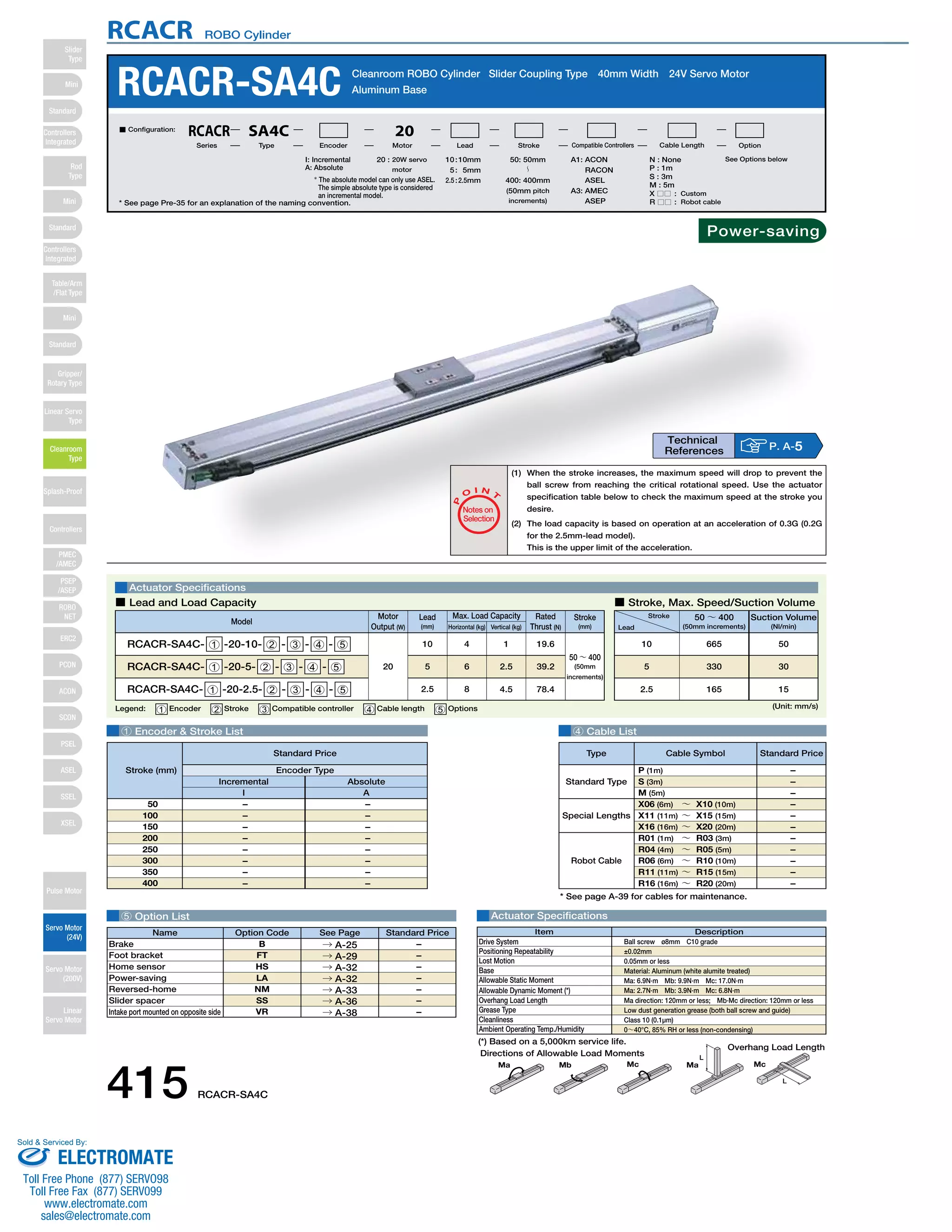
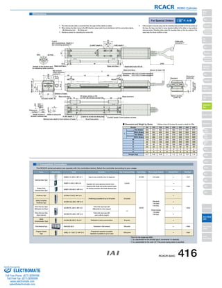

The document provides specifications for the RCACR-SA4C Cleanroom ROBO Cylinder Slider Coupling Type 40mm Width 24V Servo Motor, including its dimensions, weight, load capacity, speed, and compatible controllers. It lists options like brakes, foot brackets, and home sensors. Compatible controllers include the AMEC, ASEP, ACON and ASEL for applications like solenoid valves, positioning, pulse train input, and program control.