Kikusui Compact DC Power supply pwr01-denkei
•
0 likes•20 views

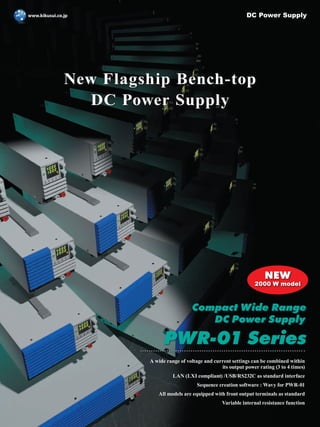
The PWR-01 is a series of high performance, multifunctional, compact, wide-range DC power supplies. It consists of 16 models in total with 4 maximum voltage outputs (L, ML, MH, and H) and 4 maximum power outputs (400 W, 800 W, 1200 W and 2000 W). The series is equipped with LAN (LXI), USB, and RS232C as standard interfaces that are essential for system integration. The PWR-01 also features front-facing output terminals, variable internal resistance, bleeder ON/OFF functions, CC/CV priority switching function, synchronized operation, various protections, and programmable internal memory. https://www.n-denkei.com/singapore/inquiry/

Recommended
More Related Content
What's hot
What's hot (20)
Similar to Kikusui Compact DC Power supply pwr01-denkei
Similar to Kikusui Compact DC Power supply pwr01-denkei (20)
More from NIHON DENKEI SINGAPORE
More from NIHON DENKEI SINGAPORE (20)
Recently uploaded
Recently uploaded (20)
Kikusui Compact DC Power supply pwr01-denkei
- 1. A wide range of voltage and current settings can be combined within its output power rating (3 to 4 times) LAN (LXI compliant) /USB/RS232C as standard interface Sequence creation software : Wavy for PWR-01 All models are equipped with front output terminals as standard Variable internal resistance function Compact Wide Range DC Power Supply PWR-01 Series DC Power Supply New Flagship Bench-top DC Power Supply 2000 W model NEW
- 2. 2 The PWR-01 is a series of high performance, multifunctional, compact, wide-range DC power supplies. It consists of 16 models in total with 4 maximum voltage outputs (L, ML, MH, and H) and 4 maximum power outputs (400 W, 800 W, 1200 W and 2000 W). The series is equipped with LAN (LXI), USB, and RS232C as standard interfaces that are essential for system integration. The PWR-01 also features front-facing output terminals, variable internal resistance, bleeder ON/OFF functions, CC/CV priority switching function, synchronized operation, various protections, and programmable internal memory. L, ML, MH, and H voltage types. Lineup of 16 models in total! ■Lineup The Bench-top Actual size New flagship bench-top DC power supply Type Model Voltage output Current output Power output L PWR401L 0 V to 40 V 0 A to 40 A 400 W PWR801L 0 A to 80 A 800 W PWR1201L 0 A to 120 A 1200 W PWR2001L 0 A to 200 A 2000 W Type Model Voltage output Current output Power output ML PWR401ML 0 V to 80 V 0 A to 20 A 400 W PWR801ML 0 A to 40 A 800 W PWR1201ML 0 A to 60 A 1200 W PWR2001ML 0 A to 100 A 2000 W Type Model Voltage output Current output Power output MH PWR401MH 0 V to 240 V 0 A to 5 A 400 W PWR801MH 0 A to 10 A 800 W PWR1201MH 0 A to 15 A 1200 W PWR2001MH 0 A to 25.0 A 2000 W Type Model Voltage output Current output Power output H PWR401H 0 V to 650 V 0 A to 1.85 A 400 W PWR801H 0 A to 3.70 A 800 W PWR1201H 0 A to 5.55 A 1200 W PWR2001H 0 A to 9.25 A 2000 W 40 V type 80 V type 240 V type 650 V type NEW NEW NEW
- 3. 3 PWR-01 Series Compact Wide Range DC Power Supply Universal Communication Interface Combined with Wide Range Output Coverage! Sequence Function Synchronized operation using trigger signals Communication Interface LAN (LXI compliant) /USB/RS232C as standard interface Front Output Terminals Equipped with front output terminal as standard *Up to 10 A Wide Range 3 to 4 times coverage ratio for voltage and current range Variable Internal Resistance Function Easy simulation of power supplies carrying internal resistance made possible Durable Performance Operating temperature guaranteed up to 50 ºC. at 50°C (122°F) capable of operating at full load continuously 50°C (122°F) Sequence Creation Software SD027-PWR-01 (Wavy for PWR-01) Convenient sequence generation for the PWR-01 Wavy Series For details, please refer to page 14 . *Storage temperature is -25 °C to +60 °C (-13 °F to 140 °F). 1200 W model 800 W model 400 W model 2000 W model NEW 2000 W model NEW
- 4. 4 Synchronized operation cable (LAN cable) Synchronized operation is even available in parallel operation May be combined with other models ● Output synchronization with same trigger ● Output synchronization using trigger IN/OUT 400 W 800 W×2 1200 W wait wait Trigger synchronization Trigger synchronization Trigger synchronization Trigger synchronization Trigger synchronization ■Sequence function The sequence function allows you to automatically execute programs that you have set in advance, one operation at a time. However, you cannot create sequences using only the panel. Sequence programs are created using commands from a PC. Once a sequence is executed via remote control, the program is saved onto the PWR-01's internal memory and then can be executed directly from the front panel without a PC. ■Safe and easy to use front-facing output terminals All models are equipped with front-facing output terminals (up to 10 A) optimized for bench-top use. Please connect to the output terminals with a safety plug. *This product's specifications were recorded using the back-side output terminals. Actual size ■Synchronized operation Synchronized operation allows for settings and sequence programs to be synchronized via trigger signals. Different PWR-01 models (e.g., 400 W model and 800 W model) can be easily mixed and matched with no difficulties. Synchronized operation is also possible in parallel operation. In order to successfully synchronize your power supplies, please configure various settings using remote control commands. After completing configuration, synchronized operation can be performed without a PC. ■Standard communication interface The series has been equipped with LAN (LXI), USB, and RS232C as standard interfaces, essential for system integration. When using RS232C, please order the D-sub 9P-RJ45 transformation cable (RD-8P/9P) option, sold seperately. The PWR-01 has also been equipped with J1/J2 connectors for analog control. Rear Panel : 400 W model TRG OUT J1 RS232C TRG IN USB LAN J2 ●Safety plugs (Options) TL41 (screw connection type) Red and black, one set each 1000 V/ CATǁ max 32 A TL42 (solder connection type) Red and black, one set each 1000 V/ CATǁ max 32 A Other PWR-01 series sequences can be restarted in synchronization with the PWR-01 series trigger output. Output changes can be synchronized with the same trigger signal. Sequence Function/Synchronized Operation Concept Map Actual size
- 5. 5 ■Series operation Up to two units can be connected in series (excluding the H type). The total combined output voltage of the two units is applied to the load. The voltage setting accuracy is the same as the accuracy of an individual unit. *You cannot perform master-slave configuration in series operation. ■Preset memory function The preset memory function of the PWR-01 allows you to save up to three combinations of each of the voltage, current, OVP, OCP and UVL values. The saved preset values can be recalled from the preset memory found on the front panel. ■CONFIG setting shortcut function You can register CONFIG setting parameters to the front panel's SC keys. You can perform tests efficiently by registering CONFIG parameters that you use frequently without consulting the CONFIG menu. Up to three parameters can be registered. ■Multi-channel (VMCB)* When multi-channel (VMCB) is used, one personal computer can be connected to multiple PWR-01 series machines (up to 31 units) to construct a virtual multi-channel power source system. This is effective for matching the control timing of multiple PWR-01 series units and for saving communication ports. ●Basic configuration with LAN interface and VMCB (example) ■Bleeder ON/OFF function The PWR-01's capacitor is connected to its output terminals, equipped with a bleeder circuit that discharges electricity when the OUTPUT is set to OFF. For example, when a battery is connected to the output terminal, or when the bleeder circuit is set to ON, the bleeder circuit will discharge electricity from the battery even when the OUTPUT is OFF. In cases like these, excessive electric discharge can be prevented by setting the bleeder circuit to OFF. This makes it possible to prevent current backflow from a battery without using a diode. Bleeder circuit Description Off *1 Bleeder circuit off Normal bleeder Bleeder circuit on Hyper bleeder *2 When a normal bleeder is used, falling time with no load can be shortened to approximately 70% and eliminate test cycle time. This is effective for situations in which one wants to operate ON/OFF with capacitive load as quickly as possible. *1. Even if the output terminals are open and the output is turned off or the voltage setting is at 0 V, up to several hundred millivolts of voltage may appear across the output terminals. *2. The fan speed is fixed to the maximum speed. ■Customizable startup when turning on output You can choose the priority operation mode (CC priority/CV priority) when the output is turned ON. This can prevent overshoot when turning on the output. ■Output ON/OFF delay function You can set the delay (DELAY TIME) from when the OUTPUT key is turned on or off to when the output actually turns on or off. This is useful for tests where precise timing/order of rise and drop voltage is essential according to the load characteristics. ■Soft start/stop function You can set the rise time and fall time of output current. This is useful when the load cannot follow the sudden rise or fall in the output current or when you want to avoid the overcurrent protection from being activated. ■Master-slave parallel operation One-control parallel operation is performed by designating one "master" device and connecting it to one or more of the same models being the "slave" devices. The entire system can then be controlled by operating the master machine. Output current can be greatly amplified (maximum output current: single rated output current x number of parallel units) with one-control parallel operation. The maximum number of parallel units including the master device is 3 units for the 400 W and 800 W models and 2 units for the 1200 W and 2000 W models. Differences in output voltage and output current between the master and slave devices are within approximately 5% of their respective rated output. ■Easy access with a built-in web server Use a browser from a PC, smartphone, or tablet to access the web server built into the PWR-01 series for convenient control and monitoring. Delay Delay On Off Off OUTPUT ON Output OUTPUT OFF Soft start time On Off Off OUTPUT ON Output OUTPUT OFF Soft stop time *virtual multi-channel bus (VMCB) Switching hub/ Broadband router Virtual group (Same domain number) Master ch 0 Slave ch 1 To LAN connector PWR-01 series To LAN connector Straight cable Slave ch 30 up to 31 units PC *Screen sample * Connecting with a smartphone, tablet, etc. requires a Wi-Fi environment (wireless LAN router etc.).
- 6. 6 J2 connector pin arrangement ■External analog control function The PWR-01 series is equipped with external voltage/resistance control, which is necessary for external analog control and monitoring applications for power supply testing. The input external signal and the output status signal can be accessed through the J1/J2 connectors on the rear panel. When using the J1/J2, please purchase the J1/J2 connector plug kit (OP01-PWR-01) option, sold separately. ●Controlling the output voltage & output current. ▼Control using an external voltage. It is possible to control the output voltage/output current of the PWR-01 series by using an external voltage. ▼Control using an external resistance. It is possible to control the output voltage/output current of the PWR-01 series by using an external variable resistor. ▼Turning output on and off using an external contact. It is possible to turn the output ON/OFF of the PWR-01 series by using an external contact. ▼Output shutdown control using an external contact. It is possible to turn the output OFF of the PWR-01 series by using an external contact. ▼Clearing alarms using an external contact. It is possible to clear the alarm of the PWR-01 series by using an external contact. ▼Monitoring operation modes. External monitoring of the output voltage and output current. Pin No. Signal name Description J1-1 VPGM Terminal used to control the output voltage with an external voltage or external resistance. 0 V to 5 V; 0 % to 100 % of the rated output voltage (CF12: LO). 0 V to 10 V; 0 % to 100 % of the rated output voltage (CF12: HI). J1-2 VMON Output voltage monitor. 0 % to 100 % of the rated output voltage is gener- ated as a voltage between 0 V and 5 V (CF13: LO) or a voltage between 0 V and 10 V (CF13: HI). J1-3 REF OUT Reference voltage for external resistance control. 5.25 V (CF12: LO) / 10.5 V (CF12: HI), maximum output current: 2.5 mA. J1-4 PRL ON On when parallel operation is in use and when output is on (output through an open-collector photo-coupler) J1-5 A GND External signal common for pins 1 to 3, 6 to 9, 11, 12, 14, 16, and 20. When remote sensing is not used, this is at the same electric potential as the negative output terminal. When remote sensing is used, this is at the same electric potential as the negative electrode (-S) of sensing input. J1-6 ALM CLEAR Alarm clear terminal. Alarms are cleared when a low level signal(0 V to 0.5 V) is received or shorted. J1-7 I SUM Current output terminal for parallel operation. J1-8 PRL OUT Positive output terminal for parallel operation. J1-9 PRL COMP IN Correction signal input terminal for parallel operation. J1-10 A GND External signal common for pins 1 to 3, 6 to 9, 11, 12, 14, 16, and 20. When remote sensing is not used, this is at the same electric potential as the negative output terminal. When remote sensing is used, this is at the same electric potential as the negative electrode (-S) of sensing input. J1-11 IPGM Terminal used to control the output current with an external voltage or external resistance. 0 V to 5 V; 0 % to 100 % of the rated output current (CF12: LO). 0 V to 10 V; 0 % to 100 % of the rated output current (CF12: HI). J1-12 IMON Output current monitor. 0 % to 100 % of the rated output current is generated as a voltage between 0 V and 5 V (CF13: LO) or a voltage between 0 V and 10 V (CF13: HI). J1-13 PRL COM Common for pin 4. J1-14 PRL ALM On when a protection function is activated during parallel operation or when an output shutdown signal is being received. J1-15 A GND External signal common for pins 1 to 3, 6 to 9, 11, 12, 14, 16, and 20. When remote sensing is not used, this is at the same electric potential as the negative output terminal. When remote sensing is used, this is at the same electric potential as the negative electrode (-S) of sensing input. J1-16 SHUT DOWN Output shutdown control terminal. The output is turned off when set to LOW (0 V to 0.5 V) or shorted. J1-17 OUTPUT CONT Output on/off terminal. On when set to LOW(0 V to 0.5 V) or shorted; off when set to HIGH(4.5 V or 5 V) or open (CF15: LO) On when set to HIGH(4.5 V to 5 V) or open; off when set to LOW(0 V or 0.5 V) or shorted (CF15: HI) J1-18 PRL COMP OUT Correction signal output terminal for parallel operation. J1-19 PRL IN- Negative input terminal for parallel operation. J1-20 PRL IN+ Positive input terminal for parallel operation. J1 connector pin arrangement Pin No. Signal name Description J2-1 STATUS COM Common for pins 2 to 6. *1 J2-2 OUT ON STATUS Outputs a signal when output is on (output through an open-collector photocoupler). *2 J2-3 PWR ON STATUS Outputs a low level signal when the power is on (output through an open-collector photocoupler). *2 J2-4 ALM STATUS Outputs a signal when a protection function (OVP, OCP, FOCP, OHP, SENSE, AC-FAIL) is activated or when an output shutdown signal is being received (output through an open-collector photocoupler). *2 J2-5 CV STATUS Outputs a signal during CV mode (output through an open-collector photocoupler) *2 J2-6 CC STATUS Outputs a signal during CC mode (output through an open-collector photocoupler). *2 *1. The status common is floating (isolation voltage of 800 V or less). It is isolated from the control circuit. *2. Open collector output:Maximum voltage: 30 V. Maximum current: 8 mA. 2-core shielded wire or twisted pair wires Vext + – Output terminal J1 PWR-01 2-core shielded wire or twisted pair wires Rext Output termina J1 PWR-01 Vext Wiper 2-core shielded wire or twisted pair wires S Output termina J1 PWR-01 2-core shielded wire or twisted pair wires S Output termina J1 PWR-01 2-core shielded wire or twisted pair wires S Output termina J1 PWR-01 J1 and J2 connectors J1 connector J2 connector Connector type WF2549-2WR10S3T01 (WCON) WF2549-2WR03S3T01(WCON) Housing type WF2549-2H10W01 (WCON) WF2549-2H03W01 (WCON) Terminal (pin) WF2549-TPS302 (WCON) WF2549-TPS302 (WCON) Wire diameter (core wire) AWG22 or AWG24 AWG22 or AWG24 Manual pressure welding tool SN-28B (IWISS) or an equivalent product SN-28B (IWISS) or an equivalent product CONFIG setting is easy for ON/OFF settings with external contact points that can be easily accessed from the front panel.
- 7. 7 ■Variable internal resistance function The variable internal resistance function enables you to easily simulate the internal resistance of rechargeable batteries, solar batteries, fuel cells, and the like. By setting the internal resistance value in constant voltage (CV) mode, you can decrease the output voltage according to the output current. You can use a CONFIG setting to set the internal resistance. v 0 I Variable internal resistance function of power Solar batteries Rechargeable batteries Fuel cells Power conditioner Power tools PWR-01 series Variable internal resistance function Fuel cell vehicle ■3 to 4 times ratio power operation 3 to 4 times ratio power operating range covers a wide variety of voltage and current setting combinations. For example, the 1200 W rated power output PWR1201ML is capable of seamless operation from 80 V/15 A to 20 V/60 A. ●Setting range Vrtg rated output voltage Irtg rated output current Rint internal resistance 0 <Rint (min) ≤Rint (max) L type, ML type: Rint (max)= Vrtg/ Irtg MH type, H type: Rint (max)= Vrtg/ Irtg x 3/4 PWR401L PWR401ML PWR401MH PWR401H Vrtg [V] 40 80 240 650 Irtg [A] 40 20 5 1.85 Rint [Ω] 0.001 to 1.000 0.001 to 4.000 0.01 to 36.00 0.1 to 263.5 Resolution *1 0.001 0.001 0.01 0.1 PWR801L PWR801ML PWR801MH PWR801H Vrtg [V] 40 80 240 650 Irtg [A] 80 40 10 3.7 Rint [Ω] 0.001 to 0.500 0.001 to 2.000 0.01 to 18.00 0.1 to 131.8 Resolution*1 0.001 0.001 0.01 0.1 PWR1201L PWR1201ML PWR1201MH PWR1201H Vrtg [V] 40 80 240 650 Irtg [A] 120 60 15 5.55 Rint [Ω] 0.001 to 0.333 0.001 to 1.333 0.01 to 12.00 0.1 to 87.84 Resolution*1 0.001 0.001 0.01 0.01 PWR2001L PWR2001ML PWR2001MH PWR2001H Vrtg [V] 40 80 240 650 Irtg [A] 200 100 25 9.25 Rint [Ω] 0.001 to 0.200 0.001 to 0.800 0.01 to 7.20 0.01 to 52.70 Resolution*1 0.001 0.001 0.01 0.01 *1. Resolution when FINE is in use The maximum internal resistance that can be set during parallel operation is the value obtained by dividing Rint (max) during standalone operation by the number of units in parallel operation. The resolution is the value obtained by dividing the resolution during standalone operation by the number of units in parallel operation. The variable internal resistance function can be configured only in constant voltage(CV) mode. Output current (A) Output voltage (V) 35 30 45 40 25 20 15 10 5 0 0 5 10 15 20 25 30 45 0 10 20 30 40 50 60 35 70 40 80 90 0 15 30 45 60 75 90 105 120 135 0 25 50 75 100 125 150 175 200 225 Rated output current Rated output power [L type] Operating range Rated output voltage: 40 V PWR401L PWR801L PWR1201L PWR2001L Rated output power PWR401L: 400 W PWR801L: 800 W PWR1201L: 1200 W PWR2001L: 2000 W Output voltage (V) 60 30 90 40 80 70 20 50 10 0 0 2.5 5 7.5 10 12.5 15 22.5 0 5 10 15 20 25 30 17.5 35 20 40 45 0 7.5 15 22.5 30 37.5 45 52.5 60 67.5 Output current (A) 0 12.5 25 37.5 50 62.5 75 87.5 100 112.5 Rated output current Rated output power [ML type] Operating range Rated output voltage: 80 V PWR401ML PWR801ML PWR1201ML Rated output power PWR401ML: 400 W PWR801ML: 800 W PWR1201ML: 1200 W PWR2001ML: 2000 W PWR2001ML Output voltage (V) 300 250 200 50 150 100 0 0 0.5 1 2.5 3 4 0 1 2 1.5 3 5 2 4 6 3.5 7 8 4.5 9 5 10 5.5 11 6 5 . 7 5 . 4 3 5 . 1 0 9 10.5 12 13.5 15 16.5 Rated output current Rated output power Rated output power Rated output voltage: 240 V PWR401MH PWR801MH PWR1201MH [MH type] Operating range PWR401MH: 400 W PWR801MH: 800 W PWR1201MH: 1200 W PWR2001MH: 2000 W Output current (A) 5 . 7 2 5 2 5 . 2 2 0 2 5 . 7 1 5 1 0 1 5 . 2 1 5 . 7 5 5 . 2 0 PWR2001MH Output voltage (V) 700 600 500 100 200 400 300 0 0 0.2 0.4 1 1.2 1.6 0 0.4 0.8 0.6 1.2 2 0.8 1.6 2.4 1.4 2.8 3.2 1.8 3.6 2 4 0 0.6 1.2 1.8 6 4 . 5 8 . 4 2 . 4 6 . 3 4 . 2 3 Rated output current Rated output power Rated output power Rated output voltage: 650 V PWR401H PWR801H PWR1201H [H type] Operation range PWR401H: 400 W PWR801H: 800 W PWR1201H: 1200 W PWR2001H: 2000 W Output current (A) 0 1 2 3 5 4 6 7 8 9 10 PWR2001H (4x ratio) (3x ratio) (4x ratio) (3x ratio)
- 8. 8 ■ Specifications Item/Model PWR401L PWR401ML PWR401MH PWR401H AC input Nominal input rating 100 Vac to 240 Vac, 50 Hz to 60 Hz, single phase Input voltage range 85 Vac to 265 Vac Input frequency range 47 Hz to 63 Hz Current (TYP) *1 100 Vac 5.6 A 200 Vac 2.8 A Inrush current (MAX) *2 25 Apeak or less Power (MAX) *3 560 VA Power factor (TYP) *1 0.99 (input voltage: 100 V), 0.97 (input voltage: 200 V) Efficiency (MIN) *1 75 % (TYP) Hold-up time for power interruption (MIN) *3 20 ms or more ● 400 W model *1. At the rated output power for the rated output current. *2. Excludes the charge current component that flows through the capacitor of the internal EMC filter circuit immediately after the POWER switch is turned on (for approximately 1 ms). *3. 100 Vac, at the rated output power. *1. The maximum output voltage and maximum output current are limited by the maximum output power. *2. Can be limited to approximately 95 % of the OVP trip point or OCP trip point. *3. 85 Vac to 135 Vac or 170 Vac to 265 Vac, fixed load *4. The amount of change that occurs when the load is changed from no load to full load (rated output power/rated output voltage) with rated output voltage. The value is measured at the sensing point. *5. The amount of time required for the output voltage to return to a value within "rated output voltage ± (0.1 % +10 mV)." The load current fluctuation is 50 % to 100 % of the maximum current with the set output voltage. *6. Measured using an RC-9131C probe that conforms to the JEITA specifications. At the rated output current. *7. When the measurement frequency bandwidth is 10 Hz to 20 MHz. *8. When the measurement frequency bandwidth is 10 Hz to 1 MHz. *9. When the bleeder circuit is set to bleeder normal. *10. When the ambient temperature is within 0°C and 50 °C *11. Applies to the range of 1 % to 100 % of the rated current. TYP (0.1 % of rating) for 0 % to 1 %. *12. When the output voltage is 10 % to 100 % of the rating. At the rated output current. Item/Model PWR401L PWR401ML PWR401MH PWR401H Output Rating Output voltage *1 40 V 80 V 240 V 650 V Output current *1 40 A 20 A 5 A 1.85 A Output power 400 W Voltage Maximum settable voltage *2 42 V 84 V 252 V 682.5 V Setting accuracy ± (0.05 % of set +0.05 % of rating) Resolution 200 mV 400 mV 1000 mV 2500 mV Using FINE, OUT OFF 10 mV 10 mV 100 mV 100 mV Using FINE, OUT ON 1 mV 1 mV 10 mV 10 mV When using a communication interface 0.1 mV 0.1 mV 0.1 mV 0.1 mV Line regulation *3 ±6 mV ±10 mV ±26 mV ±67 mV Load regulation *4 ±6 mV ±10 mV ±26 mV ±67 mV Transient response *5 1 ms or less 2 ms or less 2 ms or less 3 ms or less Ripple noise *6 p-p *7 50 mV 50 mV 100 mV 300 mV rms *8 5 mV 5 mV 20 mV 50 mV Rise time At full load 50 ms or less 100 ms or less No load 50 ms or less 100 ms or less Fall time *9 At full load 50 ms or less 150 ms 250 ms No load 500 ms or less 1200 ms 2000 ms Maximum remote sensing compen- sation voltage (single line) 1.5 V 4 V 5 V 5 V Temperature coefficient *10 100 ppm/°C Current Maximum settable current *2 42 A 21 A 5.25 A 1.9425 A Setting accuracy *11 ± (0.5 % of set +0.1 % of rating) Resolution 200 mA 100 mA 20 mA 10 mA Using FINE, OUT OFF 10 mA 10 mA 1 mA 1 mA Using FINE, OUT ON 1 mA 1 mA 0.1 mA 0.1 mA When using a communication interface 0.1 mA 0.1 mA 0.1 mA 0.1 mA Line regulation ±6 mA ±4 mA ±2.5 mA ±2.2 mA Load regulation ±13 mA ±9 mA ±6.0 mA ±5.4 mA Ripple noise *12 rms *8 80 mA 40 mA 12 mA 6 mA Rise time (TYP) At full load 50 ms 100 ms Fall time (TYP) At full load 50 ms 100 ms Temperature coefficient *10 100 ppm/°C Maximum internal resistance that can be set 1.000 Ω 4.000 Ω 36.00 Ω 263.5 Ω Item/Model PWR401L PWR401ML PWR401MH PWR401H Display function Voltage display Maximum display 99.99 999.9 Display accuracy ± (0.2 % of reading + 5 digit) Current display Maximum display 99.99 9.999 Display accuracy ± (0.5 % of reading + 8 digit) Power display The PWR DSPL LED lights in red. Maximum display 9999 Display accuracy Displays the result of multiplying the current and voltage. The display is toggled with the voltage or current display. Unless specified otherwise, the specifications are for the following settings and conditions. ●Loads are pure resistive loads. ●The product is warmed up for at least 30 minutes (with current flowing). ●After warm-up, the product must be calibrated correctly in a 23 °C ± 5 °C environment according to the appropriate calibration procedure. ●Values indicated by “TYP” are typical values. They are not guaranteed performance values. ●Values indicated by “rating” are ratings. ●Values indicated by “reading” are readings. ●Values indicated by "f.s." are full scale values. ●The PWR-01 operates over a wide range of output voltage and output current within rated output power. However, the current that can be output with rated output voltage and the voltage that can be output with rated output current are limited by the rated output power. ●The current that can be output with rated output voltage and the voltage that can be output with rated output current are as follows. Maximum output current with rated output voltage = Rated output power/ rated output voltage. Maximum output voltage with rated output current = Rated output power/ rated output current. ●Rated load and no load are defined as follows:In constant-voltage mode (when the output current is set to a value greater than or equal to the maximum output current with rated output voltage) Rated load: Refers to a resistive load that, when the rated output voltage is applied,makes the flowing current 95 % to 100 % of the maximum output current with rated output voltage.No load:Refers to a load through which no output current flows. In other words,refers to an open load (no load being connected). In constant-current mode (when the output voltage is set to a value greater than or equal to the maximum output voltage with rated output current) Rated load:Refers to a resistive load that, when the rated output current flows, makes the voltage drop to 95 % to 100 % of the maximum output voltage with rated output current. Including the voltage drop in the load cables, the PWR-01 output voltage must not exceed the maximum output voltage with rated output current. No load:Refers to a resistive load that, when the rated output current flows, makes the voltage drop to 10 % of the maximum output voltage with rated output current or 1 V whichever is higher. ●The specifications of the PWR-01 apply to the rear-panel output terminals.
- 9. 9 *1. At the rated output power for the rated output current. *2. Excludes the charge current component that flows through the capacitor of the internal EMC filter circuit immediately after the POWER switch is turned on (for approximately 1 ms). *3. 100 Vac, at the rated output power. *1. The maximum output voltage and maximum output current are limited by the maximum output power. *2. Can be limited to approximately 95 % of the OVP trip point or OCP trip point. *3. 85 Vac to 135 Vac or 170 Vac to 265 Vac, fixed load *4. The amount of change that occurs when the load is changed from no load to full load (rated output power/rated output voltage) with rated output voltage. The value is measured at the sensing point. *5. The amount of time required for the output voltage to return to a value within "rated output voltage ± (0.1 % +10 mV)." The load current fluctuation is 50 % to 100 % of the maximum current with the set output voltage. *6. Measured using an RC-9131C probe that conforms to the JEITA specifications. At the rated output current. *7. When the measurement frequency bandwidth is 10 Hz to 20 MHz. *8. When the measurement frequency bandwidth is 10 Hz to 1 MHz. *9. When the bleeder circuit is set to bleeder normal. *10. When the ambient temperature is within 0°C and 50 °C *11. Applies to the range of 1 % to 100 % of the rated current. TYP (0.1 % of rating) for 0 % to 1 %. *12. When the output voltage is 10 % to 100 % of the rating. At the rated output current. Item/Model PWR801L PWR801ML PWR801MH PWR801H AC input Nominal input rating 100 Vac to 240 Vac, 50 Hz to 60 Hz, single phase Input voltage range 85 Vac to 265 Vac Input frequency range 47 Hz to 63 Hz Current (TYP) *1 100 Vac 11.2 A 200 Vac 5.6 A Inrush current (MAX) *2 50 Apeak or less Power (MAX) *3 1120 VA Power factor (TYP) *1 0.99 (input voltage: 100 V), 0.97 (input voltage: 200 V) Efficiency (MIN) *1 75 % (TYP) Hold-up time for power interruption (MIN) *3 20 ms or more ● 800 W model Item/Model PWR801L PWR801ML PWR801MH PWR801H Output Rating Output voltage *1 40 V 80 V 240 V 650 V Output current *1 80 A 40 A 10 A 3.70 A Output power 800 W Voltage Maximum settable voltage *2 42 V 84 V 252 V 682.5 V Setting accuracy ± (0.05 % of set +0.05 % of rating) Resolution 200 mV 400 mV 1000 mV 2500 mV Using FINE, OUT OFF 10 mV 10 mV 100 mV 100 mV Using FINE, OUT ON 1 mV 1 mV 10 mV 10 mV When using a communication interface 0.1 mV 0.1 mV 0.1 mV 0.1 mV Line regulation *3 ±6 mV ±10 mV ±26 mV ±67 mV Load regulation *4 ±6 mV ±10 mV ±26 mV ±67 mV Transient response *5 1 ms or less 2 ms or less 2 ms or less 3 ms or less Ripple noise *6 p-p *7 50 mV 50 mV 100 mV 300 mV rms *8 5 mV 5 mV 20 mV 50 mV Rise time At full load 50 ms or less 100 ms or less No load 50 ms or less 100 ms or less Fall time *9 At full load 50 ms or less 150 ms 250 ms No load 500 ms or less 1200 ms 2000 ms Maximum remote sensing compen- sation voltage (single line) 1.5 V 4 V 5 V 5 V Temperature coefficient *10 100 ppm/°C Current Maximum settable current *2 84 A 42 A 10.5 A 3.885 A Setting accuracy *11 ± (0.5 % of set +0.1 % of rating) Resolution 400 mA 200 mA 40 mA 20 mA Using FINE, OUT OFF 10 mA 10 mA 10mA 1 mA Using FINE, OUT ON 1 mA 1 mA 1 mA 0.1 mA When using a communication interface 0.1 mA 0.1 mA 0.1 mA 0.1 mA Line regulation ±10 mA ±6 mA ±3 mA ±2.4 mA Load regulation ±21 mA ±13 mA ±7 mA ±5.7 mA Ripple noise *12 rms *8 160 mA 80 mA 24 mA 12 mA Rise time (TYP) At full load 50 ms 100 ms Fall time (TYP) At full load 50 ms 100 ms Temperature coefficient *10 100 ppm/°C Maximum internal resistance that can be set 0.500 Ω 2.000 Ω 18.00 Ω 131.8 Ω Item/Model PWR801L PWR801ML PWR801MH PWR801H Display function Voltage display Maximum display 99.99 999.9 Display accuracy ± (0.2 % of reading + 5 digit) Current display Maximum display 99.99 9.999 Display accuracy ± (0.5 % of reading + 8 digit) Power display The PWR DSPL LED lights in red. Maximum display 9999 Display accuracy Displays the result of multiplying the current and voltage. The display is toggled with the voltage or current display.
- 10. 10 Item/Model PWR1201L PWR1201ML PWR1201MH PWR1201H AC input Nominal input rating 100 Vac to 240 Vac, 50 Hz to 60 Hz, single phase Input voltage range 85 Vac to 265 Vac Input frequency range 47 Hz to 63 Hz Current (TYP) *1 100 Vac 16.8 A 200 Vac 8.4 A Inrush current (MAX) *2 75 Apeak or less Power (MAX) *3 1680 VA Power factor (TYP) *1 0.99 (input voltage: 100 V), 0.97 (input voltage: 200 V) Efficiency (MIN) *1 75 % (TYP) Hold-up time for power interruption (MIN) *3 20 ms or more Item/Model PWR1201L PWR1201ML PWR1201MH PWR1201H Output Rating Output voltage *1 40 V 80 V 240 V 650 V Output current *1 120 A 60 A 15.0 A 5.55 A Output power 1200 W Voltage Maximum settable voltage *2 42 V 84 V 252 V 682.5 V Setting accuracy ± (0.05 % of set +0.05 % of rating) Resolution 200 mV 400 mV 1000 mV 2500 mV Using FINE, OUT OFF 10 mV 10 mV 100 mV 100 mV Using FINE, OUT ON 1 mV 1 mV 10 mV 10 mV When using a communication interface 0.1 mV 0.1 mV 0.1 mV 0.1 mV Line regulation *3 ±6 mV ±10 mV ±26 mV ±67 mV Load regulation *4 ±6 mV ±10 mV ±26 mV ±67 mV Transient response *5 1 ms or less 2 ms or less 2 ms or less 3 ms or less Ripple noise *6 p-p *7 50 mV 50 mV 100 mV 300 mV rms *8 5 mV 5 mV 20 mV 50 mV Rise time At full load 50 ms or less 100 ms or less No load 50 ms or less 100 ms or less Fall time *9 At full load 50 ms or less 150 ms 250 ms No load 500 ms or less 1200 ms 2000 ms Maximum remote sensing compen- sation voltage (single line) 1.5 V 4 V 5 V 5 V Temperature coefficient *10 100 ppm/°C Current Maximum settable current *2 126 A 63 A 15.75 A 5.8275 A Setting accuracy *11 ± (0.5 % of set +0.1 % of rating) Resolution 600 mA 300 mA 60 mA 30 mA Using FINE, OUT OFF 100 mA 10 mA 10 mA 1 mA Using FINE, OUT ON 10 mA 1 mA 1 mA 0.1 mA When using a communication interface 0.1 mA 0.1 mA 0.1 mA 0.1 mA Line regulation ±14 mA ±8 mA ±3.5 mA ±2.6 mA Load regulation ±29 mA ±17 mA ±8.0 mA ±6.1 mA Ripple noise *12 rms *8 240 mA 120 mA 36 mA 18 mA Rise time (TYP) At full load 50 ms 100 ms Fall time (TYP) At full load 50 ms 100 ms Temperature coefficient *10 100 ppm/°C Maximum internal resistance that can be set 0.333 Ω 1.333 Ω 12.00 Ω 87.84 Ω Item/Model PWR1201L PWR1201ML PWR1201MH PWR1201H Display function Voltage display Maximum display 99.99 999.9 Display accuracy ± (0.2 % of reading + 5 digit) Current display Maximum display 999.9 99.99 9.999 Display accuracy ± (0.5 % of reading + 8 digit) Power display The PWR DSPL LED lights in red. Maximum display 9999 Display accuracy Displays the result of multiplying the current and voltage. The display is toggled with the voltage or current display. ■ Specifications ● 1200 W model *1. At the rated output power for the rated output current. *2. Excludes the charge current component that flows through the capacitor of the internal EMC filter circuit immediately after the POWER switch is turned on (for approximately 1 ms). *3. 100 Vac, at the rated output power. *1. The maximum output voltage and maximum output current are limited by the maximum output power. *2. Can be limited to approximately 95 % of the OVP trip point or OCP trip point. *3. 85 Vac to 135 Vac or 170 Vac to 265 Vac, fixed load *4. The amount of change that occurs when the load is changed from no load to full load (rated output power/rated output voltage) with rated output voltage. The value is measured at the sensing point. *5. The amount of time required for the output voltage to return to a value within "rated output voltage ± (0.1 % +10 mV)." The load current fluctuation is 50 % to 100 % of the maximum current with the set output voltage. *6. Measured using an RC-9131C probe that conforms to the JEITA specifications. At the rated output current. *7. When the measurement frequency bandwidth is 10 Hz to 20 MHz. *8. When the measurement frequency bandwidth is 10 Hz to 1 MHz. *9. When the bleeder circuit is set to bleeder normal. *10. When the ambient temperature is within 0°C and 50 °C *11. Applies to the range of 1 % to 100 % of the rated current. TYP (0.1 % of rating) for 0 % to 1 %. *12. When the output voltage is 10 % to 100 % of the rating. At the rated output current.
- 11. 11 Item/Model PWR2001L PWR2001ML PWR2001MH PWR2001H AC input Nominal input rating 100 Vac to 240 Vac, 50 Hz to 60 Hz, single phase Input voltage range 85 Vac to 265 Vac Input frequency range 47 Hz to 63 Hz Current (TYP) *1 100 Vac 28.0 A 200 Vac 14.0 A Inrush current (MAX) 125 Apeak or less Power (MAX) *2 2800 VA Power factor (TYP) *1 0.99 (input voltage: 100 V), 0.97 (input voltage: 200 V) Efficiency (MIN) *1 75 % (TYP) Hold-up time for power interruption (MIN) *2 20 ms or more Item/Model PWR2001L PWR2001ML PWR2001MH PWR2001H Output Rating Output voltage *1 40 V 80 V 240 V 650 V Output current *1 200 A 100 A 25.0 A 9.25 A Output power 2000 W Voltage Maximum settable voltage *2 42 V 84 V 252 V 682.5 V Setting accuracy ± (0.05 % of set +0.05 % of rating) Resolution 200 mV 400 mV 1000 mV 2500 mV Using FINE, OUT OFF 10 mV 10 mV 100 mV 100 mV Using FINE, OUT ON 1 mV 1 mV 10 mV 10 mV When using a communication interface 0.1 mV 0.1 mV 0.1 mV 0.1 mV Line regulation *3 ±6 mV ±10 mV ±26 mV ±67 mV Load regulation *4 ±6 mV ±10 mV ±26 mV ±67 mV Transient response *5 1 ms or less 2 ms or less 2 ms or less 3 ms or less Ripple noise *6 p-p *7 50 mV 70 mV 120 mV 350 mV rms *8 5 mV 5 mV 20 mV 50 mV Rise time At full load 50 ms or less 100 ms or less No load 50 ms or less 100 ms or less Fall time *9 At full load 50 ms or less 150 ms or less 250 ms or less No load 500 ms or less 1200 ms or less 2000 ms or less Maximum remote sensing compen- sation voltage (single line) 1.5 V 4 V 5 V 5 V Temperature coefficient *10 100 ppm/°C Current Maximum settable current *2 210 A 105 A 26.25 A 9.7125 A Setting accuracy *11 ± (0.5 % of set +0.1 % of rating) Resolution 1000 mA 500 mA 100 mA 50 mA Using FINE, OUT OFF 100 mA 100 mA 10 mA 10 mA Using FINE, OUT ON 10 mA 10 mA 1 mA 1 mA When using a communication interface 0.1 mA 0.1 mA 0.1 mA 0.1 mA Line regulation ±22 mA ±12 mA ±4.5 mA ±2.9 mA Load regulation ±45 mA ±25 mA ±10.0 mA ±6.9 mA Ripple noise *12 rms *8 400 mA 200 mA 60 mA 30 mA Rise time (TYP) At full load 50 ms 100 ms Fall time (TYP) At full load 50 ms 100 ms Temperature coefficient *10 100 ppm/°C Maximum internal resistance that can be set 0.200 Ω 0.800 Ω 7.200 Ω 52.70 Ω Item/Model PWR2001L PWR2001ML PWR2001MH PWR2001H Display function Voltage display Maximum display 99.99 999.9 Display accuracy ± (0.2 % of reading + 5 digit) Current display Maximum display 999.9 99.99 Display accuracy ± (0.5 % of reading + 8 digit) Power display The PWR DSPL LED lights in red. Maximum display 9999 Display accuracy Displays the result of multiplying the current and voltage. The display is toggled with the voltage or current display. ● 2000 W model NEW *1. At the rated output power for the rated output current. *2. 100 Vac, at the rated output power. *1. The maximum output voltage and maximum output current are limited by the maximum output power. *2. Can be limited to approximately 95 % of the OVP trip point or OCP trip point. *3. 85 Vac to 135 Vac or 170 Vac to 265 Vac, fixed load *4. The amount of change that occurs when the load is changed from no load to full load (rated output power/rated output voltage) with rated output voltage. The value is measured at the sensing point. *5. The amount of time required for the output voltage to return to a value within "rated output voltage ± (0.1 % +10 mV)." The load current fluctuation is 50 % to 100 % of the maximum current with the set output voltage. *6. Measured using an RC-9131C probe that conforms to the JEITA specifications. At the rated output current. *7. When the measurement frequency bandwidth is 10 Hz to 20 MHz. *8. When the measurement frequency bandwidth is 10 Hz to 1 MHz. *9. When the bleeder circuit is set to bleeder normal. *10. When the ambient temperature is within 0°C and 50 °C *11. Applies to the range of 1 % to 100 % of the rated current. TYP (0.1 % of rating) for 0 % to 1 %. *12. When the output voltage is 10 % to 100 % of the rating. At the rated output current.
- 12. 12 Item/Model 400 W 800 W 1200 W 2000 W Protection functions Overvoltage protection (OVP) Turns the output off *1, displays OVP, and lights ALM Setting range 10 % to 112 % of the rated output voltage Setting accuracy ± (1.5 % of rating) Overcurrent protection (OCP) *2 Turns the output off *1, displays OCP, and lights ALM Setting range 10 % to 112 % of the rated output current Setting accuracy ± (3 % of rating) Front-panel output terminal overcurrent Turns the output off *1, displays FOCP, and lights ALM protection (FOCP)*3 Value (fixed) 11 A (TYP) Undervoltage limit (UVL) Cannot be set to a value less than or equal to the set voltage Setting range 0 % to 105 % of the rated output voltage Overheat protection (OHP) Turns the output off, displays OHP, and lights ALM Incorrect sensing connection protection (SENSE) Turns the output off, displays SENS, and lights ALM Low AC input protection (AC-FAIL) Turns the output off *4, displays AC, and lights ALM Shutdown (SD) Turns the output off *1, displays SD, and lights ALM Power limit (POWER LIMIT) ALM blinking Value (fixed) Approx. 105% of the rated output power Communication monitoring (watchdog) Turns the output off, displays WDOG, and lights ALM Master-slave parallel operation protection (PRL ALM) Turns the output off *1, displays PRL, and lights ALM *1. Output off or breaker trip on the 2000 W model. *2. This does not protect against the discharge current peak that is generated from the capacitors inside the PWR-01 output section when the load is changed suddenly. *3. Available on models with a maximum settable current of 11 A or more. If the OCP value is less than the FOCP value, the OCP value takes precedence. *4. Auto recovery after eliminating the cause of the alarm is selectable. Item/Model 400 W 800 W 1200 W 2000 W Signal output and input Monitor signal output Voltage monitor (VMON) Selectable monitor voltage range: 0 V to 5 V or 0 V to 10 V Setting accuracy 2.5 % of f.s. *1 Current monitor (IMON) Selectable monitor voltage range: 0 V to 5 V or 0 V to 10 V Setting accuracy 2.5 % of f.s. *1 Status signal output *2 OUTON STATUS On when output is on. CV STATUS Turns on during CV operation CC STATUS Turns on during CC operation ALARM STATUS Turns on when an alarm has been activated POWER ON STATUS Turns on when the power is turned on Trigger signal Input (TRG IN) Logic selectable: LOW (0 V to 1.5 V), HIGH (3.5 V to 5 V) Input impedance: 10 kΩ (TYP) Output (TRG OUT) Logic selectable: LOW (0 V to 0.6 V), HIGH (4.2 V to 5 V) Pulse width: 100 μs (TYP) *1. f.s. is the full scale at the selected range. It is 10 V for the 10 V range and 5 V for the 5 V range. *2. Photocoupler open collector output; maximum voltage 30 V, maximum current (sink) 8 mA; isolated from the output and control circuits; status commons are floating (withstand voltage of less than or equal to 60 V); and status signals are not mutually isolated. Item/Model 400 W 800 W 1200 W 2000 W Control functions External control Output voltage control (VPGM) 0 % to 100 % of the rated output voltage Selectable control voltage range: 0 V to 5 V or 0 V to 10 V Accuracy 5 % of rating Output current control (IPGM) 0 % to 100 % of the rated output current Selectable control voltage range: 0 V to 5 V or 0 V to 10 V Accuracy 5 % of rating Output on/ off control OUTPUT ON/OFF CONT Logic selectable: Output on when set to LOW (0 V to 0.5 V) or shorted; output off when set to HIGH (4.5 V or 5 V) or open Output on when set to HIGH (4.5 V to 5 V) or open; output off when set to LOW (0 V or 0.5 V) or shorted Output shutdown control SHUT DOWN Output on when set to LOW (0 V to 0.5 V) or shorted Alarm clear control ALM CLR Alarm cleared when set to LOW (0 V to 0.5 V) or shorted Item/Model 400 W 800 W 1200 W 2000 W Other functions Output-on/ off delay Setting range: 0.0 s, 0.5 s to 99.9 s *1 setting resolution: 0.1 s Soft start and soft stop Setting range: 0.0 s, 0.5 s to 10.0 s *1 setting resolution: 0.1 s Overcurrent protection (OCP) activation delay Setting range: 0.0 s to 2.0 s *1 setting resolution: 0.1 s Preset memory Up to three sets of the following settings can be saved: the set voltage, the set current, the set OVP, the set OCP, and the set UVL. Key lock Locks the operation of all keys other than the OUTPUT key. CONFIG shortcut Up to three CONFIG parameters can be registered to the SC1, SC2, and SC3 keys Sequence Number of programs: 1 Number of steps: 64 Repetition count: 1 to 99998, INFinity Number of configurable interval loops: 16 Number of interval loops: 2 to 99998 Step time: 0.1 s to 100 h (common to step transition and ramp transition) Synchronized Operation Synchronization of voltage and current settings, synchronization of the resumption of steps in a sequence program Master-slave parallel operation *2 Up to three units (same models) including the master unit Up to two units (same models) including the master unit Series operation *3 Two units (the same model) Multichannel (VMCB) Connection between the mas- ter unit and PC LAN, USB, RS232C Connection with slave units LAN *1. Factory default is 0.0 s. *2. Current difference between the master and slaves is 5 % (TYP). *3. H type is excluded Item/Model 400 W 800 W 1200 W 2000 W Operation display OUTPUT ON/ OFF OUTPUT LED lights green when the output is on. Output-on/ off delay “DLY” lights when it is set and blinks when it is in effect. OUTPUT LED blinks orange while output- on delay is in effect. OUTPUT LED blinks green while output-off delay is in effect. Soft start and soft stop “SS” lights when it is set and blinks when it is in effect. OUTPUT LED lights green when soft start is in effect. OUTPUT LED blinks green when soft stop is in effect. CV operation CV LED lights in green. CC operation CC LED lights in red. Alarm operation ALM LED lights in red when a protection function has been activated. ALM LED blinks red when the power limit (POWER LIMIT) is activated. OUTPUT LED blinks orange when a protection function is activated when the output is on. Preset memory PRESET A, B, or C LED lights green when a preset memory entry is being recalled or saved. Key lock operation LOCK LED lights green when the keys are locked. Remote operation REMOTE LED lights green during remote control. LAN operation LAN LED lights or blinks depending on the status. No fault status: Lights green. Fault status: red. Standby status: Lights orange. WEB identify status: Blinks green. Bleeder circuit “HB” lights when the hyper bleeder is set. Variable internal resistance (VIR) “VIR” lights when it is set. Sequence “SEQ” lights when a sequence is being executed and blinks the PWR-01 is waiting for a trigger. ■ Specifications ● Common specifications
- 13. 13 Item/Model 400 W 800 W 1200 W 2000 W Interface Common specifications Software protocol IEEE Std 488.2-1992 Command language Complies with SCPI Specification 1999.0 RS232C Hardware Complies with the EIA232D specifications (excluding the connector) RJ-45 connector (male) *1 Baud rate: 1200, 2400, 4800, 9600, 19200, 38400, 57600, 115200 bps Data length: 8 bits, Stop bits: 1 bit, Parity bit: None No flow control Program message terminator LF during reception, CR/LF during transmission USB Hardware Complies with the USB 2.0 specifications; data rate: 480 Mbps (HighSpeed) Socket B type Program message terminator LF or EOM during reception, LF + EOM during transmission Device class Complies with the USBTMC-USB488 device class specifications LAN Hardware IEEE 802.3 100Base-TX/10Base-T Ethernet Complies with LXI Specification2011 Ver.1.4 Complies with LXI HiSLIP Extended Function Rev.1.01 IPv4, RJ-45 connector *2 Communication protocol VXI-11, SCPI-RAW, HiSLIP Program message terminator VXI-11, HiSLIP: LF or END during reception, LF + END during transmission SCPI-RAW: LF during reception, LF during transmission. *1. The RD-8P/9P adapter cable is an option. *2. Category 5; use a straight cable. Item/Model 400 W 800 W 1200 W 2000 W General Weight (main unit only) Approx. 3 kg (6.61 lb) Approx. 5.5 kg (12.13 lb) Approx. 7.5 kg (16.53 lb) Approx. 13 kg (28.66 lb) Dimensions See the outline drawing. Environ- mental conditions Operating environment Indoor use, overvoltage category II Operating temperature 0 °C to +50 °C (32 °F to +122 °F) Operating humidity 20 %rh to 85 %rh (no condensation) Storage temperature -25 °C to +60 °C (-13 °F to 140 °F) Storage humidity 90 %rh or less (no condensation) Altitude Up to 2000 m Cooling method Forced air cooling using fan Grounding polarity Negative grounding or positive grounding possible Isolation voltage L/ ML/ MH type: ±500 Vmax H type: ±800 Vmax With- standing voltage Across the primary circuit and chassis No abnormalities when 1500 Vac is applied for 1 minute Across the primary and secondary circuits L/ ML/ MH type: No abnormalities when 1650 Vac is applied for 1 minute H type: No abnormalities when 1900 Vac is applied for 1 minute Across the secondary circuit and chassis L/ ML/MH type: No abnormalities when 2300 Vdc is applied for 1 minute H type: No abnormalities when 2640 Vdc is applied for 1 minute Insulation resistance Across the primary circuit and chassis 100 MΩ or more (70 % or less) at 500 Vdc Across the primary and secondary circuits LL/ ML/ MH type: 100 MΩ or more (70 % or less) at 500 Vdc H type: 100 MΩ or more (70 % or less) at 1000 Vdc Across the secondary circuit and chassis L/ ML/ MH type: 40 MΩ or more (70 % or less) at 500 Vdc H type: 40 MΩ or more (70 % or less) at 1000 Vdc Accessories ●Chassis connection short bar ●Output terminal M4 screws (2 pcs.) ●Output terminal bolt set (2 sets) M8 bolt set (For 400 W, 800 W and 1200 W model) M10 bolt set (For 2000 W model) *Only L type and ML type included. ●Output terminal cover ●Packing list ●Safety Information ●CD-ROM ●Quick Reference (Japanese: 1 pc, English: 1 pc.) ●Power cord *Included only with the 400 W/800 W model ●Input terminal cover *Included only with the 1200 W model ●Ferrite core set *Included only with the 1200 W model Electromagnetic compatibility (EMC) *1 *2 Complies with the requirements of the following directive and standards. EMC Directive 2014/30/EU EN61326-1 (Class A *3), EN 55011 (Class A *3, Group 1 *4), EN 61000-3-2, EN 61000-3-3 Applicable under the following conditions: The maximum length of all cabling and wiring connected to the product must be less than 3 m. Safety *1 Complies with the requirements of the following directive and standards. Low Voltage Directive 2014/35/EU *2 EN 61010-1 (Class I *5 , Pollution Degree 2 *6) *1. Does not apply to specially ordered or modified products. *2. Limited to products that have a CE mark. Does not apply unless a core is attached to the J1 connector cable. *3. This is a Class A instrument. This product is intended for use in an industrial environment. This product may cause interference if used in residential areas. Such use must be avoided unless the user takes special measures to reduce electromagnetic emissions to prevent interference to the reception of radio and television broadcasts. *4. This is a Group 1 instrument. This product does not generate and/or use intentionally radio- frequency energy, in the form of electromagnetic radiation, inductive and/or capacitive coupling, for the treatment of material or inspection/analysis purpose. *5. This is a Class I instrument. Be sure to ground this product's protective conductor terminal. The safety of this product is guaranteed only when the product is properly grounded. *6. Pollution is addition of foreign matter (solid, liquid or gaseous) that may produce a reduction of dielectric strength or surface resistivity. Pollution Degree 2 assumes that only non- conductive pollution will occur except for an occasional temporary conductivity caused by condensation. ● Common specifications
- 14. 14 KRA150 149 (5.87) 24.5 (0.96) 100 (3.94) KRA3 Unit: mm (inches) 482 (18.98) ( 460 (18.11) ) 480 (18.90) ( 460 (18.11) ) 132.5 (5.22) 57 (2.24) 260 (10.24) 260 (10.24) 37.75 (1.49) (460 (18.11) ) 477.9 (18.81) (460 (18.11) ) 477.9 (18.81) 100 (3.94) 24.5 (0.96) 149 (5.87) KRB150-TOS KRB3-TOS 132 (5.20) 57 (2.24) 37.5 (1.48) 1200 W model example 2000 W model example Create and run sequences! The "direct control" function is extremely convenient and works just like a TV remote! Global commands can be used for batch control of VMCB- connected PWR-01 power supplies! Sequence Creation Software SD027-PWR-01 (Wavy for PWR-01) SD027-PWR-01 (Wavy for PWR-01) is an application software that supports sequence creation and the operation for Kikusui power supplies and electronic loads. Wavy allows you to create and edit sequences visually with the click of a mouse and doesn't require programming knowledge. Wavy allows you to control your power supply in almost the same way as a remote controller for monitoring voltage and current, logging, etc. Software that supports automatic testing of a power supply, allowing you to create and edit sequence data with the click of a mouse! ● Number of power supplies or electronic loads that the Wavy can control is limited to one unit. *When a VMCB connection is used, the slave units are controlled at the same time the master unit is controlled. ● CPU: Pentium 4 HT or better (Recommended: Core2 or better) ● CD-ROM: Necessary to install the “Wavy” ● Mouse: Necessary ● Monitor: 1024 x 768 dots or higher resolution ● Memory: 128MB or more ● Interfaces: LAN, USB, RS232C [Operating environment, conditions] *Screen sample Wavy Series ■ Options ■ Application software Set other PWR-01s connected by LAN [ *Themonitor only has 1 channel ] PWR-01 PIA5100 PC Connect to a DC 5V power supply (AC adapter, USB port) USB cable or RS232C crossover cable GPIB cable [Connection example] ■ AC power cord for 1200 W model AC5.5-3P3M-M4C-VCTF (not CE compliant) Total length 3 m. ■ AC power cord for 2000 W model AC5.5-1P3M-M6C-3S (CE compliant) Total length 3 m. ■ J1/ J2 connector plug kit OP01-PWR-01 A plug kit for externally controlling the PWR through the J1/ J2 connector. (30 pin pieces. Housing for the J1 connector and J2 connector, 1 piece each) AC5.5-3P3M-M4C-VCTF ■ Parallel operation cable (for 2 units in parallel) OP02-PWR-01 ■ External control cable and connector set OP03-PWR-01 Cables 20 pcs., length: approx. 500 mm (Crimped on one end) Housing for the J1 connector and J2 connector: 1 piece each, Core: 1 piece OP01-PWR-01 OP02-PWR-01 OP03-PWR-01 ■ RS232C control conversion cable RD-8P/9P ■ Safety plugs TL41 (screw connection type) TL42 (solder connection type) ■ Terminal unit TU01-PWR-01 A terminal unit for converting the J1 and J2 connectors of this product to the J1 connector of the Kikusui PWR Series Regulated DC Power Supplies. PWR-01 Controller 20 pin connector cable (attached to the TU01-PWR-01) 6 pin connector cable (attached to the TU01-PWR-01) TU01-PWR-01 26 pin connector cable 20 pin J1 Connector 6 pin J2 Connector 26 pin Connector ■ GPIB Converter PIA5100 This converter converts RS232C or USB of the PWR-01 to GPIB, enabling connection of a remote controller using GPIB. [Accessories: Power cord set, Magnetic sheet] *DC 5 V (power supply with commercially-available universal AC adapter etc.) is required to operate the PIA5100. TL41 TL42 ■ Rack mount adapter / Rack mount bracket For 400 W, 800 W and 1200 W model KRA3 (EIA inch racks) KRA150 (JIS millimeter racks) For 2000 W model KRB3-TOS (EIA inch racks) KRB150-TOS (JIS millimeter racks) *Compatible with 400 W, 800 W, 1200 W models only. (2000 W models to be covered later.) *Output voltage (current) external resistance control and one-control parallel operation (series operation) cannot be converted.
- 15. 15 4-Ø18 (Rubber foot diameter) MAX420 (16.54) MAX20 (0.79) MAX140 (5.51) 350 (13.78) 46.5 (1.83) 272.5 (10.73) 31 (1.22) 71 (2.80) 50 (1.97) 10.5 (0.41) 10.5 (0.41) 124 (4.88) Four M3 screw holes (max. screw insertion depth: 5 mm (0.20 inch) 4-Ø18 (Rubber foot diameter) MAX150 (5.91) MAX15 (0.59) 142.5 (5.61) 31 (1.22) 272.5 (10.73) 46.5 (1.83) 121.5 (4.78) 10.5 (0.41) 10.5 (0.41) 124 (4.88) Four M3 screw holes (max. screw insertion depth: 5 mm (0.20 inch) MAX420 (16.54) MAX20 (0.79) 350 (13.78) 4-Ø18 (Rubber foot diameter) 31 (1.22) 272.5 (10.73) 46.5 (1.83) MAX420 (16.54) MAX20 (0.79) 350 (13.78) MAX150 (5.91) MAX15 (0.59) 214 (8.43) 124 (4.88) 193 (7.60) 10.5 (0.41) 10.5 (0.41) Four M3 screw holes (max. screw insertion depth: 5 mm (0.20 inch) 400 W model 800 W model 1200 W model ■ Outline drawing (Unit mm (inches)) 403 (15.87) 12.75 (0.50) 12.75 (0.50) 46.5 (1.83) 272.5 (10.73) 31 (1.22) 428.5 (16.87) MAX10 (0.39) MAX450 (17.72) 128 (5.04) MAX25 (0.98) 350 (13.78) MAX420 (16.54) MAX20 (0.79) MAX153 (6.02) 4- 23 (Rubber foot diameter) Four M3 screw holes (max. screw insertion depth: 5 mm (0.20 inch) 2000 W model 800 W model 1200 W model 2000 W model 400 W model ■ Rear panel
- 16. Printed in Japan Issue:Feb.2021 202102PDFEC71 ■ All products contained in this catalogue are equipment and devices that are premised on use under the supervision of qualified personnel, and are not designed or produced for home-use or use by general consumers. ■ Specifications, design and so forth are subject to change without prior notice to improve the quality. ■ Product names and prices are subject to change and production may be discontinued when necessary. ■ Product names, company names and brand names contained in this catalogue represent the respective registered trade name or trade mark. ■ Colors, textures and so forth of photographs shown in this catalogue may differ from actual products due to a limited fidelity in printing. ■ Although every effort has been made to provide the information as accurate as possible for this catalogue, certain details have unavoidably been omitted due to limitations in space. ■ If you find any misprints or errors in this catalogue, it would be appreciated if you would inform us. ■ Please contact our distributors to confirm specifications, price, accessories or anything that may be unclear when placing an order or concluding a purchasing agreement. ●Distributor/Representative www.kikusui.cn Room 305,Shenggao Building , No.137,Xianxia Road, Shanghai City, China Phone : 021-5887-9067 Facsimile : 021-5887-9069 www.kikusuiamerica.com 1-310-214-0000 3625 Del Amo Blvd, Suite 160, Torrance, CA 90503 Phone : 310-214-0000 Facsimile : 310-214-0014 Southwood 4F,6-1 Chigasaki-chuo,Tsuzuki-ku,Yokohama,224-0032,Japan Phone: (+81)45-482-6353,Facsimile: (+81)45-482-6261,www.kikusui.co.jp Option Product Model Remark AC power cord AC5.5-3P3M-M4C-VCTF For the 1200 W model. Total length 3 m. (Not CE compliant) AC5.5-1P3M-M6C-3S For the 2000 W model. Total length 3 m. (CE compliant) J1/J2 connector plug kit OP01-PWR-01 A plug kit for externally controlling the PWR-01 through the J1/J2 connector. 30 pin pieces. Housing for the J1 connector and J2 connector, 1 piece each. Parallel operation cable OP02-PWR-01 For 2 units in parallel (one slave unit). Length: Approx. 400 mm Core: 1 piece External control cable and connector set OP03-PWR-01 Crimped on one end Cables 20 pcs., length: approx. 500 mm Housing for the J1 connector and J2 connector, 1 piece each Core: 1 piece RS232C control conversion cable RD-8P/9P Sequence creation software SD027-PWR-01 Wavy for PWR-01 Safety plugs TL41 Screw connection type. Red and black, one set each. TL42 Solder connection type. Red and black, one set each. Terminal unit TU01-PWR-01 A terminal unit for converting the J1 and J2 connectors of this product to the J1 connector of the Kikusui PWR Series Regulated DC Power Supplies. GPIB Converter PIA5100 Power cord set: 1 set Magnetic sheet: 1 sheet Rack mount adapter KRA3 For 400 W, 800 W and 1200 W model. EIA inch racks KRA150 For 400 W, 800 W and 1200 W model. JIS millimeter racks Rack mount bracket KRB3-TOS For 2000 W model. EIA inch racks KRB150-TOS For 2000 W model. JIS millimeter racks ■ Ordering information Main unit Product Model Output voltage (type) Voltage variable range Current variable range Output power Compact Wide-Range DC Power Supply PWR401L 40 V (L) 0 V to 40 V 0 A to 40 A 400 W PWR801L 0 A to 80 A 800 W PWR1201L 0 A to 120 A 1200 W PWR2001L 0 A to 200 A 2000 W PWR401ML 80 V (ML) 0 V to 80 V 0 A to 20 A 400 W PWR801ML 0 A to 40 A 800 W PWR1201ML 0 A to 60 A 1200 W PWR2001ML NEW 0 A to 100 A 2000 W PWR401MH 240 V (MH) 0 V to 240 V 0 A to 5 A 400 W PWR801MH 0 A to 10 A 800 W PWR1201MH 0 A to 15 A 1200 W PWR2001MH NEW 0 A to 25.0 A 2000 W PWR401H 650 V (H) 0 V to 650 V 0 A to 1.85 A 400 W PWR801H 0 A to 3.70 A 800 W PWR1201H 0 A to 5.55A 1200 W PWR2001H NEW 0 A to 9.25 A 2000 W