Download to read offline

![RC Gateway Function (DeviceNet Specification/ SIO Specification)
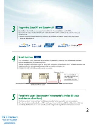
Up to 16 actuator axes can be operated with a XSEL controller program, with the XSEL controller acting as the master and
each ROBO Cylinder controller as a slave.
One of the following two methods can be selected for communication among the controllers.
Type Comm. method Comm. speed How to use
DeviceNet
specification DeviceNet 500 kbps
The DeviceNet Gateway master board must be installed in an I/O slot of
the XSEL controller.
Specify “DG” as the I/O slot type for the XSEL controller.
SIO
specification RS232C 230.4kbps
Use the 2-channel communication port (standard equipment) of
the XSEL controller.
To connect slave controllers, the dedicated 2-channel connection port
cable is needed. (Model: CB-RS-SIO005, length 0.5 m)
* Contact us for the wiring and setting methods for the RC Gateway function.
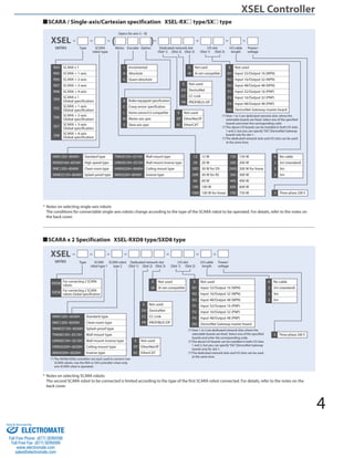
Features
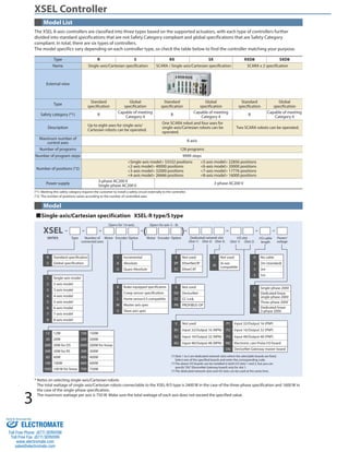
Controller type R type RX/RXD8 type S type SX/SXD8 type
Applicable motor output 12W to 750W
Number of control axes 1 to 8 axes
Maximum connected
axes output
[Three-phase specification]
2400W max.
[Single-phase specification]
1600W max.
[Three-phase specification]
2400W max.
[Three-phase specification]
2400W max.
[Single-phase specification]
1600W max.
[Three-phase specification]
2400W max.
Control power-supply input Single-phase AC200/230V ± 10%
Power supply frequency 50/60 Hz
Insulation resistance 10 MΩ or more (500-VDC reading between the power-supply terminal and I/O terminal, and between all external terminals and the case)
Withstand voltage AC1500V (1 minute)
Power-supply capacity (max.) 5094 VA (at the maximum output of connected axes)
Position detection method Only incremental/absolute encoders of serial communication type are supported (for all axes).
Safety circuit configuration Redundancy not supported Double Redundant Enabled
Drive source breaker system Internal cutoff relay External safety circuit
Emergency stop input B Contact Input (Internal Power Supply Model) B Contact Input (External Power Supply Model, Double Redundant)
Enable input B Contact Input (Internal Power Supply Model) B Contact Input (External Power Supply Model, Double Redundant)
Speed setting 1 mm/sec and up, the maximum depends on the actuator specifications
Acceleration/
Deceleration setting 0.01 G and up, the maximum depends on the actuator specifications
Programming language Super SEL language
Number of programs 128 programs
Number of program steps 9999 steps (total)
Number of multi-tasking
programs 16 programs
Number of positions Varies depending on the number of controlled axes. 6 axes: 20000 positions, 8 axes: 16000 positions (total)
Data memory device Flash ROM + non-volatile RAM (FRAM): System battery (button battery) not required
Data input method Teaching pendant or PC
Standard input/output 2 boards can be installed, including a PIO board of 48 I/O points (NPN/PNP) and a PIO board of 96 I/O points (NPN/PNP)
Expansion input/output None (A separate expansion I/O unit can be used to add up to 4 PIO boards.)
Serial communications
function Teaching port (D-sub 25 pins), 2-channel RS232C ports (D-sub 9 pins) Baud rate: 115.2 kbps max.
IA net Number of connected units: 64 controllers / Baud rate: 12 Mbps, fixed
RC Gateway function RS232C communication port (Channel 2 only) or DeviceNet Gateway master board port.
Fieldbus communication
DeviceNet, CC-LINK, Profibus, EtherNet/IP, EtherCAT
function
(One of EtherNet/IP and EtherCAT, and one of DeviceNet, CC-LINK and Profibus, can be supported at the same time.)
Clock function Retention time: Approx. 10 days Charge time: Approx. 100 hours
Display unit Optional panel unit (PU-1) can be connected.
Regenerative resistance Built-in regenerative resistor of 1 kΩ/20 W (External regenerative resistor unit(s) can be connected.)
Absolute battery AB-5 (built into the controller)
Protection function Motor overcurrent, overload, motor driver temperature check, overload check, encoder open-circuit check, soft limit over, system error,
battery error, etc.
Ambient operating temp/
humidity 0 to 40°C, 85% RH or less (non-condensing). Free from corrosive gases. In particular, there shall be no significant dust.
* Refer to the operation manual or contact us for the power-supply capacity, etc.
XSEL Controller
Specification Table
6
Sold Serviced By:
ELECTROMATE
Toll Free Phone (877) SERVO98
Toll Free Fax (877) SERV099
www.electromate.com
sales@electromate.com](https://image.slidesharecdn.com/iaixselrsspecsheet-141015201901-conversion-gate01/85/Iai-xsel-r_s_specsheet-7-320.jpg)
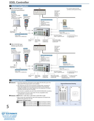
![CJ0197-1A-USA-1-0313
Front view
External Dimensions
186
186
186
186
186
186
Note that the models specified below cannot be operated with the XSEL-R/RX/S/SX types.
Linear servo actuators (other than the LSAS Series), RCS2-5N, RCS2-SRA7BD/SRGS7BD/SRGD7BD, NS-SXM/SZM
(all incremental specifications only)
With the XSEL-RX/SX types, the conditions for connectable single-axis/Cartesian robots vary depending on the SCARA robot
to be connected. For details, refer to the table below.
SCARA robot model Single-axis robot conditions
IX-NNN1205/1505/1805
1500W max. as the total of 4 axes, 750W max. per axis
IX-NNN2515H/3015H/3515H
IX-NNN50H60H 600W max. as the total of 4 axes, 600W max. per axis
IX-NNN70H80H
Connection not possible
IX-NSN5016H/6016H
*The same SCARA robot models apply to wall-mounted, ceiling, clean room and splash-proof specifications.
Side view
Incremental specification Absolute specification
R
RX
RXD
(Note 1)
3-phase
Single-phase
(Common)
S
SX
SXD
(Note 1)
3-phase
Single-phase
358
374
180
195
59 120 120 59
5
3-ø5
358
402
180
195
59 120 120 59
5
3-ø5
(36)
125.3
(80)
315 3
331
180
195
57.5 100 100 57.5
5
3-ø5
315
359
180
195
57.5 100 100 57.5
5
3-ø5
(36)
358
374
180
195
59 120 120 59
5
3-ø5
358
402
180
195
59 120 120 59
5
3-ø5
(36)
(Note 1) If any one of the connected axes is of absolute specification, the external dimensions for absolute specification shall apply.
Note, however, that the external dimensions for incremental specification shall apply to SCARA robots of RX4/SX4/RXD8/SXD8 types because the battery is
installed in the SCARA robot.
If axes for RX/SX other than SCARA robots are of absolute specification, the external dimensions for absolute specification shall apply.
Notes on Using Controllers
With the XSEL-RXD/SXD types, some combinations do not permit the second SCARA robot to be connected
depending on the type of the first SCARA robot connected. For details, refer to the table below.
SCARA robot [1] model Models connectable as SCARA robot [2]
IX-NNN1205/1505/1805 IX-NNN1205/1505/1805/2515H/3015H/3515H/50H/60H
IX-NNN2515H/3015H/3515H IX-NNN1205/1505/1805/2515H/3015H/3515H
IX-NNN50H/60H IX-NNN1205/1505/1805
*The same SCARA robot models apply to wall-mounted, ceiling, clean room and splash-proof specifications.
*Types larger than the IX-NNN70 cannot be operated with the RXD8/SXD8.
Sold Serviced By:
ELECTROMATE
Toll Free Phone (877) SERVO98
Toll Free Fax (877) SERV099
www.electromate.com
sales@electromate.com](https://image.slidesharecdn.com/iaixselrsspecsheet-141015201901-conversion-gate01/85/Iai-xsel-r_s_specsheet-8-320.jpg)

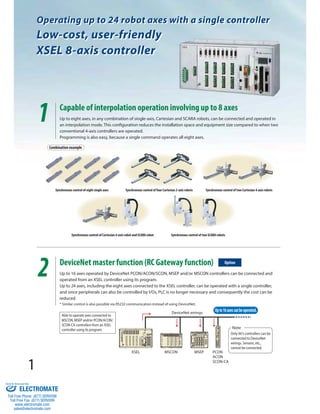
This document provides specifications for the XSEL Series 8-axis program controller sold by Electromate. It can operate up to 24 robot axes with a single controller by interpolating up to 8 axes or connecting additional controllers via DeviceNet, EtherCAT, or EtherNet/IP. It also allows networking multiple XSEL controllers via IA net for expanded I/O and monitoring capabilities. The controller includes maintenance functions to count axis movements and notify when servicing is required.


