This document discusses a proposed sailing robot that can be controlled remotely using RF wireless communication. The robot would use sensors like depth sensors, obstacle sensors, and metal detectors to perform tasks like measuring ocean depths and locating sunken ships. It would also use a GPS module for navigation and tracking and a camera to send video back to the controller. The robot's movements would be controlled from a laptop using an RF module, and sensor data would also be transmitted back to the laptop. The goal is to develop a robot that can perform dangerous oceanic missions without risking human lives onboard.
solar power satellite & microwave power transmissionbhavisha patel
In this seminar topic,I included all the things related SPS system & how microwave power transmission can done through magetron,retro directive beam controlling scheme & all.I also mentioned the design of optical rectenna & economic evolution of the topic.
Space-based solar power is the concept of collecting solar power in space for use on Earth. It has been in research since the early 1970s.
SBSP would differ from current solar collection methods in that the means used to collect energy would reside on an orbiting satellite instead of on Earth's surface.
Process:
A means of collecting solar power in space.
A means of transmitting power to earth.
A means of receiving power on earth.
Wireless power transmission via Space Based Solar Powernikhil gaurav
this presentation tells about how the power is transmitting wireless and how it helps to decrease the losses in power transmission and thus increases efficiency and more important is uses a renewable source of energy(SUN).
A Presentation on Space Based Solar Power and the Different models proposed by some countries. Technological aspect and the future of Energy in the Global Scenario. Renewable Energy
A presentation on upcoming Solar Power Technologies as a viable means of efficiently harnessing solar energy. Part of Self Study Phase-2 at RV College of Engineering, Bangalore.
Part 1 is here: http://www.slideshare.net/Jayanth-R/solar-power-satellites
This paper is all about how to install solar power stations in space and collecting solar energy with an efficiency of 95% (as proven). And then by using either microwaves or LASER, sending that energy to the power grids on earth and converting it into electricity.
future generation there may will be energy crises.
so to avoid these we are going for the technology named solar power plant through space satellite which provides continuous power supply . still research is going on this topic
S&A CW-3000 series thermolysis type water cooler has compact design,with energy saving,high cost performance,good protection and alarm system. It’s mainly used on the equipment for heat exchange between the heat and the air environment. The water temperature of cw-3000 cooler is related to ambient temperature, so it's thermostat is not manually adjusted.
Features:
1. Radiating capacity: 50W / ℃;
2. Small thermolysis water cooler, energy saving, long working life and simple operation;
3. With completed water flow and over high temperature alarm functions;
4. Multiple power specifications; CE approval; RoHS approval;
project presentation on cell phone operated land roversunanda kothari
The objective of this project is to enable the users to control a robot by a mobile phone that makes a call to the mobile phone attached to the robot. The operations performed by the cell phone operated land rover includes forward, backward, stop, left and right turn.
In this paper, we present the idea of sun based vitality satellites sun oriented cells in the satellite Convert daylight into power, which will transform into radio recurrence vitality, at that point a collector will achieve the site Earth was re jolted by utilizing the reception apparatus with the innovation of remote and accepting it Power transmission is transmitting power i.e., as microwave for lessening transmission and dispersion. In this paper we want to elaborate all the aspect related to the wireless power transmission using solar power satellite by which the overall efficiency, reliability will be increased. Karan Sharma | Prateeek Saini | Naveen Jangid | Dr. Himani Goyal Sharma ""Wireless Power Transmission using SPS"" Published in International Journal of Trend in Scientific Research and Development (ijtsrd), ISSN: 2456-6470, Volume-3 | Issue-3 , April 2019, URL: https://www.ijtsrd.com/papers/ijtsrd21719.pdf
Paper URL: https://www.ijtsrd.com/engineering/electrical-engineering/21719/wireless-power-transmission-using-sps/karan-sharma
Transmission of Wireless Power using Solar Power satellite Technologyijtsrd
As we know that Sun is the great source of energy on the earth & we cant even imagine the life of any living organisms on the earth .Energy can be produced in three modes 1.Induction(In which two bodies are not connected together but even there is requirement of medium ) 2. Conduction (In which bodies are in contact with each other & it also requires medium) 3.Radiation(In which there is no contact of bodies but energy transmitted in form of photons). Solar energy is radiant light & heat from the Sun that is harnessed using a range of ever-evolving technologies such as solar heating ,photovoltaic, solar thermal energy .It is an important source of renewable energy and its technologies are broadly characterized as either passive solar or active solar on how they capture and distribute solar energy or convert it into solar power. Wireless Power transmission (WPT) is a useful and convenient technology that can be employed to collect solar energy and concentrate on earth surface without the need for a wire connection called a solar power satellites (SPS). This paper provides an analysis of wireless power transfer with an assessment of its practical applicability in terms of power range and efficiency. In this paper, various technologies available so far for wireless transmission of electricity and the need for a Wireless Energy Transmission will be discussed to find its possibility in actual practices. Also, their advantages, disadvantages and economical consideration will also be presented. This paper concentrates mainly on (i) The most popular concept known as Tesla Theory, (ii) The microwave power transmission(MPT) called Solar power satellite, and (iii) The highly efficient fibre lasers for wireless power transmission. Many concepts, research papers, and patents are available on wireless transmission of electricity but the commercial technologies are yet to be materialized. This paper will also discuss the possible ways to get useful and practical results out of all researches carried out so far elsewhere. The output microwave power ranges from 50W to 200W at 2.45GHz. A coaxial cable is to connect the output of the microwave source to a coax-to-waveguide adapter. This adapter is connected to a waveguide ferrite circulator which protects the microwave source from reflected power. The circulator is connected to a tuning waveguide section to match the waveguide impedance to the antenna input impedance. Kunwar Rajesh | Ranjan Kumar Singh"Transmission of Wireless Power using Solar Power satellite Technology" Published in International Journal of Trend in Scientific Research and Development (ijtsrd), ISSN: 2456-6470, Volume-2 | Issue-4 , June 2018, URL: http://www.ijtsrd.com/papers/ijtsrd13068.pdf http://www.ijtsrd.com/engineering/electronics-and-communication-engineering/13068/transmission-of-wireless-power-using-solar-power-satellite-technology/kunwar-rajesh
Introduction to Satellite Power Station, Need for SPS, Basic Components of SPS and their description, Challenges, Present Status and future expectation.
iaetsd Modeling of solar steam engine system using parabolic
Iaetsd rf controlled sailing robot for oceanic missions
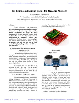
1. RF Controlled Sailing Robot for Oceanic Missions
R. Srikanth Kumar1
, K. Dhanunjaya2
1
PG Student, Department of ECE, ASCET, Gudur, Andhra Pradesh, India
2
Head of the Department, Department of ECE, ASCET, Gudur, Andhra Pradesh, India
Abstract:
Ocean exploration and navigational
research by supporting expeditions with computer
vision techniques have shown potential for sailing
robots development in order to make
measurements at the surface. Sailing robots
explores the science and technologies for the
identification of underwater features. Key
applications of sailing robot are measuring depth
and sensing metals under the water. An idea
presented is the robot that can sail on water,
controlled by laptop keypad. Other modules are
gps and camera.
Keywords: sailing robot, laptop, gps, camera
I. INTRODUCTION
For oceanic missions such as finding metals,
spy applications, measuring depth, etc., one has to
travel on the boat. But it is risky, because climate can
change suddenly on the ocean. For example cyclone
may occur suddenly. Also while spying, the opposite
one may fire and can result in death of driver
controlling the boat.
To overcome this, the boat has to be
designed in such a way that it can be operated
without a driver. So it has to use any means of
wireless communications. In this paper RF pro
wireless communication is presented.
II. RF WIRELESS COMMUNICATION
The commands for respective movements of
sailing robot are send from laptop keypad through RF
PRO wireless communication. The module used for
this purpose is RFSv4.3. It provides easy and flexible
wireless data transmission between devices. RFSv4.3
uses 2.4 GHz carrier frequency. On pressing keys on
laptop keypad respective action takes place. For
example on pressing 1 the sailing robot moves
forward. For this project two RFSv4.3 modules are
necessary. The data received from sensors is also
transmitted to laptop through these modules.
III. SENSORS
A. Depth sensor:
One of the applications of sailing
robot is to measure depth under water. For this an
ultrasonic sensor is used. The module used is
Ultrasonic ranging module HC-SR04. The basic
principle depends on echo reception. A short 10s
pulse is supplied to the trigger input. The module will
send out an 8 cycle burst of ultrasound at 40 KHz.
After hitting ground the pulse signal is reflected back.
Now the range can be calculated through the time
interval between sending trigger signal and receiving
echo signal. The formula is,
Distance = (time taken × velocity of sound)/2
Proceedings of International Conference on Developments in Engineering Research
ISBN NO : 378 - 26 - 13840 - 9
www.iaetsd.in
INTERNATIONAL ASSOCIATION OF ENGINEERING & TECHNOLOGY FOR SKILL DEVELOPMENT
58
2. B. Obstacle Sensor:
Although the sailing robot is
monitored through camera, there may be chances of
collision with obstacles because of controller
inactive. So to avoid this an ultrasonic sensor is used
to detect the obstacles. When an obstacle is detected
the sailboat automatically stops.
C. Metal sensor:
To detect metals under the water, a
metal sensor is used. The metal sensor used is ID18 –
3008NA. It is water proof. This module is useful in
finding missing ships.
IV. GPS
As the climate on ocean is
unpredictable, there is a chance of missing of
sailboat. This may occur because of cyclone or some
other reasons. So a GPS module is used to detect the
sailboat when missed. The GPS module used is
Royaltek REB-1315S4. GPS module can also be used
for navigation purpose.
V. CAMERA
This module sends continuous
video to the laptop for continuous monitoring. The
camera used in this project can send video from 50 to
100 meters distance if it in line of sight with receiver.
This can also be used for spy applications.
VI. X-CTU TERMINAL
All the values received from
sensors can be displayed on laptop using X-CTU
terminal.
VII. REFERENCES
1. www.google.com
2. www.keil.com
3. www.nxp.com
4. www.robosoftsystems.co.in
5. www.royaltek.com
6. www.ideal.net.in
Proceedings of International Conference on Developments in Engineering Research
ISBN NO : 378 - 26 - 13840 - 9
www.iaetsd.in
INTERNATIONAL ASSOCIATION OF ENGINEERING & TECHNOLOGY FOR SKILL DEVELOPMENT
59
3. Solar Power Satellites
K. Deepak K. Poojitha
IV B.Tech EIE IV B.Tech EIE
Sree Vidyanikethan Engineering College Sree Vidyanikethan Engineering College
Abstract
Solar Power Satellites (SPS)
converts solar energy in to micro waves
and sends that microwaves in to a beam to
a receiving antenna on the Earth for
conversion to ordinary Electricity. SPS is
a clean, large-scale, stable electric power
source. For SPS Wireless power
transmission is essential. WPT contains
microwave beam, which can be directed to
any desired location on Earth surface. This
beam collects Solar Energy and converts it
into Electrical Energy. This concept is
more advantageous than conventional
methods. The SPS will be a central
attraction of space and energy technology
in coming decades. It is not a pollutant but
more aptly, a man made extension of the
naturally generated electromagnetic
spectrum that provides heat and light for
our sustenance.
Keywords: Solar Power Satellites;
Microwaves;
1. Introduction
The new millennium has introduced
increased pressure for finding new renewable
energy sources. The exponential increase in
population has led to the global crisis such as
global warming, environmental pollution and
change and rapid decrease of fossil
reservoirs. Also the demand of electric power
increases at a much higher pace than other
energy demands as the world is industrialized
and computerized. Under these
circumstances, research has been carried out
to look in to the possibility of building a
power station in space to transmit electricity
to Earth by way of radio waves-the Solar
Power Satellites. Solar Power Satellites
(SPS) converts solar energy in to micro
waves and sends that microwaves in to a
beam to a receiving antenna on the Earth for
conversion to Ordinary Electricity. SPS is a
clean, large-scale, stable electric power
source. Solar Power Satellites is known by a
variety of other names such as Satellite
Power System, Space Power Station, Space
Power System, Solar Power Station, Space
Solar Power Station etc. One of the key
Technologies needed to enable the future
feasibility of SPS is that of Microwave
Wireless Power Transmission.
WPT is based on the energy transfer
capacity of microwave beam I e, energy can
be transmitted by a well-focused microwave
beam. Advances in Phased array antennas
and rectennas have provided the building
blocks for a realizable WPT system
1.1 Why SPS
Increasing global energy demand is
likely to continue for many decades.
Renewable energy is a compelling approach
– both philosophically and in engineering
terms. However, many renewable energy
sources are limited in their ability to
affordably provide the base load power
required for global industrial development
and prosperity, because of inherent land and
water requirements. The burning of fossil
fuels resulted in an abrupt decrease in their
availability. It also led to the green-house
effect and many other environmental
Proceedings of International Conference on Developments in Engineering Research
ISBN NO : 378 - 26 - 13840 - 9
www.iaetsd.in
INTERNATIONAL ASSOCIATION OF ENGINEERING & TECHNOLOGY FOR SKILL DEVELOPMENT
60
4. problems. Nuclear power seems to be an
answer for global warming, but concerns
about terrorist attacks on Earth bound nuclear
power plants have intensified
environmentalist opposition to nuclear
power. Earth based solar panels receives only
a part of the solar energy. So it is desirable to
place the solar panel in the space itself,
where, the solar energy is collected and
converted in to electricity which is then
converted to a highly directed microwave
beam for transmission. This microwave
beam, which can be directed to any desired
location on Earth surface, can be collected
and then converted back to electricity. This
concept is more advantageous than
conventional methods. Also the microwave
energy, chosen for transmission, can pass
unimpeded through clouds and
precipitations.
1.2 SPS –The Background
The concept of a large SPS that would
be placed in geostationary orbit was invented
by Peter Glaser in 1968.The SPS concept was
examined extensively during the late 1970s
by the U.S Department of Energy (DOE) and
the National Aeronautics and Space
Administration (NASA). The DOE-NASA
put forward the SPS Reference System
Concept in 1979. The central feature of this
concept was the creation of a large scale
power infrastructure in space, consisting of
about 60 SPS, delivering a total of about
300GW.But, as a result of the huge price tag,
lack of evolutionary concept and the
subsiding energy crisis in 1980-1981, all U.S
SPS efforts were terminated with a view tore-
asses the concept after about ten years.
During this time international interest in SPS
emerged which led to WPT experiments in
Japan.
1.3 SPS-A General Idea
Solar Power Satellites would be
located in the geo-synchronous orbit. The
difference between existing satellites and
SPS is that an SPS would generate more
power-much more power than it requires for
its own operation. The solar energy collected
by an SPS would be converted into
electricity, then into microwaves. The
microwaves would be beamed to the Earth’s
surface, where they would be received and
converted back into electricity by a large
array of devices known as rectifying antenna
or rectennas.
Each SPS would have been massive;
measuring 10.5 km long and 5.3km wide or
with an average area of 56 sq. km. The
surface of each satellite would have been
covered with 400 million solar cells. The
transmitting antenna on the satellite would
have been about 1 km in diameter and the
receiving antenna on the Earth’s surface
would have been about 10 km in diameter. In
order to obtain a sufficiently concentrated
beam; a great deal of power must be collected
and fed into a large transmitter array. The
power would be beamed to the Earth in the
form of microwave at a frequency of 2.45
GHz. Microwaves have other features such as
larger band width, smaller antenna size, sharp
radiated beams and they propagate along
straight lines.
Microwave frequency in the range of
2-3 GHz are considered optimal for the
transmission of power from SPS to the
ground rectennas site.The amount of power
available to the consumers from one SPS is
5GW. The peak intensity of microwave beam
would be 23 m W/cm². SPS has all the
advantage of ground solar, it generates power
during cloudy weather and at night. In other
words
SPS receiver operates just like a solar
array. It receives power from space and
converts it into electricity. This reduces the
size and complexity of satellite.
Proceedings of International Conference on Developments in Engineering Research
ISBN NO : 378 - 26 - 13840 - 9
www.iaetsd.in
INTERNATIONAL ASSOCIATION OF ENGINEERING & TECHNOLOGY FOR SKILL DEVELOPMENT
61
5. Fig1: Basic Design Of SPS
2. Wireless Power Transmission
Transmission or distribution of 50 or
60 Hz electrical energy from the generation
point to the consumer end without any
physical wire has yet to mature as a familiar
and viable technology. The 50 Hz ac power
tapped from the grid lines is stepped down to
a suitable voltage level for rectification into
dc. This is supplied to an oscillator fed
magnetron.
The microwave power output of the
magnetron is channeled into an array of
parabolic reflector antennas for transmission
to the receiving end antennas. To compensate
for the large loss in free space propagation
and boost at the receiving end the signal
strength as well as the conversion Efficiency,
the antennas are connected in arrays. A
simple radio control feedback system
operating in FM band provides an
appropriate control signal to the magnetron
for adjusting its output level with fluctuation
in the consumers demand at the receiving
side. The overall efficiency of the WPT
system can be improved by-Increasing
directivity of the antenna array. Using dc to
ac inverters with higher conversion
efficiency .Using schottky-diode with higher
ratings.
2.1 Microwave Power Transmission In
SPS
The microwave transmission system
have had three aspects:
1. The conversion of direct power from the
photovoltaic cells, to microwave power on
the satellites on geosynchronous orbit above
the Earth.
2. The formation and control of microwave
beam aimed precisely at fixed locations on
the Earth’s surface.
3. The collection of the microwave energy
and its conversion into electrical energy at the
earth’s surface.
The key microwave components in a
WPT system are the transmitter, beam
control and the receiving antenna called
rectennas. At the transmitting antenna,
microwave power tubes such as magnetrons
and klystrons are used as RF power sources.
Rectenna is a component unique to WPT
systems. The following section describes
each of these components in detail.
2.2 Transmitter
The key requirement of a transmitter
is its ability to convert dc power to RF power
efficiently and radiate the power to a
controlled manner with low loss. The
transmitter’s efficiency drives the end-to-end
efficiency as well as thermal management
system. The main components of a
transmitter include dc-to-RF converter and
transmitting antenna. Power distribution at
the transmitting antenna = (1-r²), where r is
the radius of antenna [7].There are mainly
three dc-to-RF power converters:
magnetrons, klystrons and solid state
amplifiers.
Fig. 2: Klystron amplifier
Proceedings of International Conference on Developments in Engineering Research
ISBN NO : 378 - 26 - 13840 - 9
www.iaetsd.in
INTERNATIONAL ASSOCIATION OF ENGINEERING & TECHNOLOGY FOR SKILL DEVELOPMENT
62
6. Klystron
Fig. 2 shows the klystron amplifier [15]. Here
a high velocity electron beam is formed,
focused and send down a glass tube to a
collector electrode which is at high positive
potential with respect to the cathode. As the
electron beam having constant velocity
approaches gap A, they are velocity
modulated by the RF voltage existing across
this gap. Thus as the beam progress further
down the drift tube, bunching of electrons
takes place. This variation in current enables
the klystron to have significant gain. Thus the
catcher cavity is excited into oscillations at its
resonant frequency and a large output is
obtained.
The tube body and solenoid operate at
300°C and the collector operates at 500°C.
The overall efficiency is 83%. The
microwave power density at the transmitting
array will be 1 kW/m² for a typical 1 GW SPS
with a transmitting antenna aperture of 1 km
diameter. If we use 2.45 GHz for MPT, the
number of antenna elements per square meter
is on the order of 100.
2.3 Rectenna
Brown was the pioneer in developing the first
2.45GHz rectenna. Rectenna is the
microwave to dc converting device and is
mainly composed of a receiving antenna and
a rectifying circuit. Fig .4 shows the
schematic of rectenna circuit. It consists of a
receiving antenna, an input low pass filter, a
rectifying circuit and an output smoothing
filter. The input filter is needed to suppress
radiation of high harmonics that are
generated by the non-linear characteristics of
rectifying circuit. Because it is a highly non-
linear circuit, harmonic power levels must be
suppressed.
Fig. 3: Schematic of rectenna circuit.
For rectifying Schottky barrier diodes
utilizing silicon and gallium arsenide are
employed. Diode selection is dependent on
the input power levels. The breakdown
voltage limits the power handling capacity
and is directly related to series resistance and
junction capacitance through the intrinsic
properties of diode junction and material. For
efficient rectification the diode cut off
frequency should be approximately ten times
the operating frequency.
Diode cut off frequency is given by ƒ=1/
[2_RsCj], where ƒ is the cut off frequency, Rs
is the diode series resistance, Cj is the zero-
bias junction capacitance.
2.5 Recently Developed MPT Systems
The Kyoto University developed a
system called Space Power Radio
Transmission System (SPORTS).The
SPORTS is composed of solar panels, a
microwave transmitter subsystem, a near
field scanner, a microwave receiver. The
solar panels provide 8.4 kW dc power to the
microwave transmitter subsystem composed
of an active phased array. It is developed to
simulate the whole power conversion process
for the SPS, including solar cells,
transmitting antennas and rectenna system.
Another MPT system recently developed by
a team of Kyoto University, NASDA and
industrial companies of Japan, is an
integrated unit called the Solar Power Radio
Integrated Transmitter (SPRITZ), developed
in 2000. This unit is composed of a solar cell
panel, microwave generators, transmitting
Proceedings of International Conference on Developments in Engineering Research
ISBN NO : 378 - 26 - 13840 - 9
www.iaetsd.in
INTERNATIONAL ASSOCIATION OF ENGINEERING & TECHNOLOGY FOR SKILL DEVELOPMENT
63
7. array antennas and a receiving array in one
package.
3. Construction of SPS from Non
Terrestrial Materials: Feasibility and
Economics
SPS, as mentioned before is massive
and because of their size they should have
been constructed in space. The aluminum and
silicon can be refined to produce solar arrays.
Among them are the shallow gravity wells of
the Moon and asteroids; the presence of an
abundance of glass, metals and oxygen in the
Apollo lunar samples; the low cost transport
of those materials to a higher earth orbit by
means of a solar powered electric motor; the
availability of continuous solar energy for
transport, processing and living. One major
new development for transportation is
required: the mass driver. The mass driver is
a long and narrow machine which converts
electrical energy into kinetic energy by
accelerating 0.001 to 10 kg slugs to higher
velocities. The mass driver conversion
efficiency from electrical to kinetic energy is
close to 100 percent.
3.1 Microwaves-Environmental Issues
The price of implementing a SPS
includes the acceptance of microwave beams
as the link of that energy between space and
earth. Because of their large size, SPS would
appear as a very bright star in the relatively
dark night sky. SPS possess many
environmental questions such as microwave
exposure, optical pollution that could hinder
astronomers, the health and safety of space
workers in a heavy-radiation (ionizing)
environment, the potential disturbance of the
ionosphere etc. The atmospheric studies
indicate that these problems are not
significant, at least for the chosen microwave
frequency.
On the earth, each rectenna for a full-
power SPS would be about 10 km in
diameter. This significant area possesses
classical environmental issues. These could
be overcome by sitting rectenna in
environmentally insensitive locations, such
as in the desert, over water etc. However, the
issues related to microwaves continue to be
the most pressing environmental issues. On
comparing with the use of radar, microwave
ovens, police radars, cellular phones and
wireless base stations, laser pointers etc.
public exposures from SPS would be similar
or even less. Based on well-developed
antenna theory, the environmental levels of
microwave power beam drop down to
0.1ìW/cm².
Serious discussions and education are
required before most of mankind accepts this
technology with global dimensions.
Microwaves, however is not a ‘pollutant’ but,
more aptly, a man made extension of the
naturally generated electromagnetic
spectrum that provides heat and light for our
substance.
4. Advantages and Disadvantages
The idea collecting solar energy in
space and returning it to earth using
microwave beam has many attractions. The
full solar irradiation would be available at all
times expect when the sun is eclipsed by the
earth. Thus about five times energy could be
collected, compared with the best terrestrial
sites. The power could be directed to any
point on the earth’s surface. The zero gravity
and high vacuum condition in space would
allow much lighter, low maintenance
structures and collectors. The power density
would be uninterrupted by darkness, clouds,
or precipitation, which are the problems
encountered with earth based solar arrays.
The realization of the SPS concept holds
great promises for solving energy crisis.
The concept of generating electricity
from solar energy in the space itself has its
inherent disadvantages also.
Proceedings of International Conference on Developments in Engineering Research
ISBN NO : 378 - 26 - 13840 - 9
www.iaetsd.in
INTERNATIONAL ASSOCIATION OF ENGINEERING & TECHNOLOGY FOR SKILL DEVELOPMENT
64
8. Some of the major disadvantages are:
The main drawback of solar energy
transfer from orbit is the storage of electricity
during off peak demand hours. The frequency
of beamed radiation is planned to be at 2.45
GHz and this frequency is used by
communication satellites also. The entire
structure is massive. High cost and require
much time for construction. Radiation
hazards associated with the system. Risks
involved with malfunction. High power
microwave source and high gain antenna can
be used to deliver an intense burst of energy
to a target and thus used as a weapon.
5. Conclusion and Future Scope
The SPS will be a central attraction of
space and energy technology in coming
decades. However, large scale retro directive
power transmission has not yet been proven
and needs further development. Another
important area of technological development
will be the reduction of the size and weight of
individual elements in the space section of
SPS. Large-scale transportation and robotics
for the construction of large-scale structures
in space include the other major fields of
technologies requiring further developments.
The electromagnetic energy is a tool to
improve the quality of life for mankind. It is
not a pollutant but more aptly, a man made
extension of the naturally generated
electromagnetic spectrum that provides heat
and light for our sustenance. From this view
point, the SPS is merely a down frequency
converter from the visible spectrum to
microwaves.
References-
[1] Hiroshi Matsumoto, “Research on solar
power satellites and microwave power
transmission in Japan”, IEEE microwave
magazine, pp.36-45, Dec 2002.
[2] James O. Mcspadden & John C.
Mankins,”Space solar power programs and
Microwave wireless power transmission
technology”, IEEE microwave magazine,
pp.46-57, Dec 2002.
[3] J.C. Mankins,”A fresh look at space solar
power: new architectures, concepts and
technologies” in 38th Astronautical
Federation.
[4] Seth Potter, “Solar power satellites: an
idea whose time has come [online] Available
on www.freemars.org/history/sps.html, last
updated on Dec.1998
[5] Consumer Energy Information: EREC
Reference Briefs [online] Available on
www.eere.gov/consumerinfo/rebriefs/123.ht
ml,last updated on Apr.03.
[6] Mc GrawHill Encyclopedia of Science
and Technology, vol.16, pp.41.
Proceedings of International Conference on Developments in Engineering Research
ISBN NO : 378 - 26 - 13840 - 9
www.iaetsd.in
INTERNATIONAL ASSOCIATION OF ENGINEERING & TECHNOLOGY FOR SKILL DEVELOPMENT
65