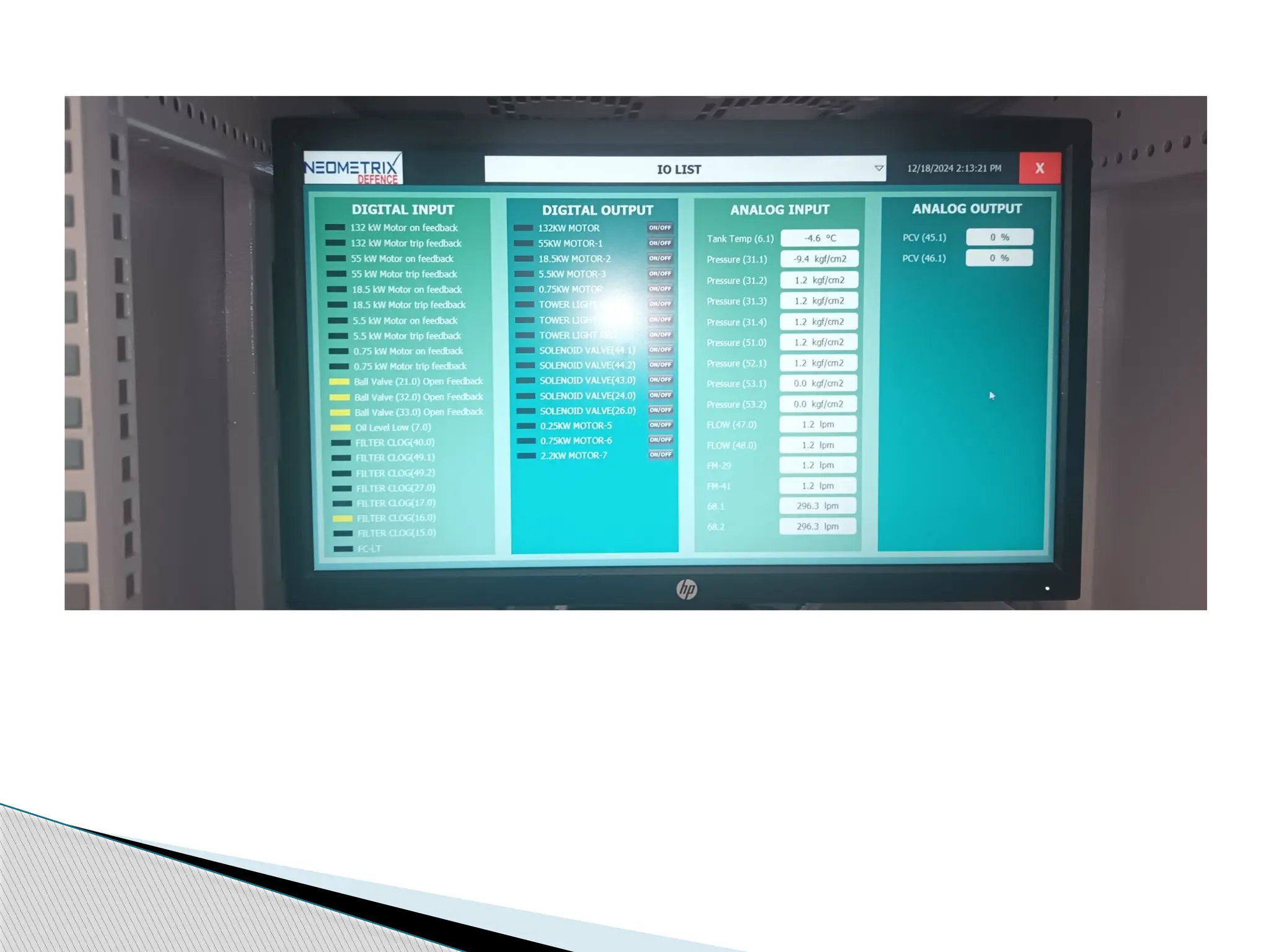
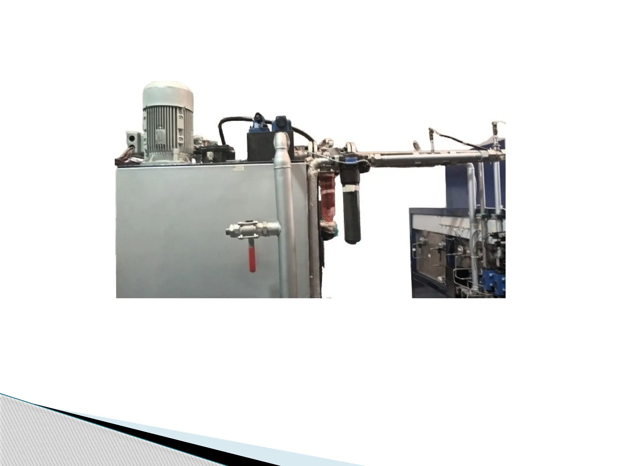
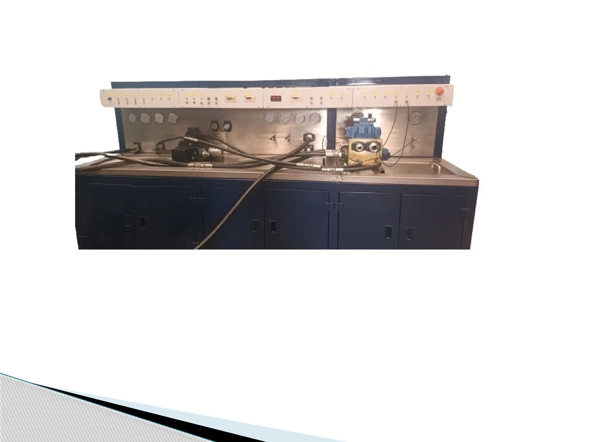
Hydraulic Test Rig
INTRODUCTION
Hydraulic Test Rig has been designed to perform tests on following hydraulic
Components:
• Hydraulic Pumps (Fixed / variable Displacement Piston pumps & Single /
tandem Gear / Vane pumps)
• Hydraulic Motors (Gear / Vane/ Piston Type)
• Pressure control valves.
• Flow control valves.
• Direction control valves.
• Solenoid of DC valves.
• Proportional Control valves.
• Hydraulic Cylinders.
• Check Valves.
 Hydraulic Pumps: The test rig has been designed to test the pump for maximum capacity (flow) of
200 cc/ rev, at 215 bar and internal leakage at rated pressure. Maximum speed of the test motor has been
kept as 1450 rpm. It has been designed to test all the High pressure pump (Fixed/ variable Displacement
Piston pump), Gear pumps, vane pumps listed in Annexure –IA, at their rated flow @ 1450 RPM with
optimum pressure, at rated pressure or maximum test pressure limited to 315bar with optimum RPM
(integrated with VFD starter) and internal leakage at rated pressure with optimum flow.
 Hydraulic Motors: The test rig has been designed to test the Hydraulic motors listed in annexure-IA, at
max pressure 315 bar with optimum flow and at max flow 180 LPM @150 bar through power control
pump motor station, Internal Leakage at rated pressure. Maximum rpm will be 1450.
 Pressure Control Valves: The test rig has been designed to test the Pressure control valve of sizes NG 6
to NG 30 at rated pressure but maximum pressure limited to 315bars with optimum flow for functional
test and internal leakage. Test rig has the capability of testing valves of sizes ranging from NG6 to NG30
using conversion plates
 Flow Control Valves: The test rig has been designed to test the flow control valves of sizes NG 6 to NG 22
at rated pressure but maximum pressure limited to 315 bar with optimum flow, and the functional test
will carried out. Test rig has the capability of testing valves of sizes ranging from NG6 to NG22 using
conversion plates.
 Directional Control Valves: The DC valve of sizes NG 6 to NG 32 at rated pressure but maximum
pressure limited to 315 Bar with optimum flow can be tested for Function and Internal leakage. Test rig
has the capability of testing valves of sizes ranging from NG6 to NG32 using conversion plates.
 Solenoid of DC Valves: An electrical supply line of 24 VDC has been provided for testing the solenoid
valves for their function and continuity.
 Proportional control valves: The valve of sizes NG 6 to NG 32 shall be tested for Flow & pressure at
varying voltage / Current input.
 Hydraulic Cylinders: The test rig has been designed to perform leakage test, rated pressure test,
cushioning test for hydraulic cylinders listed in annexure-IA at maximum 315 bar pressure and at max
flow 180 LPM @ 150 bar through power control pump motor station. Internal leakage test will be carried
out for multi positions (Rod end- Cylinder retracted, Cap end – cylinder extended, rod end
–mid/intermediate stroke, cap end – mid/intermediate stroke). Test Rig is capable to test cylinder with a
maximum stroke of 4.6 meter.
 Check Valves: The test rig has been designed to test cracking pressure and leakage in reverse flow of
check valves.
SYSTEM SPECIFICATIONS
ATF is used as working media for Test equipment for Preliminary Regulation of Aircraft
fuel pump test rig Unit.
Fluid Specifications: - Density (at 15 ºC): 775.0 to 840.0 kg/m3
.
- Kinematic viscosity at minus 20°C, mm2
/s
- Flash point: 38 ºC.
- Temperature of working fluid (ºC): 15 to 40 ºC.
- ATF tank capacity: 100 liters.
Ball Valve: Pressure : UP TO 10 Kgf/cm²
Filter: Filter Rating-16 micron
Non-Return Valve: 10 kgf/cm2
Pump Pressure: 10 kgf/cm2
Motor To Drive Pump: Motor suitable to drive pump(59)Should be flameproof type.
The Test Equipment for Aircraft fuel pump is specifically designed to facilitate the setup and
calibration of the Aircraft fuel pump.
Application
◦ Hydraulic Pumps (Fixed / variable Displacement Piston pumps & Single / tandem Gear /
Vane pumps)
◦ Hydraulic Motors (Gear / Vane/ Piston Type)
◦ Pressure control valves.
◦ Flow control valves.
◦ Direction control valves.
◦ Solenoid of DC valves.
◦ Proportional Control valves.
◦ Hydraulic Cylinders.
◦ Check Valves.
Key Features
Electrical Panel
GA Drawing
Electrical Drawing
Thank You

Hydraulic Test Rig - Neometrix Defence Limited

  • 1.
  • 3.
    INTRODUCTION Hydraulic Test Righas been designed to perform tests on following hydraulic Components: • Hydraulic Pumps (Fixed / variable Displacement Piston pumps & Single / tandem Gear / Vane pumps) • Hydraulic Motors (Gear / Vane/ Piston Type) • Pressure control valves. • Flow control valves. • Direction control valves. • Solenoid of DC valves. • Proportional Control valves. • Hydraulic Cylinders. • Check Valves.
  • 5.
     Hydraulic Pumps:The test rig has been designed to test the pump for maximum capacity (flow) of 200 cc/ rev, at 215 bar and internal leakage at rated pressure. Maximum speed of the test motor has been kept as 1450 rpm. It has been designed to test all the High pressure pump (Fixed/ variable Displacement Piston pump), Gear pumps, vane pumps listed in Annexure –IA, at their rated flow @ 1450 RPM with optimum pressure, at rated pressure or maximum test pressure limited to 315bar with optimum RPM (integrated with VFD starter) and internal leakage at rated pressure with optimum flow.  Hydraulic Motors: The test rig has been designed to test the Hydraulic motors listed in annexure-IA, at max pressure 315 bar with optimum flow and at max flow 180 LPM @150 bar through power control pump motor station, Internal Leakage at rated pressure. Maximum rpm will be 1450.  Pressure Control Valves: The test rig has been designed to test the Pressure control valve of sizes NG 6 to NG 30 at rated pressure but maximum pressure limited to 315bars with optimum flow for functional test and internal leakage. Test rig has the capability of testing valves of sizes ranging from NG6 to NG30 using conversion plates  Flow Control Valves: The test rig has been designed to test the flow control valves of sizes NG 6 to NG 22 at rated pressure but maximum pressure limited to 315 bar with optimum flow, and the functional test will carried out. Test rig has the capability of testing valves of sizes ranging from NG6 to NG22 using conversion plates.
  • 7.
     Directional ControlValves: The DC valve of sizes NG 6 to NG 32 at rated pressure but maximum pressure limited to 315 Bar with optimum flow can be tested for Function and Internal leakage. Test rig has the capability of testing valves of sizes ranging from NG6 to NG32 using conversion plates.  Solenoid of DC Valves: An electrical supply line of 24 VDC has been provided for testing the solenoid valves for their function and continuity.  Proportional control valves: The valve of sizes NG 6 to NG 32 shall be tested for Flow & pressure at varying voltage / Current input.  Hydraulic Cylinders: The test rig has been designed to perform leakage test, rated pressure test, cushioning test for hydraulic cylinders listed in annexure-IA at maximum 315 bar pressure and at max flow 180 LPM @ 150 bar through power control pump motor station. Internal leakage test will be carried out for multi positions (Rod end- Cylinder retracted, Cap end – cylinder extended, rod end –mid/intermediate stroke, cap end – mid/intermediate stroke). Test Rig is capable to test cylinder with a maximum stroke of 4.6 meter.  Check Valves: The test rig has been designed to test cracking pressure and leakage in reverse flow of check valves.
  • 9.
    SYSTEM SPECIFICATIONS ATF isused as working media for Test equipment for Preliminary Regulation of Aircraft fuel pump test rig Unit. Fluid Specifications: - Density (at 15 ºC): 775.0 to 840.0 kg/m3 . - Kinematic viscosity at minus 20°C, mm2 /s - Flash point: 38 ºC. - Temperature of working fluid (ºC): 15 to 40 ºC. - ATF tank capacity: 100 liters. Ball Valve: Pressure : UP TO 10 Kgf/cm² Filter: Filter Rating-16 micron Non-Return Valve: 10 kgf/cm2 Pump Pressure: 10 kgf/cm2 Motor To Drive Pump: Motor suitable to drive pump(59)Should be flameproof type.
  • 11.
    The Test Equipmentfor Aircraft fuel pump is specifically designed to facilitate the setup and calibration of the Aircraft fuel pump. Application
  • 12.
    ◦ Hydraulic Pumps(Fixed / variable Displacement Piston pumps & Single / tandem Gear / Vane pumps) ◦ Hydraulic Motors (Gear / Vane/ Piston Type) ◦ Pressure control valves. ◦ Flow control valves. ◦ Direction control valves. ◦ Solenoid of DC valves. ◦ Proportional Control valves. ◦ Hydraulic Cylinders. ◦ Check Valves. Key Features
  • 13.
  • 14.
  • 15.
  • 16.