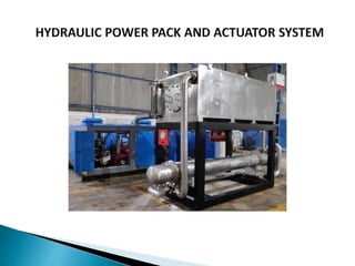
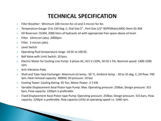
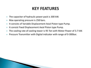
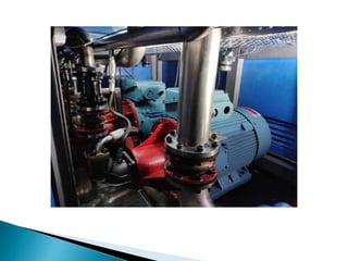
The document discusses the specifications for a hydraulic power supply system. It will include:
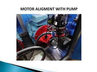
- One variable displacement pump and two fixed displacement pumps
- An electrostatic oil cleaner, cooling tower, dehydration and degasification units
- Sensors to monitor temperature at various points
- An oil reservoir, filters down to 3 microns, and other components
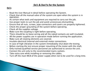
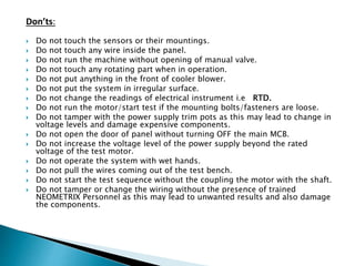
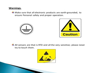
It provides details on operating parameters, components like pumps and heat exchangers, and guidelines for safe operation including dos and don'ts.