Download as PDF, PPTX
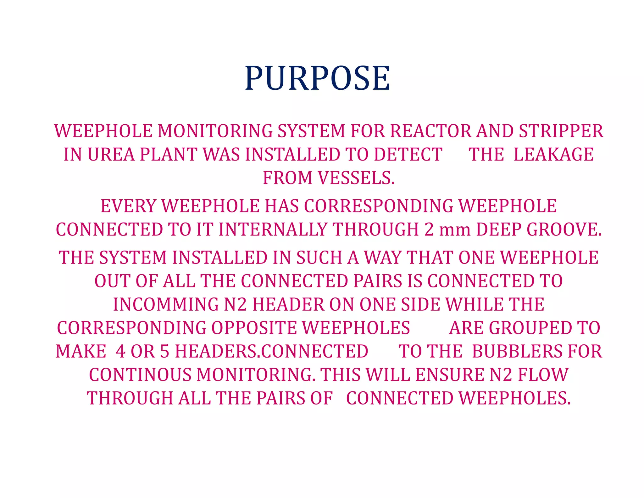
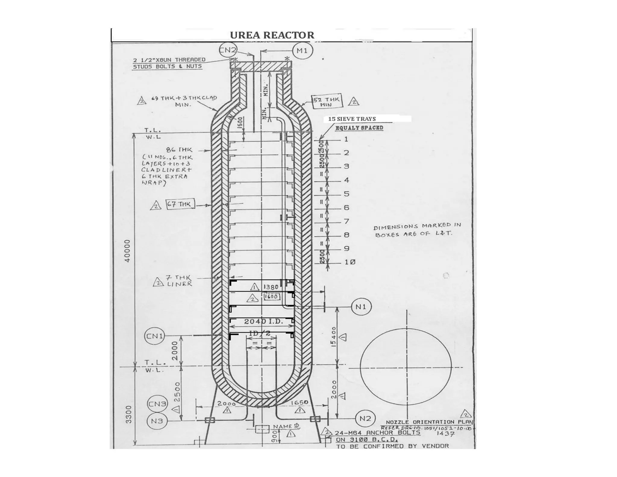
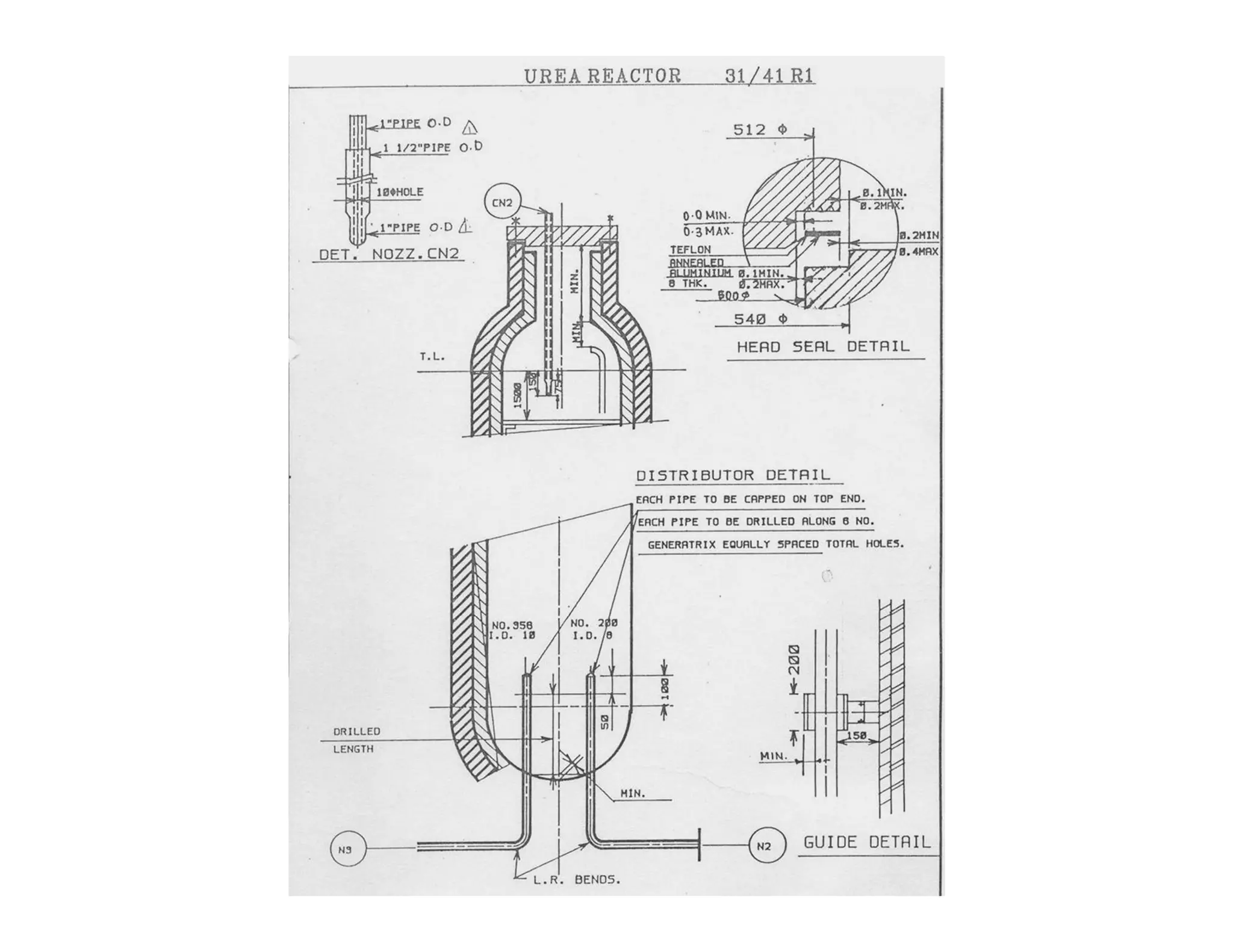
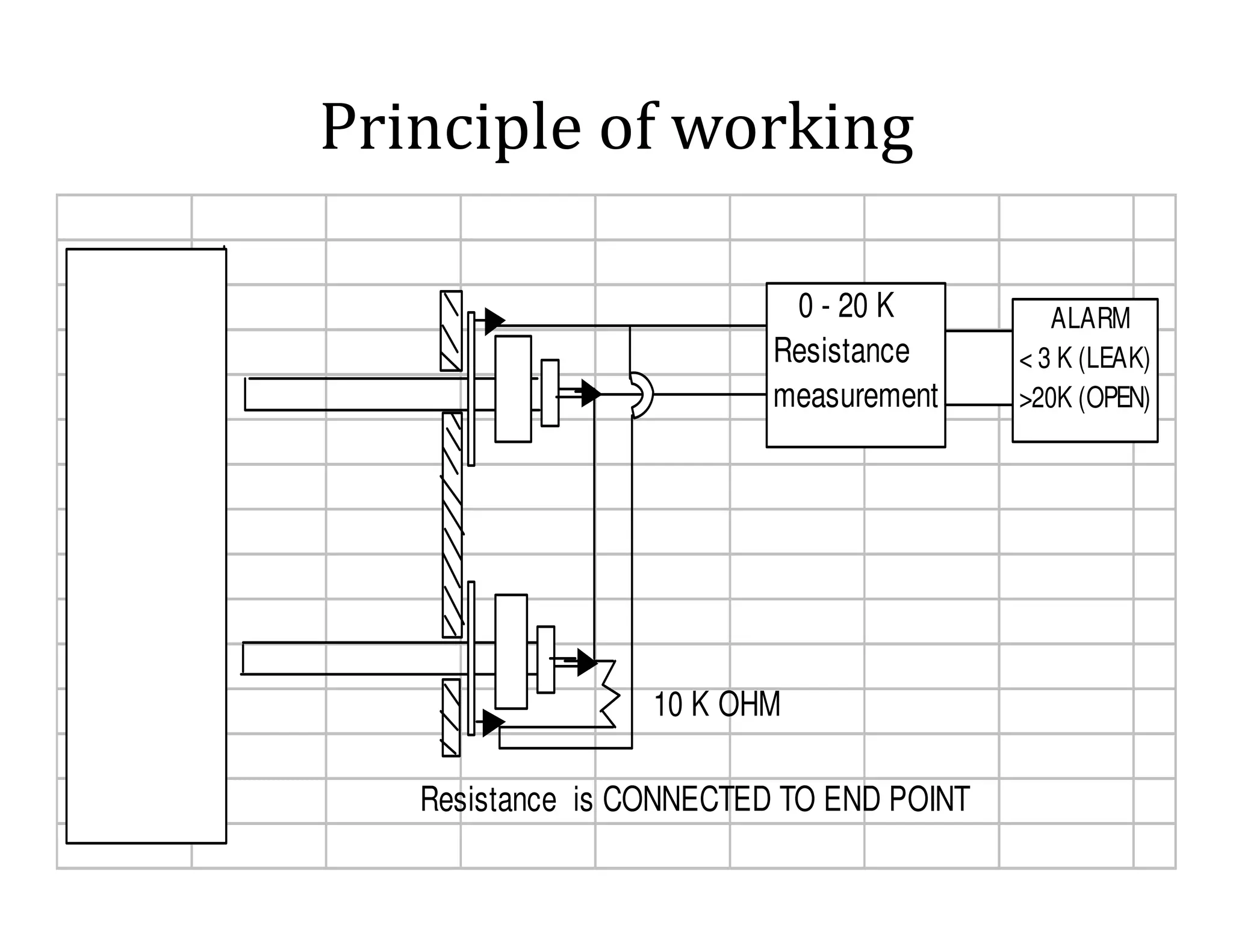
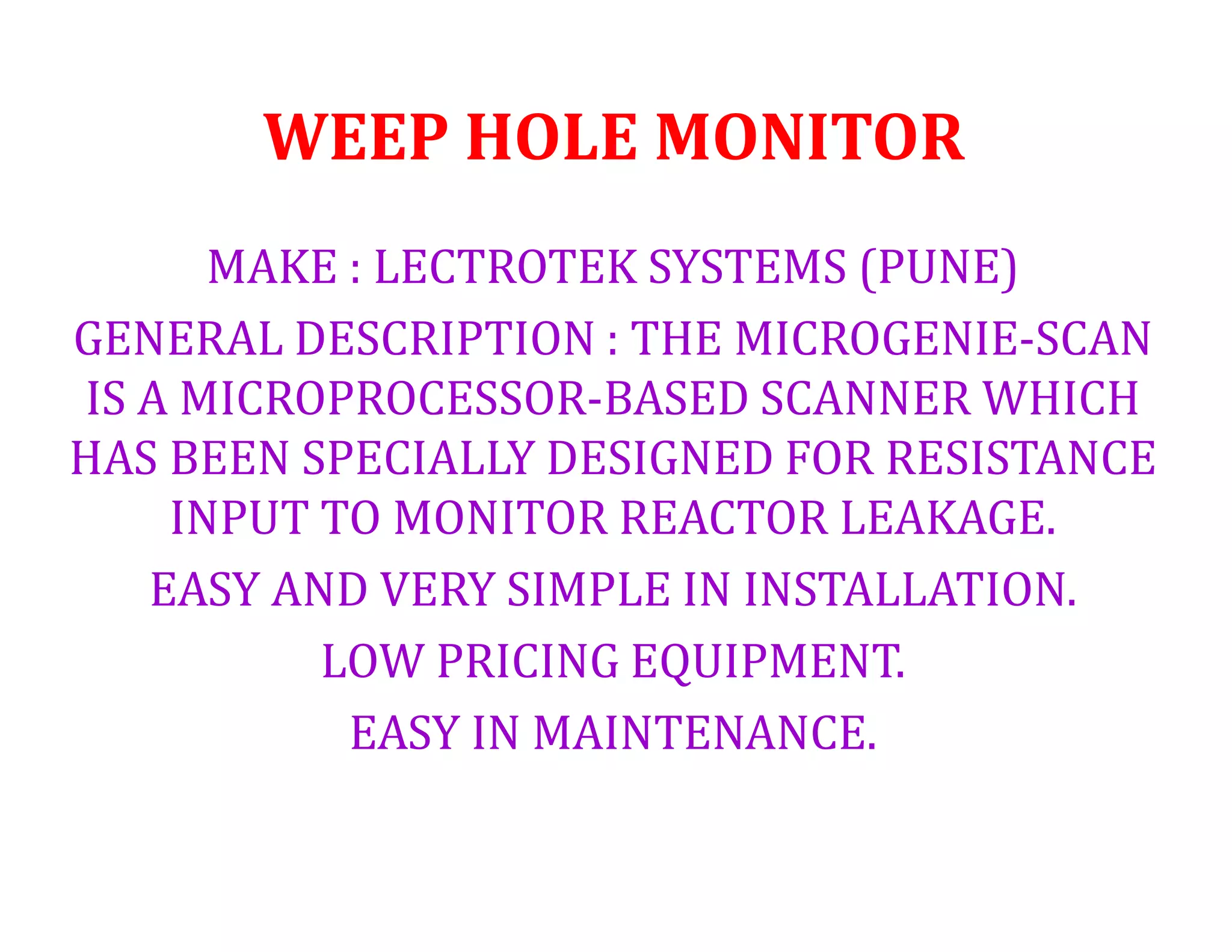
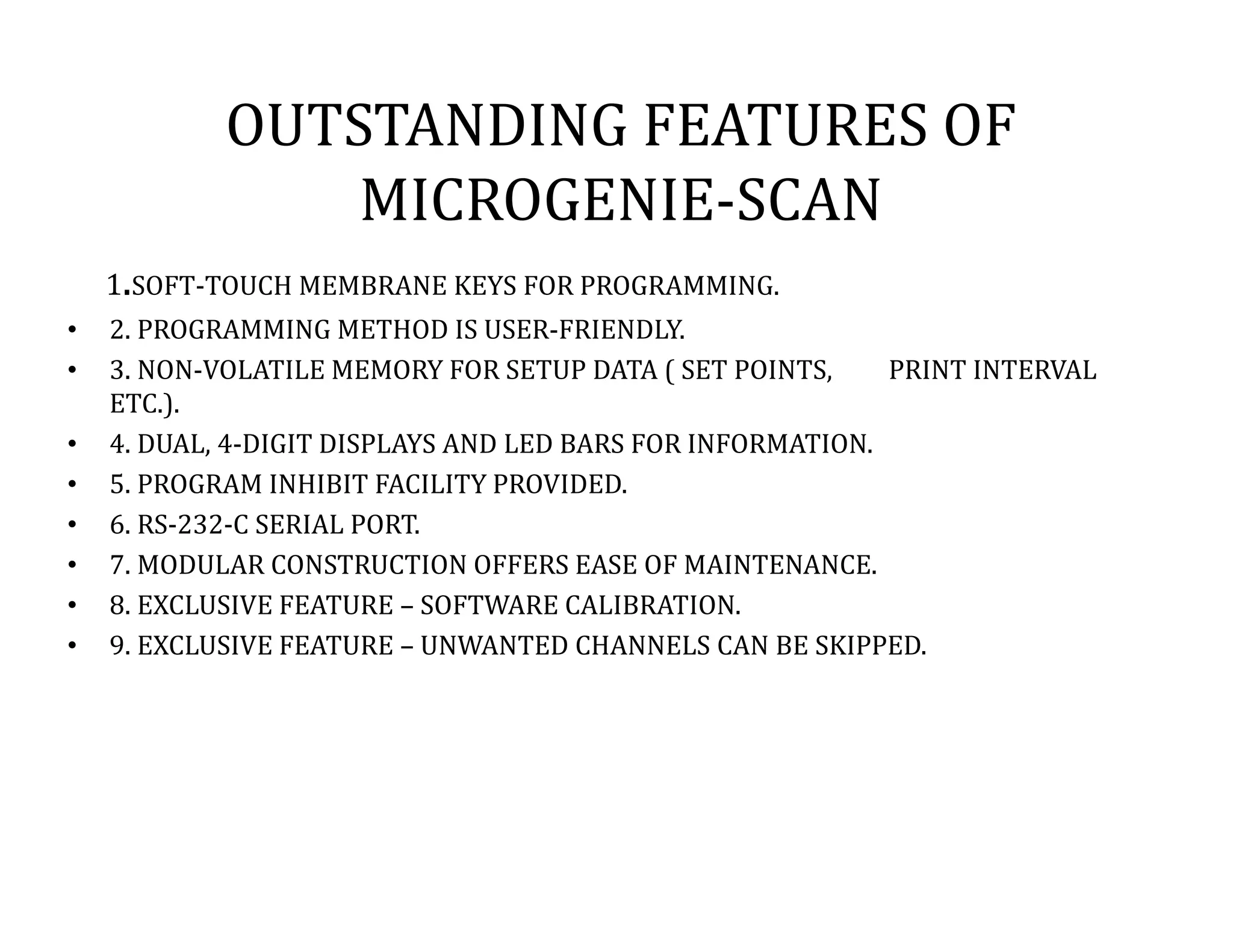
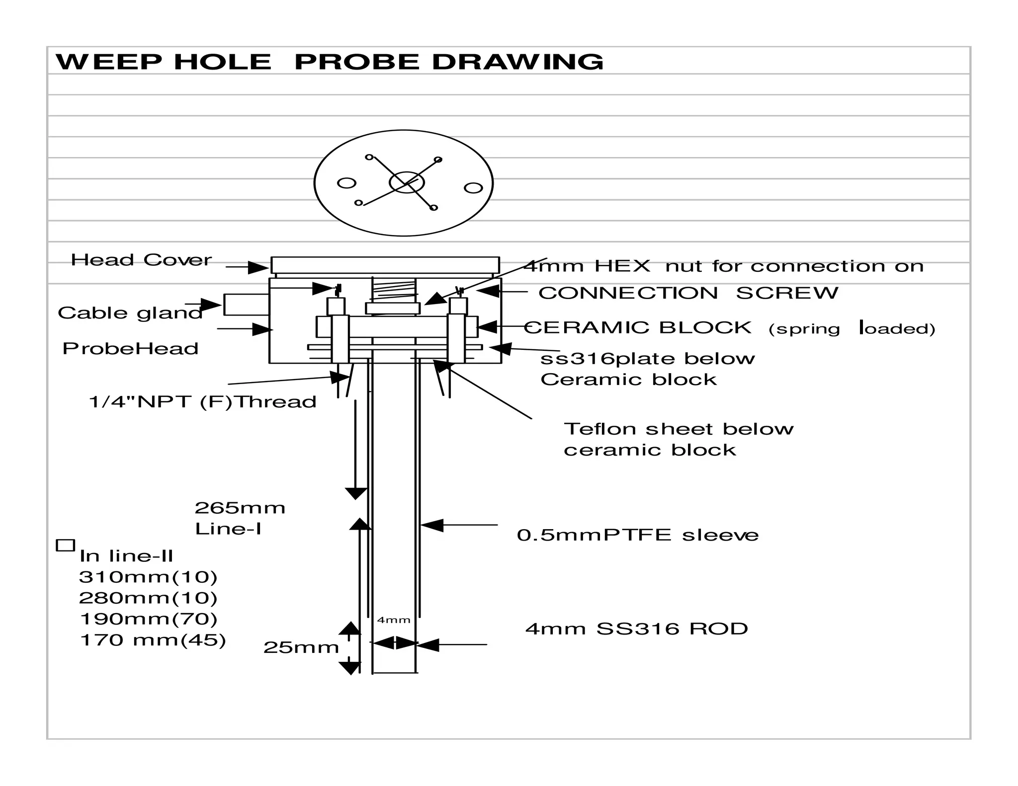
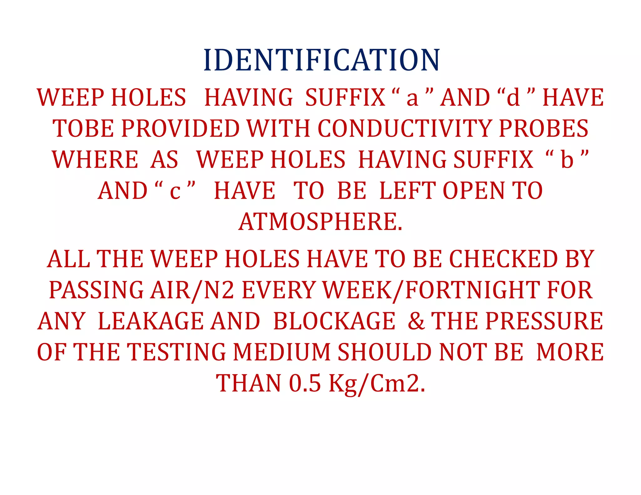
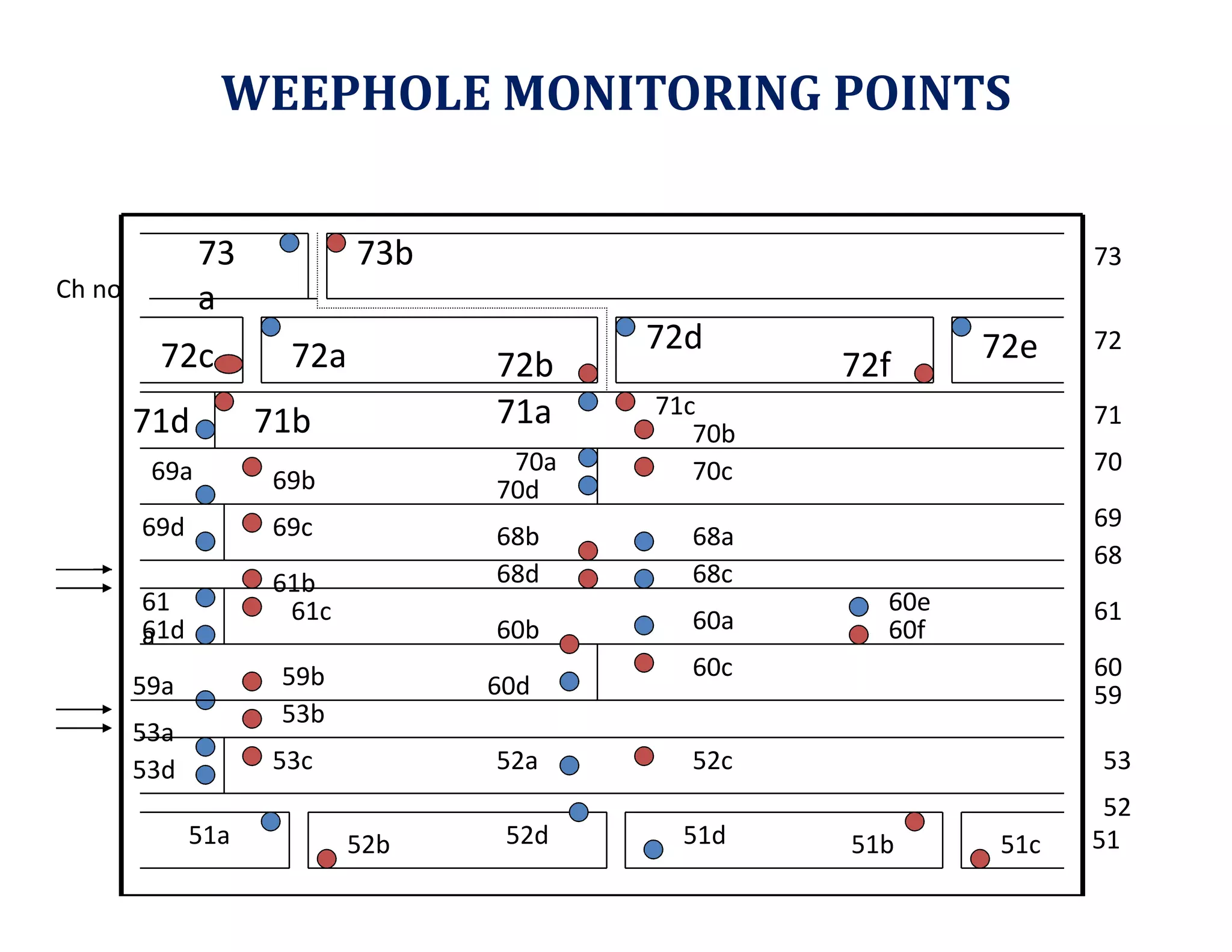
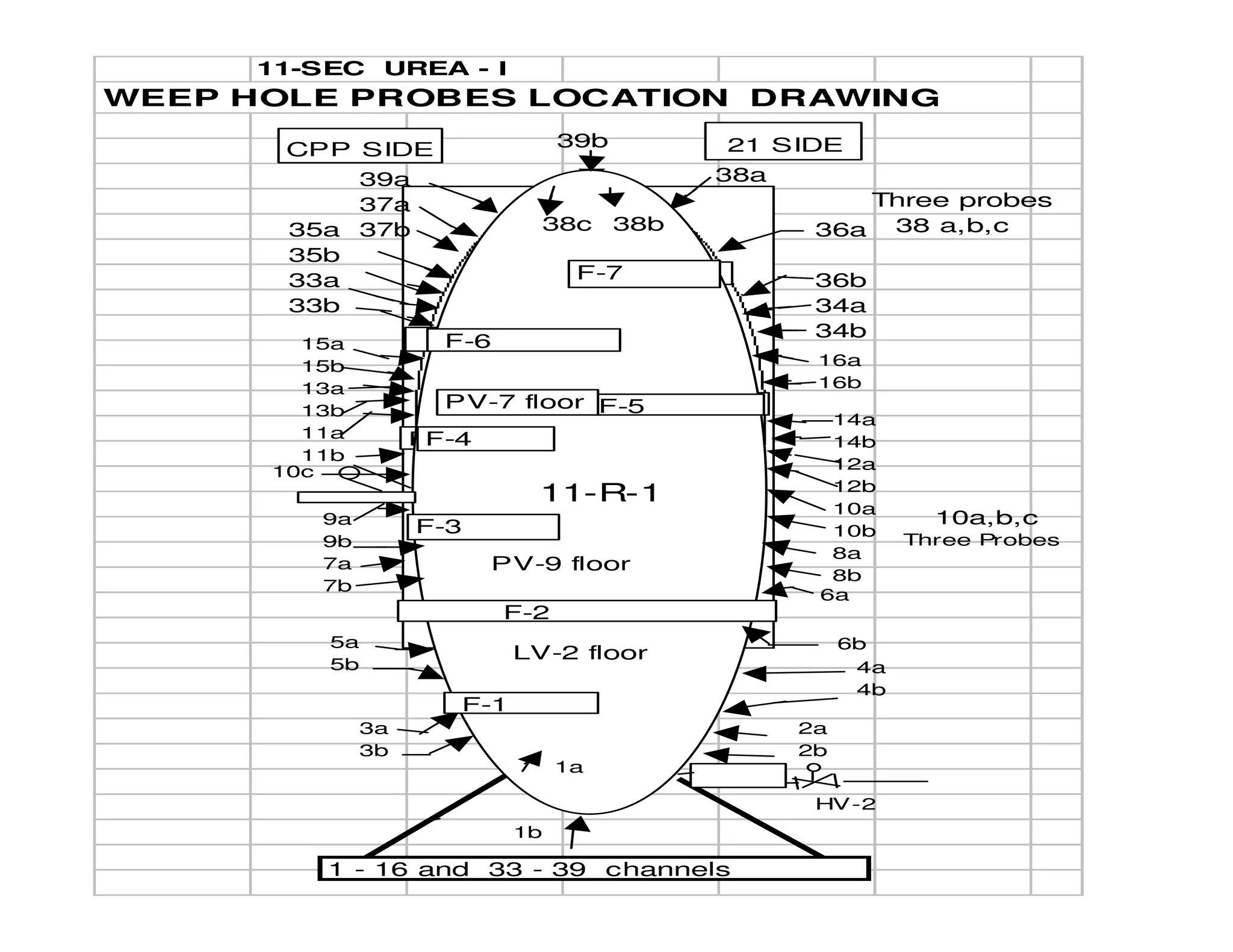
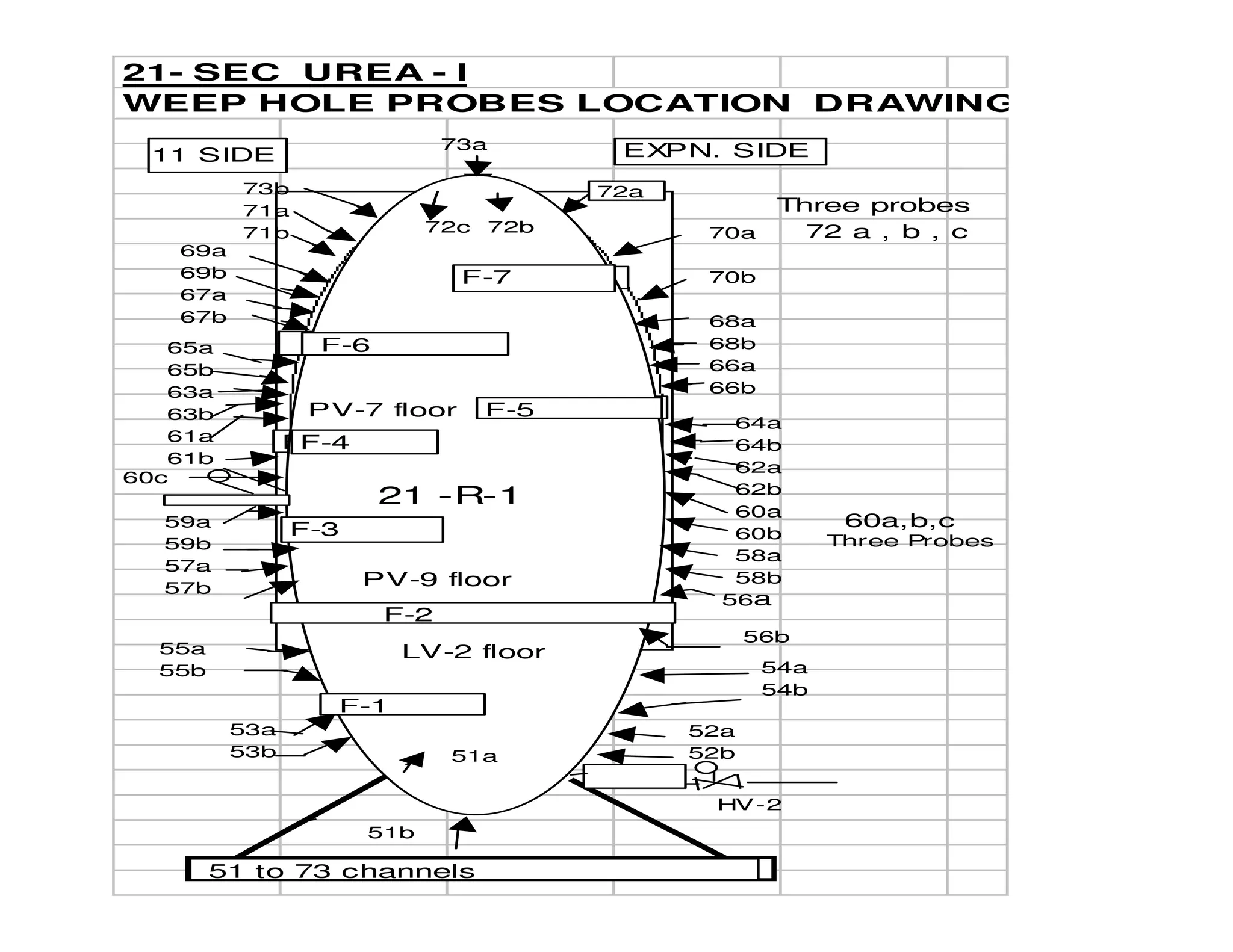
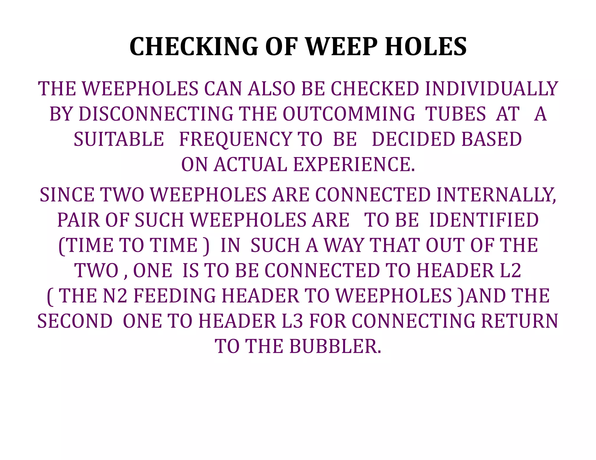
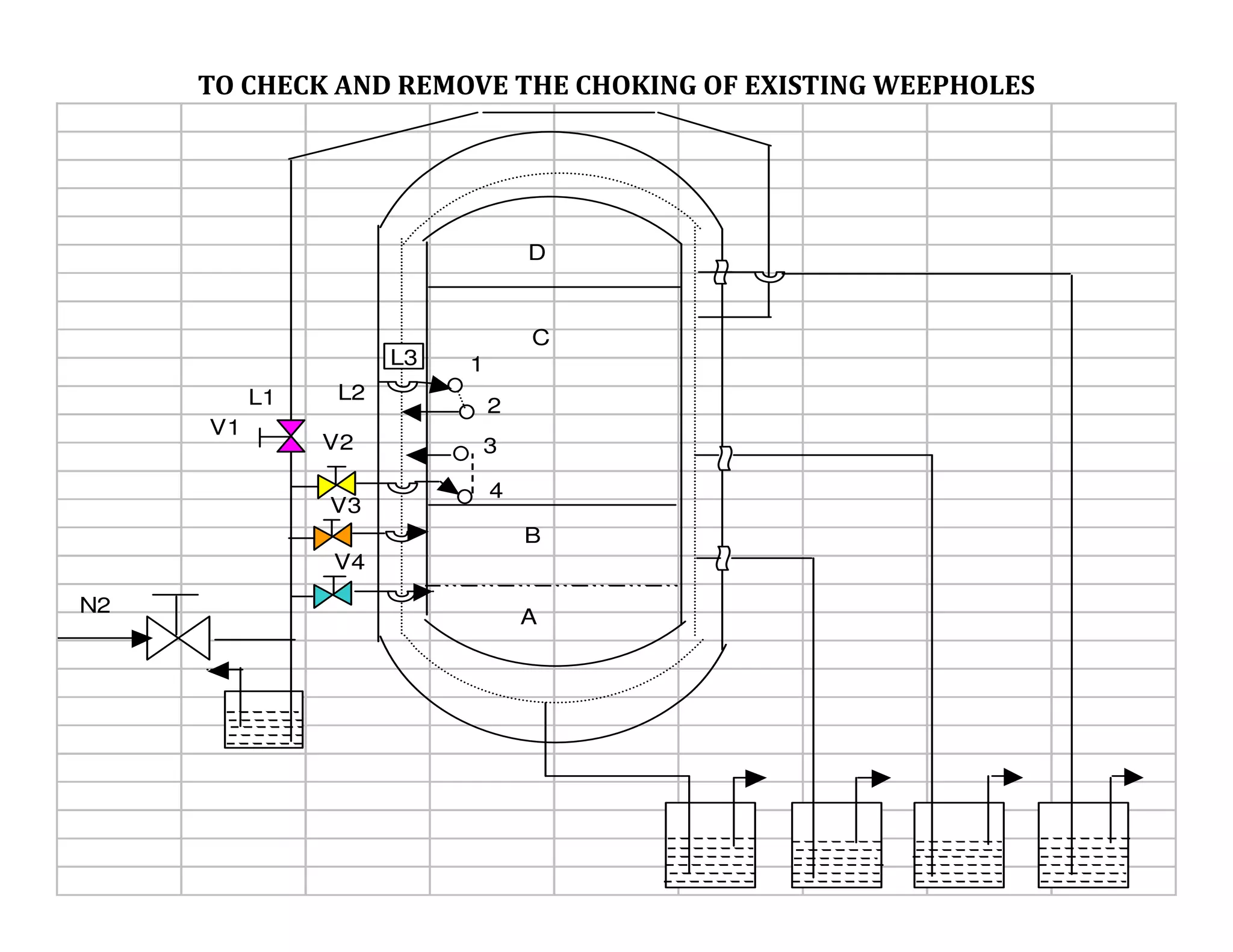


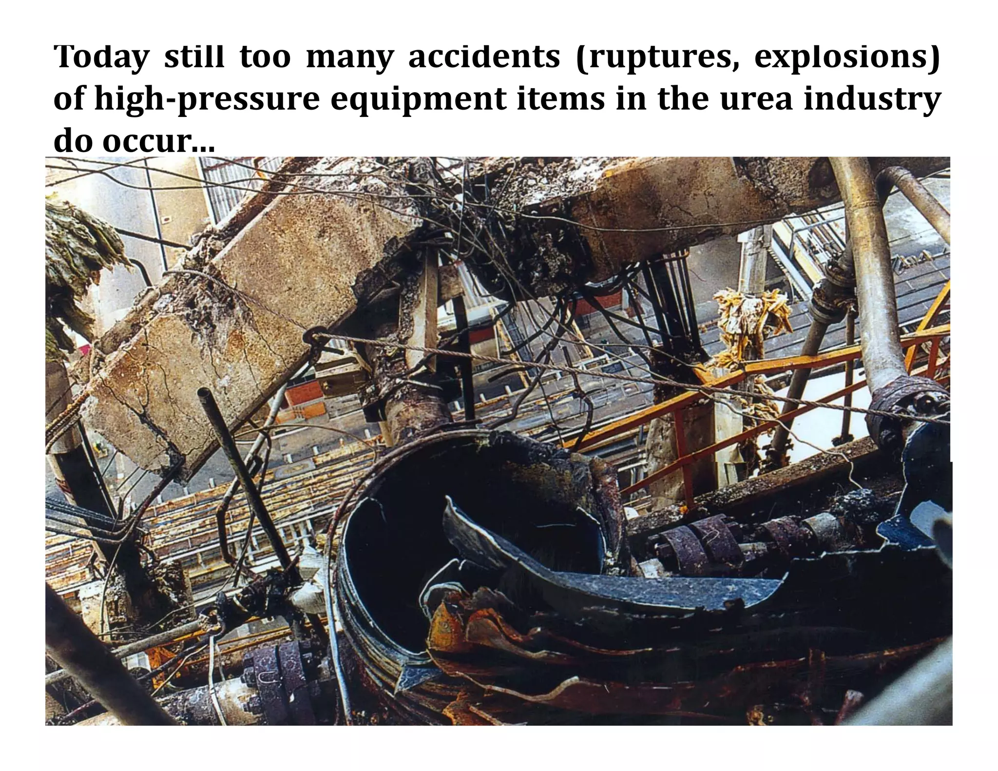


The document discusses a weep hole monitoring system installed in a urea plant reactor and stripper vessels to detect any leakage from the vessels. The system works by connecting each weep hole internally through grooves to another weep hole, with nitrogen passed through one hole of each pair and the other hole connected to bubblers for continuous monitoring to ensure nitrogen flow through all pairs. The Microgenie-Scan scanner monitors the resistance of each weep hole pair to detect leaks below 3k ohms and openings above 20k ohms. Safety risks of high pressure equipment in urea plants are also discussed.