This document provides guidelines for hydraulic calculations and line sizing for process plants. It outlines the general approach to hydraulic calculations, including pressure drop criteria, equivalent lengths of valves and fittings, and flow regimes for vapor-liquid mixed phase flow. Tables with typical line sizing criteria are included for liquid, vapor, gas and two-phase flow lines. Special considerations and calculation methods are described for thermosyphon reboiler circuits, kettle reboiler circuits, pump NPSH, and vacuum tower transfer lines. Appendices provide references and additional tables and figures to support the guidelines.
![DG-PPG-0110
Document No.
MUSTANG
Process Plants Process Design Guidelines:
Hydraulics and Line Sizing Rev. 0
1.0 SCOPE
This section outlines the general guidelines for hydraulic calculation of piping systems. It is
intended to provide a consistent approach to hydraulic calculations as performed by Process
Engineers / Technical Professionals, but not to cover every special case one may encounter.
Guidelines for calculating pressure drop through equipment such as trays, packings and
reactors are included in other guidelines.
2.0 HYDRAULICS CALCULATION
Mustang has several line sizing programs available in myMustang®. Refer to the Sizing page
within the Process portal. Regardless of the program or method selected, there are
independent variables to consider.
2.1 Pressure Drop Criteria
Absolute Roughness Factor: use 0.00015 ft for commercial steel pipe. For non-steel
pipe, use factors given in the Fluid Flow section of the GPSA Engineering Data Book [2].
Pipe Age Factor: use 1.2 unless noted otherwise in the design basis for a specific
project.
For vapor-liquid mixed phase, the Hughmark "in-place” density may be used, where
available as an option, for calculating static head.
2.2 Equivalent Length of Valves and Fitting
Use the table shown as Figure 17-4 in the GPSA Engineering Data Book [2].
Spreadsheet templates which use average L/D ratios and yield essentially the same
equivalent lengths may also be used. Optionally, Crane No. 410 [1] provides equations
for calculating valve and fitting losses as velocity head equivalents.
2.3 Flow Regimes of Vapor-Liquid Mixed Phase Flow
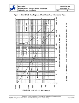
• Horizontal flow: Use Baker chart shown in Figure 1.
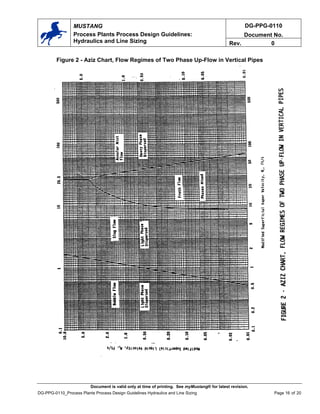
• Vertical flow: Use the Aziz Chart, Figure 2, via Reference 2. This figure is
considered to be conservative and valid for pressure up to 150 psig, which covers
the range of concern.
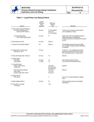
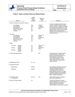
3.0 LINE SIZING CRITERIA
Tables 1, 2, and 3 in Appendix B give some typical "rules of thumb" for line sizing. Although
these rules are applicable to most situations, they may not be suitable in all cases. For critical
circuits, hydraulics should be checked in detail to confirm the available pressure drop regardless
of whether the lines meet rules-of-thumb criteria. In addition, the optimum line size is
determined by balancing the capital cost of the piping system against the operating cost of
pumps and/or compressors. To minimize initial investment, special attention should be given to
expensive lines, for example:
Document is valid only at time of printing. See myMustang® for latest revision.
DG-PPG-0110_Process Plants Process Design Guidelines Hydraulics and Line Sizing Page 3 of 20](https://image.slidesharecdn.com/linesizing-mustang-220523084545-e8a2ec76/85/line-sizing-mustang-pdf-3-320.jpg)
![DG-PPG-0110
Document No.
MUSTANG
Process Plants Process Design Guidelines:
Hydraulics and Line Sizing Rev. 0
• Use the percent vaporization specified in the reboiler data sheet. Recirculating
thermosyphon reboilers are generally designed for 30 wt% vaporization.
Once-through thermosyphon reboilers can have up to 50 wt% vaporization.
• Process Engineer / Technical Professional should check the actual operating
pressure of the reboiler if the mean temperature difference between the heating
medium and circulation fluid is sensitive to pressure variation. The pressure of the
boiling medium in the thermosyphon reboiler is equal to the tower operating pressure
plus riser losses including static head based on in-place density.
• The reboiler return line should be sized to avoid slugging problems. However, this
may not always be possible without an excessive elevation of skirt height, especially
for light ends towers operated at high pressure. It is generally recognized that towers
operated above a certain operating pressure (subject to engineering judgment), slug
flow may not exist or is not detrimental to a reboiler/tower operation.
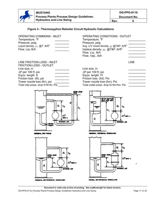
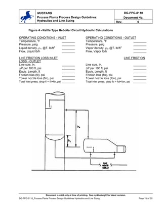
5.2 Kettle Reboiler Circuits
The worksheet shown on Figure 4 should be used for hydraulic calculations associated
with kettle reboiler circuits. Design considerations for the kettle reboiler system are as
follows:
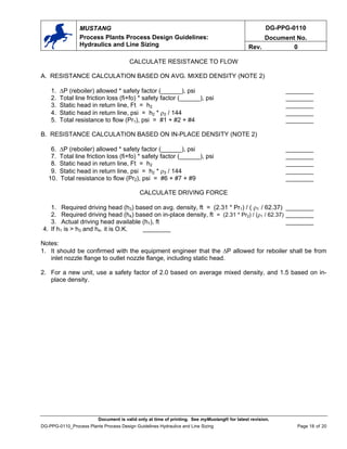
• Use a safety factor of 1.5 for line friction loss and allowable total reboiler pressure
drop.
• If the product from the kettle reboiler flows to a pump suction, the elevation of kettle
should also satisfy pump NPSH requirement.
• If the product from the kettle reboiler flows to a heat exchanger first, free drain from
the kettle to exchanger is preferred. This is not a mandatory requirement if the
product is of multi-component mixtures with wide boiling ranges. However, the pipe
length and elevation rise shall be minimized.
5.3 Pump NPSH and Pump Hydraulics Calculations
Refer to “Pumps" [3] for calculation guidelines and procedures.
5.4 Vacuum Tower Transfer Line Sizing
Transfer lines in crude vacuum units are typically very large and are constructed of
expensive alloy material. It is imperative that the process designer perform a detailed
hydraulic calculation to select the smallest line size.
The maximum velocity should be limited to 90% of sonic velocity. It usually occurs at the
inlet nozzle to the vacuum tower. Sonic velocity is expressed as:
VS = 68.1(kP/ρ)1/2
VS sonic velocity, ft/s
k the specific heat ratio, Cp/Cv
P the absolute pressure, psia
ρ the homogeneous mixed phase density, lb/ft3
The total pressure drop from the heater outlet to the tower inlet is limited by the heater
outlet temperature, which is typically 25°F higher than the flash zone temperature and
Document is valid only at time of printing. See myMustang® for latest revision.
DG-PPG-0110_Process Plants Process Design Guidelines Hydraulics and Line Sizing Page 6 of 20](https://image.slidesharecdn.com/linesizing-mustang-220523084545-e8a2ec76/85/line-sizing-mustang-pdf-6-320.jpg)
![DG-PPG-0110
Document No.
MUSTANG
Process Plants Process Design Guidelines:
Hydraulics and Line Sizing Rev. 0
APPENDICES
Appendix A: References
[1] “Flow of Fluids through Valves, Fittings, and Pipe,” Crane Technical Paper No. 410,
1988.
[2] “Fluid Flow and Piping,” GPSA Engineering Data Book, 10th ed., 1987, Section 17,
Volume II.
[3] “Process Plants Process Design Guidelines: Pumps”, Mustang Department Guidelines,
DG-PPG-0107.
[4] KYPIPE User's Manual.
[5] "Centrifugal Compressor Inlet Piping - A Practical Guide," Elliott Compressor, Reprint No.
117.
Document is valid only at time of printing. See myMustang® for latest revision.
DG-PPG-0110_Process Plants Process Design Guidelines Hydraulics and Line Sizing Page 8 of 20](https://image.slidesharecdn.com/linesizing-mustang-220523084545-e8a2ec76/85/line-sizing-mustang-pdf-8-320.jpg)