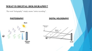
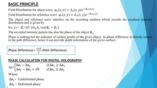
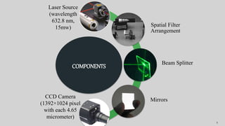
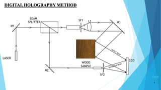
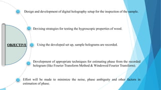
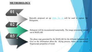
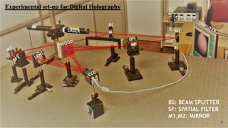
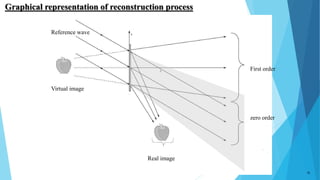
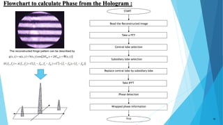
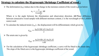
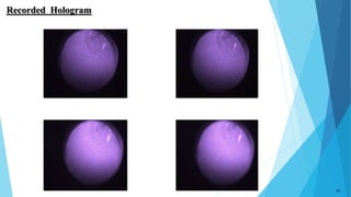
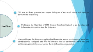
Characterization of hygroscopic
properties of wood using
digital holography
Puneet Singh Thakur
M.E. (Digital Instrumentation)
Roll No. 15DI3109
1
2
CONTENTS
 Introduction
 Basic principle
 Components
 Experimental setup & digital recording of hologram
 Reconstruction process(using image processing )
 Problem domain
 Objectives
 Methodology
 Strategy & description
 References
WHAT IS DIGITAL HOLOGRAPHY?
The word “holography” simply means “entire recording”.
3
PHOTOGRAPHY DIGITAL HOLOGRAPHY
CCD
BASIC PRINCIPLE
Field Distribution for object wave 𝜑 𝑜 𝑥, 𝑦 = 𝐴 𝑜(𝑥, 𝑦)𝑒−𝑖𝜃 𝑜(𝑥,𝑦)
Field Distribution for reference wave 𝜑 𝑟 𝑥, 𝑦 = 𝐴 𝑟(𝑥, 𝑦)𝑒−𝑖𝜃 𝑟(𝑥,𝑦)
The object and reference wave interfere on the recording medium which records the resultant intensity
distribution and is given by
I(x, y) = 𝐴 𝑜
2+𝐴 𝑟
2+2𝐴 𝑜 𝐴 𝑟 cos(∅ 𝑜 − ∅ 𝑟)
The recorded intensity pattern has also the phase of the object ∅ 𝑜.
Phase is nothing but the indicator of surface profile of the given object. As phase difference is directly related
to the path difference, hence it can provide depth information of the given surface.
Phase Difference=
2×Π
𝜆
(Path Difference)
PHASE CALCULATION FOR DIGITAL HOLOGRAPHY
Δø=
Δø1 − Δø2 𝑖𝑓Δø1 ≥ Δø2
Δø2 − Δø1 + 2Π 𝑖𝑓Δø1 ≤ Δø2
Where
Δø1= Undeformed phase
Δø2 = Deformed phase
4
COMPONENTS
Spatial Filter
Arrangement
Beam Splitter
Mirrors
Laser Source
(wavelength
632.8 nm,
15mw)
CCD Camera
(1392×1024 pixel
with each 4.65
micrometer)
5
DIGITAL HOLOGRAPHY METHOD
6
BEAM
SPLITTER
SF1 L1 M3
CCD
SF2
LASER
M1
M2
WOOD
SAMPLE
Back
>
>
>
>
>
>
>
Wood has some unusual characteristic that must be understood and considered for its
optimal utilization.
The dimensional changes i.e., the shrinkage and swelling of wood, are
responsible for the major source of structural problem in parts made of wood.
This coefficient is a measure of the shrinkage caused by a unit decrease in the moisture
content of the wood sample.
PROBLEM
DOMAIN
Here we try to figure out the Hygroscopic Shrinkage Coefficient.
The dimensional changes (shrinkage and swelling) of wood are related to the
moisture content in the environment and the temperature. But there are more
changes when there are changes in the moisture content in the environment
rather than changes in temperature.
 Wood shrinks when it dries, and the shrinkage is uneven over the cross section due to the different shrinkage
properties in the radial, tangential and longitudinal directions.
 Radial shrinkage is the amount the wood moves perpendicular to the growth rings.
 Tangential shrinkage the amount the wood moves along the growth rings.
 Longitudinal shrinkage is the lengthwise change in the wood.
Longitudinal shrinkage is very small as compare to the tangential and radial shrinkage.
8
RADIAL
SHRINKAGE
TANGENTIAL
SHRINKAGE
GROWTH
RINGS
Devising strategies for testing the hygroscopic properties of wood.
Using the developed set up, sample holograms are recorded.
Development of appropriate techniques for estimating phase from the recorded
hologram (like Fourier Transform Method & Windowed Fourier Transform).
Effort will be made to minimize the noise, phase ambiguity and other factors in
estimation of phase.
Design and development of digital holography setup for the inspection of the sample.
OBJECTIVE
Basically proposed set up (Slide No. 6) will be used to capture the
Holograms.
Hologram will be reconstructed numerically. The image processing carried
out in MATLAB.
The phase map generated by the MATLAB for the different hologram will
Give us the information about the drying process, hence we can extract
Hygroscopic properties of wood.
.
01
02
03
METHODOLOGY
10
BS
M1
BS: BEAM SPLITTER
SF: SPATIAL FILTER
M1,M2: MIRROR
Experimental set-up for Digital Holography
11
12
Graphical representation of reconstruction process
Reference wave
Real image
Virtual image
First order
zero order
13
Diffraction field
calculation
Reference light
introduction
Obtain field in
object plane
Raw
Hologram
Reconstructed
Hologram
Phase
Calculation
Algorithm to reconstruction Process of Hologram
(Requires Digital Image Processing)
14
Reconstruction Process of Hologram
(Requires Digital Image Processing)
The complete simulation can be separated into three steps.
Step 1: Diffraction field calculation (Fresnel diffraction).
Step 2: Introduce a reference light to the CCD plane and calculate the resulting interference fringes. This
step together with step 1 is to simulate holographic recording.
Step 3: Find the field in the object plane from the field producing from the hologram (backward propagation).
This step is to simulate holographic reconstruction.
START
Read the Reconstructed image
Take a FFT
Central lobe selection
Subsidiary lobe selection
Replace central lobe by subsidiary lobe
Take IFFT
Phase detection
Wrapped phase information
Stop
Flowchart to calculate Phase from the Hologram :
15
The reconstructed fringe pattern can be described by
𝑢 𝑥 =
𝜆
4 cos(
𝛼
2
)
∆∅
𝜀 𝑥𝑥 =
𝑢 𝑥 𝑥+Δ𝑥 ,𝑦 −𝑢 𝑥(𝑥, 𝑦)
𝑥
𝜀 𝑥𝑥 =
𝑢 𝑥 𝑥+Δ𝑥 ,𝑦 −𝑢 𝑥(𝑥, 𝑦)
𝑥.Δ𝑡
 The deformation (𝑢 𝑥) induce due to the change in the moisture content of the wood is given below:
Where 𝛼 is the angle between the illumination and observation direction, ∆∅ Phase difference
between consecutive wood sample with different moisture content, 𝜆 is the wavelength of the LASER
source used.
 To calculate the induced strain (𝜀 𝑥𝑥) , the displacement will be differentiated, which given by:
 The strain rate is given by
Strategy to calculate the Hygroscopic Shrinkage Coefficient of wood :
16
 For the calculation of the hygroscopic shrinkage coefficient, a curve will be fitted to the strain data.
The slope of the fitted curve is the hygroscopic shrinkage coefficient of the wood.
Recorded Hologram
17
Working on the Algorithm of FTM (Fourier Transform Method) to get the phase and
deformation information from the Hologram.
Also working on the phase unwrapping algorithm so that we can get the unwrap phase map
of the recorded Hologram. That will we correlated with the deformation, which will give
us the strain generated in wood sample due to different moisture content.
Till now we have generated the sample Hologram of the wood sample and trying to
reconstruct it numerically.
Next Steps
18
19
1. U. Schnars, T. K. Kreis, and W. Juptner,“Digital recording and numerical reconstruction of holograms,” Optical
Engineering 35, 977-82 (1996).
2. S. Grilli, P. Ferraro, R. Meucci, S. De Nicola, A. Finizio and G. Pierattini, “Whole optical wave fields reconstruction
by Digital Holography,” Optics Express 9, 294-302 (2001).
3. Gombkoto, J. Kornis, Z. Fuzessy “Difference displacement measurement using digital holography,” Optics
Communications 214, 115-121 (2002).
4. N. K. Nishchal, J. Joseph, and K. Singh, “Fully phase encryption using digital holography,” Optical Engineering 43,
2959-2966 (2004).
5. M. Hossain, G. Sheoran, D. S. Mehta, and C. Shakher, “Contouring of diffused objects by using digital holography,”
Optics and Lasers in Engineering 45, 684–689 (2007).
6. Hossain, G. Sheoran, D. S. Mehta, and C. Shakher, “Contouring of diffused objects by using digital holography,”
Optics and Lasers in Engineering 45, 684–689 (2007).
7. M. K. Kim, “Principles and techniques of digital holographic microscopy,” SPIE Reviews 1, 018005-1- 50 (2010).
8. P. Tankam, and P. Picart, “Use of digital holography for crack investigation in electronic components,” Optics and
Lasers in Engineering 49, 1335–1342 (2011).
9. P. P. Banerjee, “Recent Trends in Digital Holography,” 12th International Conference on Fiber Optics and Photonics,
(2014).
10. V. Kumar and C. Shakher ,“Study of heat dissipation process from heat sink using lens less Fourier transform digital
holographic interferometry,” Applied Optics 54, 1257-65 (2015).
REFERENCES
20
THANK YOU

Holography

  • 1.
    Characterization of hygroscopic propertiesof wood using digital holography Puneet Singh Thakur M.E. (Digital Instrumentation) Roll No. 15DI3109 1
  • 2.
    2 CONTENTS  Introduction  Basicprinciple  Components  Experimental setup & digital recording of hologram  Reconstruction process(using image processing )  Problem domain  Objectives  Methodology  Strategy & description  References
  • 3.
    WHAT IS DIGITALHOLOGRAPHY? The word “holography” simply means “entire recording”. 3 PHOTOGRAPHY DIGITAL HOLOGRAPHY CCD
  • 4.
    BASIC PRINCIPLE Field Distributionfor object wave 𝜑 𝑜 𝑥, 𝑦 = 𝐴 𝑜(𝑥, 𝑦)𝑒−𝑖𝜃 𝑜(𝑥,𝑦) Field Distribution for reference wave 𝜑 𝑟 𝑥, 𝑦 = 𝐴 𝑟(𝑥, 𝑦)𝑒−𝑖𝜃 𝑟(𝑥,𝑦) The object and reference wave interfere on the recording medium which records the resultant intensity distribution and is given by I(x, y) = 𝐴 𝑜 2+𝐴 𝑟 2+2𝐴 𝑜 𝐴 𝑟 cos(∅ 𝑜 − ∅ 𝑟) The recorded intensity pattern has also the phase of the object ∅ 𝑜. Phase is nothing but the indicator of surface profile of the given object. As phase difference is directly related to the path difference, hence it can provide depth information of the given surface. Phase Difference= 2×Π 𝜆 (Path Difference) PHASE CALCULATION FOR DIGITAL HOLOGRAPHY Δø= Δø1 − Δø2 𝑖𝑓Δø1 ≥ Δø2 Δø2 − Δø1 + 2Π 𝑖𝑓Δø1 ≤ Δø2 Where Δø1= Undeformed phase Δø2 = Deformed phase 4
  • 5.
    COMPONENTS Spatial Filter Arrangement Beam Splitter Mirrors LaserSource (wavelength 632.8 nm, 15mw) CCD Camera (1392×1024 pixel with each 4.65 micrometer) 5
  • 6.
    DIGITAL HOLOGRAPHY METHOD 6 BEAM SPLITTER SF1L1 M3 CCD SF2 LASER M1 M2 WOOD SAMPLE Back > > > > > > >
  • 7.
    Wood has someunusual characteristic that must be understood and considered for its optimal utilization. The dimensional changes i.e., the shrinkage and swelling of wood, are responsible for the major source of structural problem in parts made of wood. This coefficient is a measure of the shrinkage caused by a unit decrease in the moisture content of the wood sample. PROBLEM DOMAIN Here we try to figure out the Hygroscopic Shrinkage Coefficient. The dimensional changes (shrinkage and swelling) of wood are related to the moisture content in the environment and the temperature. But there are more changes when there are changes in the moisture content in the environment rather than changes in temperature.
  • 8.
     Wood shrinkswhen it dries, and the shrinkage is uneven over the cross section due to the different shrinkage properties in the radial, tangential and longitudinal directions.  Radial shrinkage is the amount the wood moves perpendicular to the growth rings.  Tangential shrinkage the amount the wood moves along the growth rings.  Longitudinal shrinkage is the lengthwise change in the wood. Longitudinal shrinkage is very small as compare to the tangential and radial shrinkage. 8 RADIAL SHRINKAGE TANGENTIAL SHRINKAGE GROWTH RINGS
  • 9.
    Devising strategies fortesting the hygroscopic properties of wood. Using the developed set up, sample holograms are recorded. Development of appropriate techniques for estimating phase from the recorded hologram (like Fourier Transform Method & Windowed Fourier Transform). Effort will be made to minimize the noise, phase ambiguity and other factors in estimation of phase. Design and development of digital holography setup for the inspection of the sample. OBJECTIVE
  • 10.
    Basically proposed setup (Slide No. 6) will be used to capture the Holograms. Hologram will be reconstructed numerically. The image processing carried out in MATLAB. The phase map generated by the MATLAB for the different hologram will Give us the information about the drying process, hence we can extract Hygroscopic properties of wood. . 01 02 03 METHODOLOGY 10
  • 11.
    BS M1 BS: BEAM SPLITTER SF:SPATIAL FILTER M1,M2: MIRROR Experimental set-up for Digital Holography 11
  • 12.
    12 Graphical representation ofreconstruction process Reference wave Real image Virtual image First order zero order
  • 13.
    13 Diffraction field calculation Reference light introduction Obtainfield in object plane Raw Hologram Reconstructed Hologram Phase Calculation Algorithm to reconstruction Process of Hologram (Requires Digital Image Processing)
  • 14.
    14 Reconstruction Process ofHologram (Requires Digital Image Processing) The complete simulation can be separated into three steps. Step 1: Diffraction field calculation (Fresnel diffraction). Step 2: Introduce a reference light to the CCD plane and calculate the resulting interference fringes. This step together with step 1 is to simulate holographic recording. Step 3: Find the field in the object plane from the field producing from the hologram (backward propagation). This step is to simulate holographic reconstruction.
  • 15.
    START Read the Reconstructedimage Take a FFT Central lobe selection Subsidiary lobe selection Replace central lobe by subsidiary lobe Take IFFT Phase detection Wrapped phase information Stop Flowchart to calculate Phase from the Hologram : 15 The reconstructed fringe pattern can be described by
  • 16.
    𝑢 𝑥 = 𝜆 4cos( 𝛼 2 ) ∆∅ 𝜀 𝑥𝑥 = 𝑢 𝑥 𝑥+Δ𝑥 ,𝑦 −𝑢 𝑥(𝑥, 𝑦) 𝑥 𝜀 𝑥𝑥 = 𝑢 𝑥 𝑥+Δ𝑥 ,𝑦 −𝑢 𝑥(𝑥, 𝑦) 𝑥.Δ𝑡  The deformation (𝑢 𝑥) induce due to the change in the moisture content of the wood is given below: Where 𝛼 is the angle between the illumination and observation direction, ∆∅ Phase difference between consecutive wood sample with different moisture content, 𝜆 is the wavelength of the LASER source used.  To calculate the induced strain (𝜀 𝑥𝑥) , the displacement will be differentiated, which given by:  The strain rate is given by Strategy to calculate the Hygroscopic Shrinkage Coefficient of wood : 16  For the calculation of the hygroscopic shrinkage coefficient, a curve will be fitted to the strain data. The slope of the fitted curve is the hygroscopic shrinkage coefficient of the wood.
  • 17.
  • 18.
    Working on theAlgorithm of FTM (Fourier Transform Method) to get the phase and deformation information from the Hologram. Also working on the phase unwrapping algorithm so that we can get the unwrap phase map of the recorded Hologram. That will we correlated with the deformation, which will give us the strain generated in wood sample due to different moisture content. Till now we have generated the sample Hologram of the wood sample and trying to reconstruct it numerically. Next Steps 18
  • 19.
    19 1. U. Schnars,T. K. Kreis, and W. Juptner,“Digital recording and numerical reconstruction of holograms,” Optical Engineering 35, 977-82 (1996). 2. S. Grilli, P. Ferraro, R. Meucci, S. De Nicola, A. Finizio and G. Pierattini, “Whole optical wave fields reconstruction by Digital Holography,” Optics Express 9, 294-302 (2001). 3. Gombkoto, J. Kornis, Z. Fuzessy “Difference displacement measurement using digital holography,” Optics Communications 214, 115-121 (2002). 4. N. K. Nishchal, J. Joseph, and K. Singh, “Fully phase encryption using digital holography,” Optical Engineering 43, 2959-2966 (2004). 5. M. Hossain, G. Sheoran, D. S. Mehta, and C. Shakher, “Contouring of diffused objects by using digital holography,” Optics and Lasers in Engineering 45, 684–689 (2007). 6. Hossain, G. Sheoran, D. S. Mehta, and C. Shakher, “Contouring of diffused objects by using digital holography,” Optics and Lasers in Engineering 45, 684–689 (2007). 7. M. K. Kim, “Principles and techniques of digital holographic microscopy,” SPIE Reviews 1, 018005-1- 50 (2010). 8. P. Tankam, and P. Picart, “Use of digital holography for crack investigation in electronic components,” Optics and Lasers in Engineering 49, 1335–1342 (2011). 9. P. P. Banerjee, “Recent Trends in Digital Holography,” 12th International Conference on Fiber Optics and Photonics, (2014). 10. V. Kumar and C. Shakher ,“Study of heat dissipation process from heat sink using lens less Fourier transform digital holographic interferometry,” Applied Optics 54, 1257-65 (2015). REFERENCES
  • 20.