Download to read offline
![0
Multiple-Wavelength Holographic Interferometry
with Tunable Laser Diodes
Atsushi Wada
National Defense Academy
Japan
1. Introduction
Two-wavelength holographic interferometry is an effective technique to generate a contour
map of a diffusely reflecting surface (Friesem & Levy (1976); Heflinger & Wuerker (1969);
Hildebrand & Haines (1967); Yonemura (1985)). In this technique, two holograms are
recorded with two wavelengths. An interference fringe pattern is generated by superposing
two object images reconstructed from the holograms.
In digital holography, a hologram is recorded by an image sensor and saved into a computer.
An object image can be reconstructed by numerical calculation. Several reconstruction
methods were reported. Some of these have adjustablity of position and scale of a
reconstruction image (Yu & Kim (2006); Zhang et al. (2004)). An object phase distribution can
be obtained by the numerical reconstruction of digital holograms. Therefore, two-wavelength
digital holographic interferometry makes it possible to generate a contour map by numerical
extraction of a phase difference between two reconstructed images (Gass et al. (2003);
Parshall & Kim (2006); Wagner et al. (2000; 1999); Yamaguchi (2001); Yamaguchi et al. (2006)).
A phase difference extracted from reconstructed object images is wrapped into a half-open
interval (−π, π]. If a measured object height was large with respect to a synthetic wavelength,
2π ambiguities of the phase difference should be eliminated for retrieving the object profile.
Common phase unwrapping algorithms (Asundi & Wensen (1998); Servin et al. (1998)) which
use phase information of neighbor pixels can be applied when an object structure has no
discontinuity. However the algorithms can not work correctly for an object profile having
isolated region surrounded by discontinuous step.
An object profile with discontinuous structure can be measured by two-wavelength
interferometry with a sufficiently large synthetic wavelength. For example, two-wavelength
holographic interferometry with a ruby laser and a synthetic wavelength of ∼ 2 cm was
reported (Heflinger & Wuerker (1969); Pedrini et al. (1999)). Nevertheless the measurement
error tends to be amplified linearly with an increase in the synthetic wavelength since most
of the error sources are the product of the synthetic wavelength and an error of the extracted
phase difference (Cheng & Wyant (1984)).
A technique which eliminates 2π ambiguities by using a phase difference with a large
synthetic wavelength was reported (Cheng & Wyant (1985); de Groot (1991); Wagner et al.
(2000)). This technique makes it possible to measure a large step-height with high depth
resolution. Wagner et. al. reported multiple-wavelength holographic interferometry using
a dye laser. They combined three phase differences with synthetic wavelengths of 3.04 mm,
3
www.intechopen.com](https://image.slidesharecdn.com/intech-multiplewavelengthholographicinterferometrywithtunablelaserdiodes-170522204747/85/In-tech-multiple-wavelength_holographic_interferometry_with_tunable_laser_diodes-1-320.jpg)
![Multiple-Wavelength Holographic Interferometry with Tunable Laser Diodes 3
z
x’
point light source
reference wave
object wave
illumination light
h
θ
3D object
image sensor
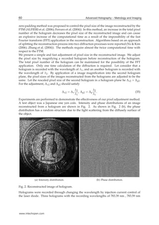
Fig. 1. Geometry of holographic interferometry.
and
U′
o( f ′
x, f ′
y) = F(u′
o) = dx′dy′u′
o(x′, y′) exp[−i2π( f ′
xx′ + f ′
yy′)]. (4)
Equation (2) can be written in terms of U′
o by substituting the spatial frequencies f ′
x = x/λz
and f ′
y = y/λz:
uo(x, y, z) =
1
z
exp iπ
x2 + y2
λz
U′
o
x
λz
,
y
λz
. (5)
An intensity distribution I(x, y, z) of an interference fringe pattern formed by the object wave
and the reference wave is given by
I(x, y, z) = |ur(x, y, z) + uo(x, y, z)|2
= |ur|2
+ |uo|2
+ u∗
r uo + uru∗
o
=
1
z2
1 + U′
o
x
λz
,
y
λz
2
+ U′
o
x
λz
,
y
λz
+ U′∗
o
x
λz
,
y
λz
=
1
z2
1 + U′
o( f ′
x, f ′
y)
2
+ U′
o( f ′
x, f ′
y) + U′∗
o ( f ′
x, f ′
y) .
(6)
In Eq. (6), the third term includes the Fourier spectrum of the object light. The object image
can be obtained by applying an inverse Fourier transform to I(x, y, z). The reconstructed wave
55Multiple-Wavelength Holographic Interferometry with Tunable Laser Diodes
www.intechopen.com](https://image.slidesharecdn.com/intech-multiplewavelengthholographicinterferometrywithtunablelaserdiodes-170522204747/85/In-tech-multiple-wavelength_holographic_interferometry_with_tunable_laser_diodes-3-320.jpg)
![4 Hologram / Book 2
field urec obtained by the transformation is given by
urec(x′
, y′
) =F−1
{I(x, y, z)}
=F−1
{I(λz f ′
x, λz f ′
y, z)}
= d f ′
xd f ′
y I(λz f ′
x, λz f ′
y, z) exp[i2π( f ′
xx′
+ f ′
yy′
)]
=λ2 δ(x′, y′)
λ2z2
+ u′
o(x′
, y′
) ⊗ u′∗
o (−x′
, −y′
) + u′
o(x′
, y′
) + u′∗
o (−x′
, −y′
) ,
(7)
where the symbol ⊗ stands for the convolution operator. In Eq. (7), the first term is the
reference point light source. The second term is an autocorrelation of the object light. The
third term expresses the object light produced by a spherical wave phase factor. The fourth
term is the complex conjugate of the third term. Since a phase factor does not affect intensity,
the intensity distribution of the object light can be reconstructed by the third term of Eq. (7).
Let consider that I(x, y, z) is recorded by an image sensor having Nx × Ny pixels with pixel
size of Δx × Δy. Numerical reconstruction of the digital hologram is realized through the
inverse discrete Fourier transform. Let the pixel size of the numerically reconstructed object
image be Δx
′ × Δy
′. The discrete formulation of Eq. (7) is then
urec(sΔx
′
, tΔy
′
) =
Nx/2−1
∑
p=−Nx/2
Ny/2−1
∑
q=−Ny/2
I(pΔx, qΔy, z) exp i2π
pΔx
λz
sΔ′
x +
qΔy
λz
tΔ′
y , (8)
where p, q are integers, and s, t are integers and fulfill x′ = sΔx
′, y′ = tΔy
′. The right side of
Eq. (8) is arranged in the form, in which fast Fourier transform can be applied:
urec(sΔx
′
, tΔy
′
) =
Nx/2−1
∑
p=−Nx/2
Ny/2−1
∑
q=−Ny/2
I(pΔx, qΔy, z) exp i2π
ps
Nx
+
qt
Ny
, (9)
where s, t, p and q are integers, and Δ′
x, Δ′
y satisfy the following condition
Δ′
x =
λz
Δx Nx
, Δ′
y =
λz
ΔyNy
, (10)
and
−Nx/2 ≤ s < Nx/2, −Ny/2 ≤ t < Ny/2. (11)
The field of view of the reconstructed image is λz/Δx × λz/Δy.
3. Multiple-wavelength interferometry
The reference plane is assumed to be placed at z = 0. Let the illumination light irradiate to
the object at an angle θ to the reference plane, and the height of the object surface respect to
the reference plane be h(x′, y′). The phase distribution φ(x′, y′) of the reconstructed image is
given by
φ(x′
, y′
) =
2π
λ
−L +
x′2 + y′2
2z
, (12)
56 Advanced Holography – Metrology and Imaging
www.intechopen.com](https://image.slidesharecdn.com/intech-multiplewavelengthholographicinterferometrywithtunablelaserdiodes-170522204747/85/In-tech-multiple-wavelength_holographic_interferometry_with_tunable_laser_diodes-4-320.jpg)
![Multiple-Wavelength Holographic Interferometry with Tunable Laser Diodes 5
where L is an optical path difference caused by the object surface structure, giving
L = (1 + cos θ)h(x′, y′) − x′ sin θ. (13)
The second term of Eq. (12) is the spherical wavefront introduced in Eq. (3).
Holograms are recorded with wavelengths of λn satisfying λn < λn+1 and the phase
distribution of the object wave at the plane of z = 0 is φn. The phase difference Δφn between
φn and φ0 is given by
Δφn(x′
, y′
) = φn − φ0 =
2π
Λn
L +
x′2 + y′2
2z
≃
2π
Λn
L, (14)
where Λn are synthetic wavelengths and
Λn =
λ0λn
λn − λ0
≃
¯λn
2
Δλn
, (15)
where ¯λn and Δλn are the average and difference of wavelengths given by
¯λn =
λ0 + λn
2
, Δλn = λn − λ0. (16)
In Eq. (8), the condition z ≫ (x′2 + y′2)/Λn is assumed and a quadratic phase term is
neglected.
Let Ψn be the phase difference extracted from the image reconstructed from the hologram
with wavelength of λn. The phase difference Ψn are given by
Ψn = tan−1 Im(u′
onu′
o0
∗
)
Re(u′
onu′
o0
∗
)
. (17)
Ψn is wrapped into (−π, π] and the relation between Ψn and Δφn is given by
Δφn = Ψn + 2πmn, (18)
where mn is an integer. If the conditions of Δφ1 = Ψ1 and Λn < Λn−1 are satisfied, Δφn
can be retrieved (Nadeborn et al. (1996); Paulsson et al. (2000); Wagner et al. (2000)) through
recursive calculation of
Δφn = Ψn + 2πNINT
αnΔφn−1 − Ψn
2π
, (19)
where NINT(a) denotes the function returning the nearest neighbor integer of argument a,
and αn is the sensitivity ratio between each phase difference Δφn and Δφn−1 and given by
αn =
Λn−1
Λn
. (20)
57Multiple-Wavelength Holographic Interferometry with Tunable Laser Diodes
www.intechopen.com](https://image.slidesharecdn.com/intech-multiplewavelengthholographicinterferometrywithtunablelaserdiodes-170522204747/85/In-tech-multiple-wavelength_holographic_interferometry_with_tunable_laser_diodes-5-320.jpg)
![12 Hologram / Book 2
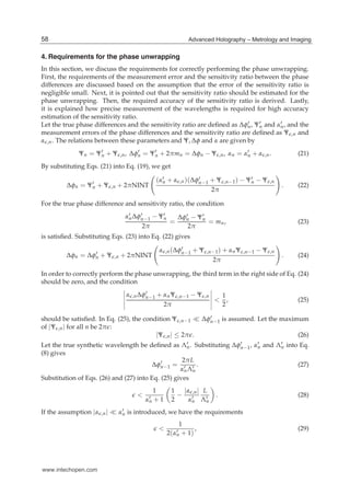
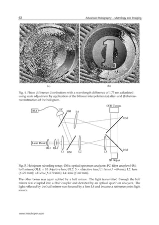
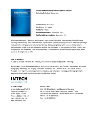
(a) Ψ1 (b) Ψ2 (c) Ψ3
(d) Ψ4 (e) Ψ5 (f) Ψ6
(g) Ψ7 (h) Ψ8 (i) Ψ9
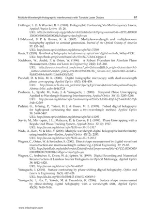
Fig. 8. Phase differences.
The central wavelength was obtained through the calculation of the center of gravity in the
spectrum distribution measured using the optical spectrum analyzer.
Ten holograms for phase difference extraction were chosen from the holograms. The phase
differences Ψn were extracted from the object images reconstructed from the holograms with
wavelengths λn. Figure 8 shows Ψn. It can be seen in Fig. 8 that the phase differences
have a salt-and-pepper noize produced by speckle noize. As shown in later, the noize can be
suppressed by image processing method such as smoothing and median filtering (Yamaguchi
(2001); Yamaguchi et al. (2006)).
The unwrapped phase differences Δφn were retrieved by the recursive calculations of Eq. (19).
The synthetic wavelengths were calibrated (Wada et al. (2008)) by the comparison between
the phase differences and the object height measured by using a slide caliper. The calibrated
synthetic wavelengths were Λ1 = 129.1mm, Λ2 = 34.02mm, Λ3 = 11.47mm, Λ4 = 8.593mm,
Λ5 = 4.914mm, Λ6 = 2.849mm, Λ7 = 1.380mm, Λ8 = 0.9061mm, Λ9 = 0.4637mm.
The object profile was obtained using Δφn. Since the incident angle θ for the object
illumination was equal to zero, L = 2h and
h =
ΛnΔφn
4π
. (36)
Because Δφ1 = Ψ1 and a phase difference within (−π, π] corresponds to a object height within
(−Λn/4, Λn/4], a measurable step height is Λ1/4 = 32 mm. The object height distributions
64 Advanced Holography – Metrology and Imaging
www.intechopen.com](https://image.slidesharecdn.com/intech-multiplewavelengthholographicinterferometrywithtunablelaserdiodes-170522204747/85/In-tech-multiple-wavelength_holographic_interferometry_with_tunable_laser_diodes-12-320.jpg)

Multiple-wavelength holographic interferometry uses tunable laser diodes to measure large step heights with high accuracy. Holograms are recorded at different wavelengths, generating phase differences with synthetic wavelengths from 0.4637 mm to 129.1 mm. The 129.1 mm wavelength allows measuring a 32 mm step height, while the 0.463 mm wavelength provides 0.01 mm measurement accuracy. Recursive calculations using phase differences from multiple wavelengths eliminate 2π ambiguities, enabling measurement of the 32 mm step with 0.01 mm accuracy. Precise knowledge of the recording wavelengths is required for correct phase unwrapping.