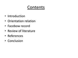
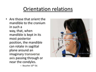
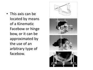
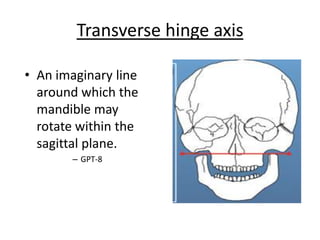
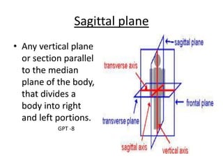
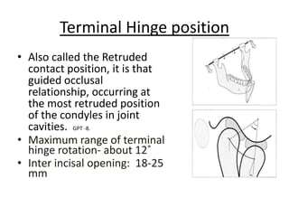
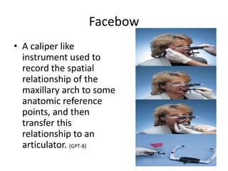
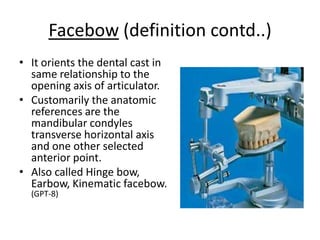
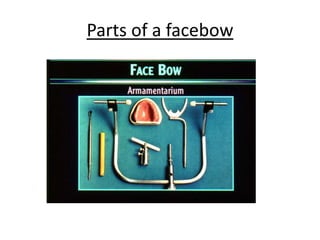
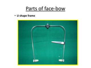
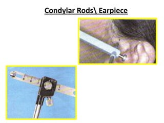
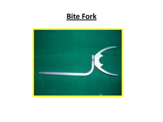
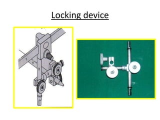
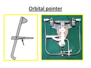
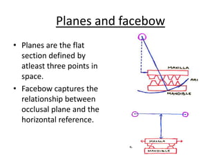
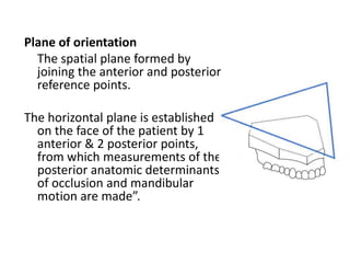
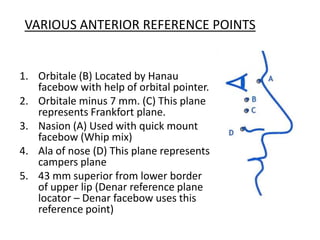
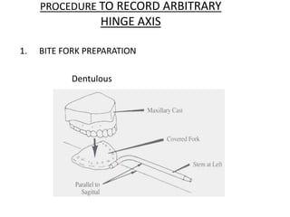
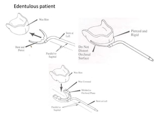
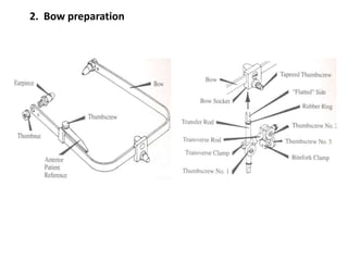
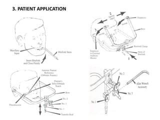
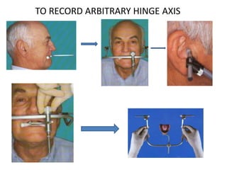
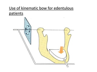
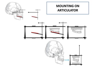
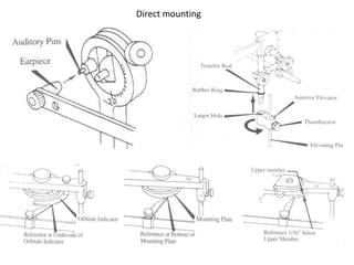
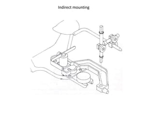
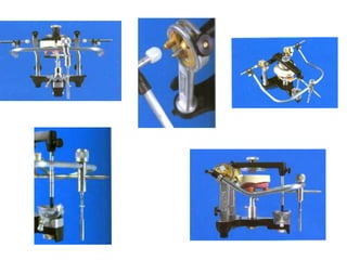
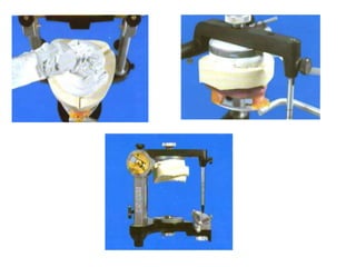
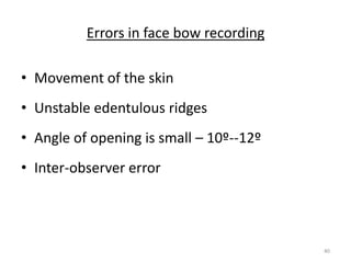
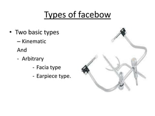
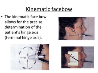
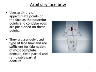
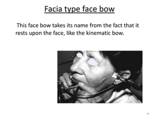
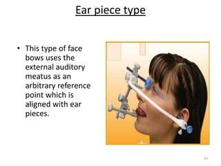
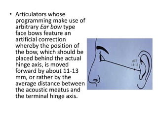
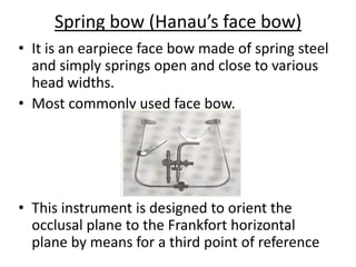
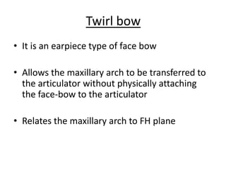
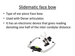
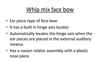
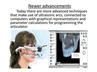
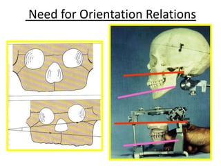
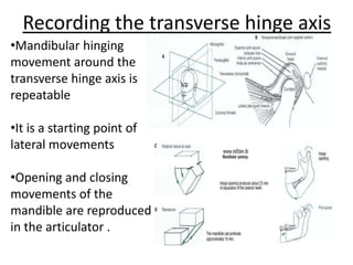
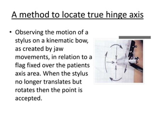
This document provides an overview of orientation relations and facebows. It defines key terms like jaw relation, orientation relation, and facebow. It describes the transverse hinge axis and sagittal plane. It discusses different types of facebows like kinematic, arbitrary, and earpiece facebows. It covers the procedure for taking a facebow record and potential errors. The document also reviews literature on controversies around locating the hinge axis and accuracy of arbitrary vs kinematic facebows. It provides a brief history of the development of facebow instruments over time.


![CTEV [ clubfoot] DR ARUN LAL ,DR MOHAMED ASHRAF travancore medical college k...](https://cdn.slidesharecdn.com/ss_thumbnails/ctevclubfootdrarunlaldrmohamedashraftravancoremedicalcollegekollamkeralaindia-260208063247-18fc466c-thumbnail.jpg?width=640&height=640&fit=bounds)


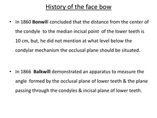
![ONFH[AVN HIP] -TRIPLE REGIME -A NOVAL SURGICAL CONCEPT .pptx](https://cdn.slidesharecdn.com/ss_thumbnails/onfhavnhip2026koaconcalicutdrgokuldevdrmashraf-260210064517-213ec005-thumbnail.jpg?width=640&height=640&fit=bounds)

