Download to read offline
![Proceedings of the International Conference on Emerging Trends in Engineering and Management (ICETEM14)
30 – 31, December 2014, Ernakulam, India
99
HARDWARE EFFICIENT SINGULAR VALUE
DECOMPOSITION IN MIMO-OFDM SYSTEM
Rajeswari S, Prathibha Varghese
ECE Department, SNGCE, Kolenchery, India
ABSTRACT
This paper presents an adaptive hardware design for computing Singular Value Decomposition (SVD) of the
radio communication channel characteristic matrix and is suitable for computing the SVD of a maximum of 4×4 real-
value matrices used in (multiple input Multiple output) MIMO-OFDM(orthogonal frequency division multiplexing)
standards, such as the IEEE 802.11n applications.Hence the data is transmitted without any interference from the
transmitting antenna. Also the data obtained is more reliable. The proposed method is able to deal with any matrix size
implementation and is able to deal with several channel matrices. The information of the right singular-vector matrix can
be fed back to the transmitter for beamforming to improve the error performance when facing the channel matrix. The
algorithms to decompose the channel matrix were implemented using the Spartan6 FPGA from Xilinx as the target
device. The implementation concentrates on utilizing the features of the FPGA to speed up operations and reduce the
area required by reducing the device utilization.Thus, reducing the effective cost.
Keywords: Hardware Decomposition; MIMO; OFDM;SVD; Throughput.
1. INTRODUCTION
Wireless access of high data rate is demanded by many applications. For higher data-rate transmissionmore
bandwidth is required. Hence in wireless communication SISO (single input and single output) is found to be insufficient
for use. Multiple transmit antennas can be used to form a MIMO system. Earlier SISO [1] [2] system were used for
transmission of data streams. But it offered less reliability and capacity. But G. J. Foschini, proved in his studies that,
compared with a SISO system, a MIMO system can improve the capacity by a factor of the minimum number of transmit
and receive antennas[3].Hence MIMO system became more important in the wireless communication system. But in a
MIMO system it became hard for the receiving section to obtain the correct data. Thus compared with a single-input
single-output (SISO) system, capacities of a MIMO system can be improved byminimum number of transmit and receive
antennas. But one of the disadvantages of the MIMO system is that, since there are more than single transmitters and
receiver, the receiving section may suffer from interference due to other transmitter antennas.Hence the above all
disadvantages of the paper was eliminated and the throughput and coverage of a MIMO system can be greatly enhanced
which was studied by I. E. Telatar From an information theoretical viewpoint, the use of SVD can be claimed as an
optimal solution. It is also shown that the application of the SVD technique has the highest throughput compared with
other MIMO signal processing techniques in the IEEE 802.11n systems. In many wireless [9] communication standards,
a MIMO system is usually combined with orthogonal frequency division multiplexing (OFDM) technology. OFDM is
becoming a very popular multi-carrier modulation technique for transmission of signals over wireless channels. As
mentioned above SVD is found to be applicable in MIMO-OFDM [3] [4] system in order to obtain high throughput and
enhance system performance. Its application is found to be mainly in the wireless communication systems. One of the
INTERNATIONAL JOURNAL OF ELECTRONICS AND
COMMUNICATION ENGINEERING & TECHNOLOGY (IJECET)
ISSN 0976 – 6464(Print)
ISSN 0976 – 6472(Online)
Volume 5, Issue 12, December (2014), pp. 99-105
© IAEME: http://www.iaeme.com/IJECET.asp
Journal Impact Factor (2014): 7.2836 (Calculated by GISI)
www.jifactor.com
IJECET
© I A E M E](https://image.slidesharecdn.com/hardwareefficientsingularvaluedecompositioninmimoofdmsystem-141216082303-conversion-gate02/85/Hardware-efficient-singular-value-decomposition-in-mimo-ofdm-system-1-320.jpg)
![Proceedings of the International Conference on Emerging Trends in Engineering and Management (ICETEM14)
30 – 31, December 2014, Ernakulam, India
99
HARDWARE EFFICIENT SINGULAR VALUE
DECOMPOSITION IN MIMO-OFDM SYSTEM
Rajeswari S, Prathibha Varghese
ECE Department, SNGCE, Kolenchery, India
ABSTRACT
This paper presents an adaptive hardware design for computing Singular Value Decomposition (SVD) of the
radio communication channel characteristic matrix and is suitable for computing the SVD of a maximum of 4×4 real-
value matrices used in (multiple input Multiple output) MIMO-OFDM(orthogonal frequency division multiplexing)
standards, such as the IEEE 802.11n applications.Hence the data is transmitted without any interference from the
transmitting antenna. Also the data obtained is more reliable. The proposed method is able to deal with any matrix size
implementation and is able to deal with several channel matrices. The information of the right singular-vector matrix can
be fed back to the transmitter for beamforming to improve the error performance when facing the channel matrix. The
algorithms to decompose the channel matrix were implemented using the Spartan6 FPGA from Xilinx as the target
device. The implementation concentrates on utilizing the features of the FPGA to speed up operations and reduce the
area required by reducing the device utilization.Thus, reducing the effective cost.
Keywords: Hardware Decomposition; MIMO; OFDM;SVD; Throughput.
1. INTRODUCTION
Wireless access of high data rate is demanded by many applications. For higher data-rate transmissionmore
bandwidth is required. Hence in wireless communication SISO (single input and single output) is found to be insufficient
for use. Multiple transmit antennas can be used to form a MIMO system. Earlier SISO [1] [2] system were used for
transmission of data streams. But it offered less reliability and capacity. But G. J. Foschini, proved in his studies that,
compared with a SISO system, a MIMO system can improve the capacity by a factor of the minimum number of transmit
and receive antennas[3].Hence MIMO system became more important in the wireless communication system. But in a
MIMO system it became hard for the receiving section to obtain the correct data. Thus compared with a single-input
single-output (SISO) system, capacities of a MIMO system can be improved byminimum number of transmit and receive
antennas. But one of the disadvantages of the MIMO system is that, since there are more than single transmitters and
receiver, the receiving section may suffer from interference due to other transmitter antennas.Hence the above all
disadvantages of the paper was eliminated and the throughput and coverage of a MIMO system can be greatly enhanced
which was studied by I. E. Telatar From an information theoretical viewpoint, the use of SVD can be claimed as an
optimal solution. It is also shown that the application of the SVD technique has the highest throughput compared with
other MIMO signal processing techniques in the IEEE 802.11n systems. In many wireless [9] communication standards,
a MIMO system is usually combined with orthogonal frequency division multiplexing (OFDM) technology. OFDM is
becoming a very popular multi-carrier modulation technique for transmission of signals over wireless channels. As
mentioned above SVD is found to be applicable in MIMO-OFDM [3] [4] system in order to obtain high throughput and
enhance system performance. Its application is found to be mainly in the wireless communication systems. One of the
INTERNATIONAL JOURNAL OF ELECTRONICS AND
COMMUNICATION ENGINEERING & TECHNOLOGY (IJECET)
ISSN 0976 – 6464(Print)
ISSN 0976 – 6472(Online)
Volume 5, Issue 12, December (2014), pp. 99-105
© IAEME: http://www.iaeme.com/IJECET.asp
Journal Impact Factor (2014): 7.2836 (Calculated by GISI)
www.jifactor.com
IJECET
© I A E M E](https://image.slidesharecdn.com/hardwareefficientsingularvaluedecompositioninmimoofdmsystem-141216082303-conversion-gate02/75/Hardware-efficient-singular-value-decomposition-in-mimo-ofdm-system-1-2048.jpg)
![Proceedings of the International Conference on Emerging Trends in Engineering and Management (ICETEM14)
30 – 31, December 2014, Ernakulam, India
100
advantages of the MIMO-OFDM system is that it is able to obtain a reliable data.Many traditional methods of SVD[2]
were found to be less advantageous due to its low throughput and with higher hardware utilization and moreover earlier
methods of SVD supported only 4×4matrices. Hence the proposed method of SVD[6] is such that it able to deal with
hundred of channel matrices as possible which reduces the decomposing latency and also a reconfigurable architecture
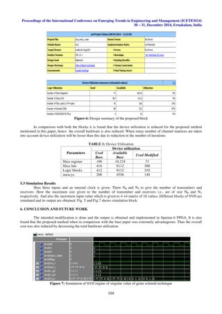
for all antenna configuration.
2. SVD TECHNIQUE
Consider a MIMO system with NT transmitter and NR receiver antennas. The baseband, discrete-time
equivalentmodel is written by y= Hx+ z, where value of H is thecomplex channel matrix, z is the Gaussian noise vector,
xis the transmitted data vector, and yis the received data vector. If decomposition [7] [8] is done in the channel matrix H
by the SVD technique, i.e., H= u∑vH
where U and V areleft singular matrix andright singular matrix,respectively.Both U
and V are unitary matrices and ∑ is diagonal matrix with only real and nonnegative main diagonal entries. The entry (i ,i)
of ∑ denotes the i th largest value σi, which is the singular value with 1 ≤ i ≤ min(NR,NT). The channel between x’and y’
can be written as:
y’
=UH
y=UH
(Hx+z)=UH
(HVx’
+ z’
)= ∑x’ + z’ (1)
Figure 1: MIMO modelling
Here x׳is the symbol vector such that x = Vx’ and the received signal y is multiplied by UH
as shown in the above Fig 1.
Singular Value Decomposition (SVD) of the channel characteristic matrix is used in pre-coding, equalization
and beamforming for MIMO and OFDM communication systems (e.g. IEEE 802.11n) to efficiently arrange the setup of
the data streams. The SVD problems of MIMO and OFDM systems such as the IEEE 802.11n standard are
computationally intensive and complex. Singular value decomposition is an optimal way to extract spatial multiplexing
gains in MIMO channels. SVD can be represented as a product of and are unitary, and is a diagonal matrix.SVD can be
also viewed as a composition of three operations: a rotation, a scaling operation, and another rotation. When the channel
matrix is partially known to the transmitter, the optimal strategy is to transmit independent streams in the directions of
the eigenvectors.
Projection of modulated symbols onto matrix essentially directs the transmit symbols along eigen modes of the
fading channel. If the receive signal is post-processed by rotatedorthogonally. Data streams can be send independently
through the spatial sub-channels withgains corresponding to the entries in the matrix. At the receiver, data streams arrive
orthogonally without interference between the streams.
3. PROPOSED SYSTEM
The SVD design block consists of various blocks to obtain the values of ui ,vi, σi .Various block included here
are zero padding,deflation unit ,update unit ,partial update unit, singular calculation unit.In zero padding block it is
extended to the original channel matrix of size 4×4.From the zero padding block semidefinite matrix value R1 is
calculated. And from the deflation unit values of Ri is obtained. And each value of update unit is fed back to the deflation
unit. This is used to calculate ( wi,λi) .The deflation process cancels the information of the pair ( wi,λi) for the estimation
of next pair ( wi+1,λi+1). The blind-tracking and deflation process continues until all pairs are estimated. The above
mentioned process is established via the adaptive blind tracking algorithm.After finding different values sequentially, this
values are fed to the partial update unit, sigma unit to find the values u, v σ. But these values are for the square
matrix.For a non-square matrix, theremaining values are obtained by using gram Schmidt unit.](https://image.slidesharecdn.com/hardwareefficientsingularvaluedecompositioninmimoofdmsystem-141216082303-conversion-gate02/85/Hardware-efficient-singular-value-decomposition-in-mimo-ofdm-system-2-320.jpg)
![Proceedings of the International Conference on Emerging Trends in Engineering and Management (ICETEM14)
30 – 31, December 2014, Ernakulam, India
101
Figure 2: Architectural unit of the proposed system
But these values are for the square matrix. The MIMO channel can be treated as singular valued = min (NR,NT)
independent parallel Gaussian subchannels. The ith
subchannel has the gain being σi. Hence, the transmitter can send
independent data streams across these parallel subchannels without any interference from an antenna. Values σ1, σ2, . . .,
σd are called the singular values .The column vectors of V(i.e., v1, v2, . . . , vNT) are the right singular vectors of H, and
the column vectors of U(i.e., u1, u2, . . . , uNR) are the left singular vectors of H.
3.1 Zero Padding
In a MIMO system, assume that the maximum number transmitter and receiver antennas in the system is
MR and MT respectively. This means that, there is possibly MR•MT different sizes of channel matrices.Therefore, a
scheme which is reconfigurable is proposed to support all antenna configurations [6]. Hence an SVDengine is designed
to support the maximum channel size. If the size of a given matrix is NR×NT the extended channel matrix is MR×MT.After
extending the original channel matrix by MR×MT inserting zeros, channel matrix extended to by inserting zeros, and the
multiplexer is used to construct the positive semi-definite matrix R1The positive semidefinite matrix R1 is estimated by a
moving average of the recent received signal vectors. In many MIMO OFDM-based standards, the channel matrix His
already known by channel estimation.
R1= {HH
H , NR ≥ NT}
or (2)
R1= {HHH ,
NR <NT }
With this definition of R1, still the same update and deflation process is used to find the pairs (wi,λi) sequentially.
3.2 Deflation Unit
The deflation process is used to estimate the pair (wi, λi). The deflation process cancels the information of the
pair (wi, λi) for the estimation of next pair (wi+1,λi+1). In the deflation process, where d = min (NR,NT) and the ith
deflation
process is given by:
Ri+1=Ri–Wi(n+1)Wi(n+1)
H
i=1, 2 ,………(d-1) (3)
Only the semidefinite matrix is calculated from this block. Remaining value, i.e, Ri is found sequentially in the
deflation unit post adaptive blind tracking algorithm. Deflation process continues until all pairs are estimated.ie all the
pairs are determined upto d-1. Value of ddepends on the size of the original channel matrix.
3.3 Updation and Sigma Calculator
This unit finds the different values of (wi, λi) Inthe ݅௧
update process, equation is:
Wi(n+1)=Wi(n)+µi(Ri-λi(n)I)Wi(n) (4)
λi(n+1)= Wi(n+1)
H
Wi(n+1) i=1, 2 ,…… (d-1) (5)
As in the Partial update unit, Wdand λdare derived by applying the update operation. From the observation, after
the (d−1) time deflation, the positive semi-definite matrix Rdcan be expressed as:
Rd=WdWd
H
(6)](https://image.slidesharecdn.com/hardwareefficientsingularvaluedecompositioninmimoofdmsystem-141216082303-conversion-gate02/85/Hardware-efficient-singular-value-decomposition-in-mimo-ofdm-system-3-320.jpg)
![Proceedings of the International Conference on Emerging Trends in Engineering and Management (ICETEM14)
30 – 31, December 2014, Ernakulam, India
102
Here the dth
singular value of the singular value is obtained as soon as the values are obtained .Here in this
block, sum of diagonal entries is calculated from the column of the matrix. And the value of is obtained by taking the
square root. Hence, the update operation for wd and λ dis unnecessary, where singular value is found directly and the
corresponding singular vectors by some simple operations.
σd=√tr(Rd) (7)
Thus the dth
singular value σ is obtained.
Figure 4: Updation and sigma calculator
3.4 Singular with Partial Update Unit
Compared to the paper [6], algorithm of SVD takes many iterations to calculate the different values in the
update unit, singular calculation and the partial update unit. So here the algorithm is modified in such a way that number
of iterations was less for calculating the different units as explained above. One of greatest advantage was that with the
modification in this algorithm the number of hardware units was also reduced. In singular calculation unit , it is used to
find the value of ui ,vi, σi values as mentioned in the paper[6].Hence dsingular values, of NRleft singular vectors, and NT
right singular vectors need to be find.And it depend on whether d = min(NR,NT) .But in this case singular vectors are
found upto (d-1) values are found for and have found that in the sigma calculator ,as a result of reducing the hardware.If
the channel matrix is square, it means that d= NR=NT.
Vd= Rd(:,1)/ ǁ Rd(:,1) ǁ (8)
Ud= HVd/ σd (9)
On the other hand, when NR<NT,Vd with Udis interchange and His changed to HH
.
Figure 3: Singular with partial update unit](https://image.slidesharecdn.com/hardwareefficientsingularvaluedecompositioninmimoofdmsystem-141216082303-conversion-gate02/85/Hardware-efficient-singular-value-decomposition-in-mimo-ofdm-system-4-320.jpg)
![Proceedings of the International Conference on Emerging Trends in Engineering and Management (ICETEM14)
30 – 31, December 2014, Ernakulam, India
103
3.5 Gram Schmidt Unit
For the case of non square channel matrix, assume that NR>NT,d=NTthere are still NR-NT unsolved left singular
vectors. The unresolved left singular values is, V(i.e., v1, v2, . . .,vNT) are the right singular vectors of H, On the other
hand, when NR<NT there are still NT -NR unsolved right singular vectors U(i.e., u1, u2, . . . , uNR) are the left singular
vectors of H.
Wd+k=ek-∑(ek,ui).ui i=1, 2 ,….d+k-1 (10)
Ud+k=Wd+k / ǁWd+kǁ (11)
For the case of NR<NT replaceuiwith vi
Figure 5: Singular with partial update unit
4. REQUIREMENTS
4.1 Software and Hardware Requirements
The hardware implementation is done in Xilinx ISE 14.1 and the project is implemented in Spartan 6 with the
help of VHDL (verilog hardware description language).Required files are synthesized in the Xilinx device. Spartan 6
Family device XC6SLX45 with the package CSG324 is used for its hardware implementation
5. RESULT ANALYSIS AND DISCUSSION
The waveforms of the various parts of the block is simulated and its various waveforms are also observed. The
comparison is studied in accordance with the design summary generated in the Xilinx device.
5.1 Design Summary
Design summary allows you to quickly access design overview information,reports. By default, the design
summary displays information specific to the targeted device and software tool. Here from the design summary generated
both from base[6] and the modified block. These two blocks are compared and studied .Below shows the estimated value
and design summary of both modified block and the base block. The design gives an overall view of different units used
for the implementation of svd device.
5.2 Comparison
In comparison of the two blocks it is seen that the number of luts used, memory slice registers, logic blocks used
and everything is reduced. Here the design summary is generated for the algorithm which is implemented and also for the
already implemented SVD [6].](https://image.slidesharecdn.com/hardwareefficientsingularvaluedecompositioninmimoofdmsystem-141216082303-conversion-gate02/85/Hardware-efficient-singular-value-decomposition-in-mimo-ofdm-system-5-320.jpg)
![Proceedings of the International Conference on Emerging Trends in Engineering and Management (ICETEM14)
30 – 31, December 2014, Ernakulam, India
105
Figure 8: Simulation of SVD engine of Partial update unit
These design strategies enable the use of SVD to be effectively applied to high throughput wireless
communication system and also with effectively reducing the hardware units, the chip area required is reduced. Thus
leading to the overall reduction in hardware cost.
Future works for this paper can be done for different transmit and receive antennae sets such as 8x8, 16x16
matrices. And also further work can be done so that high throughput is achieved .Also more refined work can be done to
reduce the decomposing period require to calculate the different values of the SVD further hardware reduction is also
another arena where hardware utilization is reduced.
7. ACKNOWLEDGMENT
The success accomplished in this project would not have been possible without the timely help and guidance
rendered by many people to whom I feel obliged and grateful.
First of all I express my deep gratitude to ALMIGHTY the supreme guide for bestowing his blessings upon us
in my entire endeavor.
I am extremely grateful to Asst.Prof, PRATHIBHAVARGHESE guide of my project for her valuable guidance
and encouragement throughout my humble endeavor
REFERENCES
[1] S.M Alamouti, “A simple transmit diversity technique for wireless communications,” IEEE j.Sel Areas
Communication, vol. 16, no. 8, pp. 1451-1458, oct 1998.
[2] A.Goldsmith,S.A. Jafar,N. Jindal ans S. Viswanath,”Capacity limits of MIMO channels,” IEEE j.Sel Areas
Communication, vol. 21,no. 5,pp. 684-702, Jun 2003.
[3] H. Sampath,S. Talwar.J. Talwar,V. Erceg and A. Paulraj,”A fourth generation MIMO OFDM: Broadband
wireless system: Design, performance, and field trial results,” IEEE Commun Mag., vol. 40,no. 9,pp. 143-149,
sep 2002.
[4] Minn and N. Al-Dhahir, “Optimal training signals for MIMO OFDM channel estimation,” IEEE wireless
Communication, vol. 5,no. 5,pp. 1158-1168, may 2006.
[5] G. Foschini, “Layered space-time architecture for wireless communication in a fading environment when using
multi-element antennas,” BellLabs Tech.J., pp. 41–59, 1996.
[6] Yen-LiangChen, Cheng-Zhou Zhan, Reconfigurable Adaptive Singular Value Decomposition Engine Design for
High Throughput MIMO-OFDM Systems IEEE transactions on very large scale integration systems 2013, Vol.
21, NO. 4, April 2013.
[7] D. Markovic, B. Nikolic and R. W. Brodensen, “Power and area minimization for multidimensional signal
processing,” IEEE J. Solid state circuits syst msg., Vol. 42, NO. 4, April 2007.
[8] A. Poon, D. Tse, and R. W. Brodersen, “An adaptive multi antenna transceiver for slowly flat fading channels,”
IEEE Trans. Commun., vol. 51, no. 11, pp. 1820–1827, Nov. 2003.
[9] T. K. Paul and T.Ogunfunmi, “Wireless LAN comes of age: Understanding the IEEE 802.11n amendment,”
IEEE Circuits Syst. Mag., vol. 8, no. 1, pp. 28–54, Jan. 2008.
[10] N.D. Hemkumar and J.R. Cavallaro. A systolic VLSI architecture for complex SVD. In Circuits and Systems,
1992. ISCAS ’92. Proceedings., 1992 IEEE International Symposium.
[11] Y.G.Li,J.H.Winters, and N.R.Sollenberger,“MIMO-OFDM for wireless communications: Signal detection with
enhanced channelestimation,” IEEE Trans. Commun., vol. 50.](https://image.slidesharecdn.com/hardwareefficientsingularvaluedecompositioninmimoofdmsystem-141216082303-conversion-gate02/85/Hardware-efficient-singular-value-decomposition-in-mimo-ofdm-system-7-320.jpg)

This document describes a hardware efficient method for performing singular value decomposition (SVD) in MIMO-OFDM systems. The proposed method uses an adaptive hardware design to compute the SVD of channel characteristic matrices up to size 4x4. It utilizes features of FPGAs like pipelining to speed up operations and reduce resource usage. The method first extends the channel matrix with zero padding. It then uses techniques like deflation, updating, and partial updating to sequentially estimate the singular values and vectors. For non-square matrices, remaining values are obtained via Gram-Schmidt orthogonalization. Simulation results show the proposed method reduces FPGA resource utilization compared to previous methods, lowering overall implementation costs.


![1687 1499-2008-601346[1]](https://cdn.slidesharecdn.com/ss_thumbnails/1687-1499-2008-6013461-131222110733-phpapp02-thumbnail.jpg?width=640&height=640&fit=bounds)