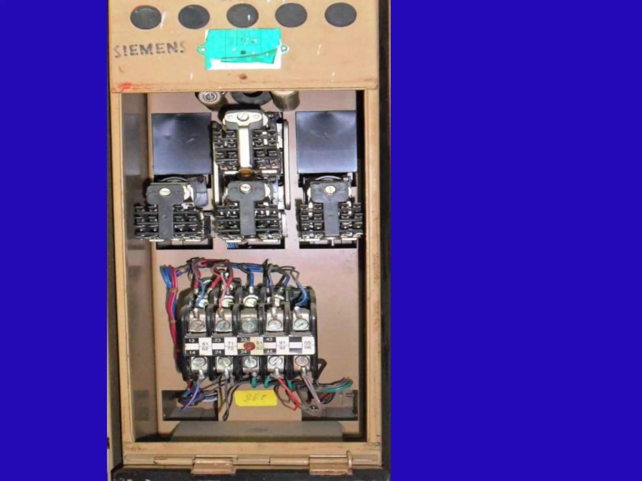
The document provides details about an electrical point machine. It discusses:
1. The point machine has a cast iron casing and cover that houses the motor, reduction gear, contact assembly, and locking/throw assembly.
2. The DC motor is a series split-field motor that operates on 110V DC and provides high initial torque. It has a reduction ratio of 20.8:1 to convert high-speed motor rotation to slower, higher-torque output.
3. A friction clutch between the motor and load protects the motor from overload and provides mechanical snubbing of the point movement.
That covers the key components and functions of the electrical point machine in under 3 sentences.
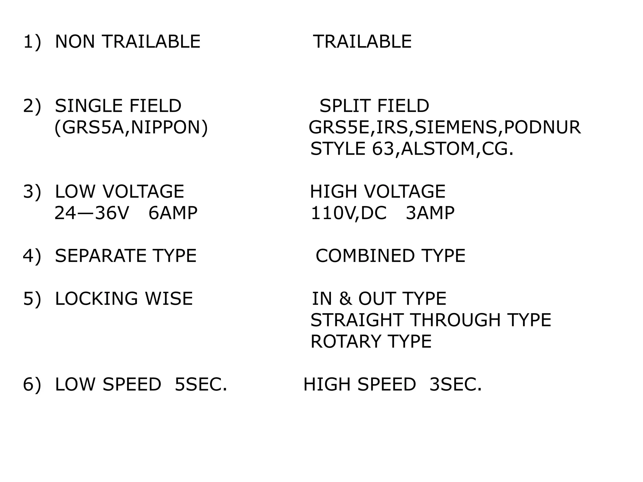
1) NON TRAILABLETRAILABLE
2) SINGLE FIELD SPLIT FIELD
(GRS5A,NIPPON) GRS5E,IRS,SIEMENS,PODNUR
STYLE 63,ALSTOM,CG.
3) LOW VOLTAGE HIGH VOLTAGE
24—36V 6AMP 110V,DC 3AMP
4) SEPARATE TYPE COMBINED TYPE
5) LOCKING WISE IN & OUT TYPE
STRAIGHT THROUGH TYPE
ROTARY TYPE
6) LOW SPEED 5SEC. HIGH SPEED 3SEC.
IRS POINT MACHINE
IRSPOINT MACHINE is rotary locking type point
machine and designed to comply with IRS specification
S-24/2000 and RDSO Dr.No.S10.800.
it is designed to operate all type of points /switches.
It is available in two model low stroke (143mm) and high
stroke (220mm)
It is non-trailable type point machine
5.
Sr
No
b
Description remark
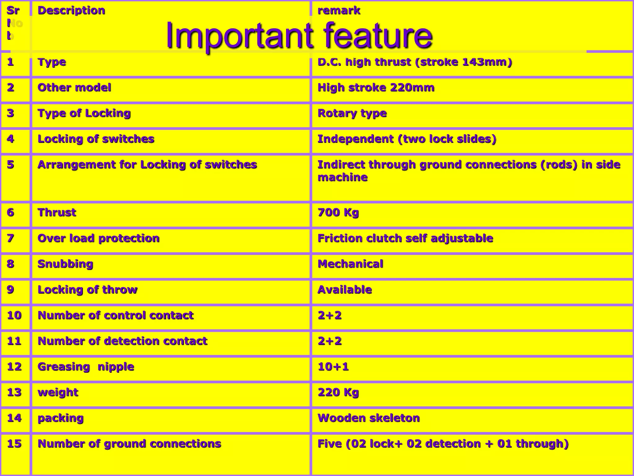
1 TypeD.C. high thrust (stroke 143mm)
2 Other model High stroke 220mm
3 Type of Locking Rotary type
4 Locking of switches Independent (two lock slides)
5 Arrangement for Locking of switches Indirect through ground connections (rods) in side
machine
6 Thrust 700 Kg
7 Over load protection Friction clutch self adjustable
8 Snubbing Mechanical
9 Locking of throw Available
10 Number of control contact 2+2
11 Number of detection contact 2+2
12 Greasing nipple 10+1
13 weight 220 Kg
14 packing Wooden skeleton
15 Number of ground connections Five (02 lock+ 02 detection + 01 through)
Important feature
6.
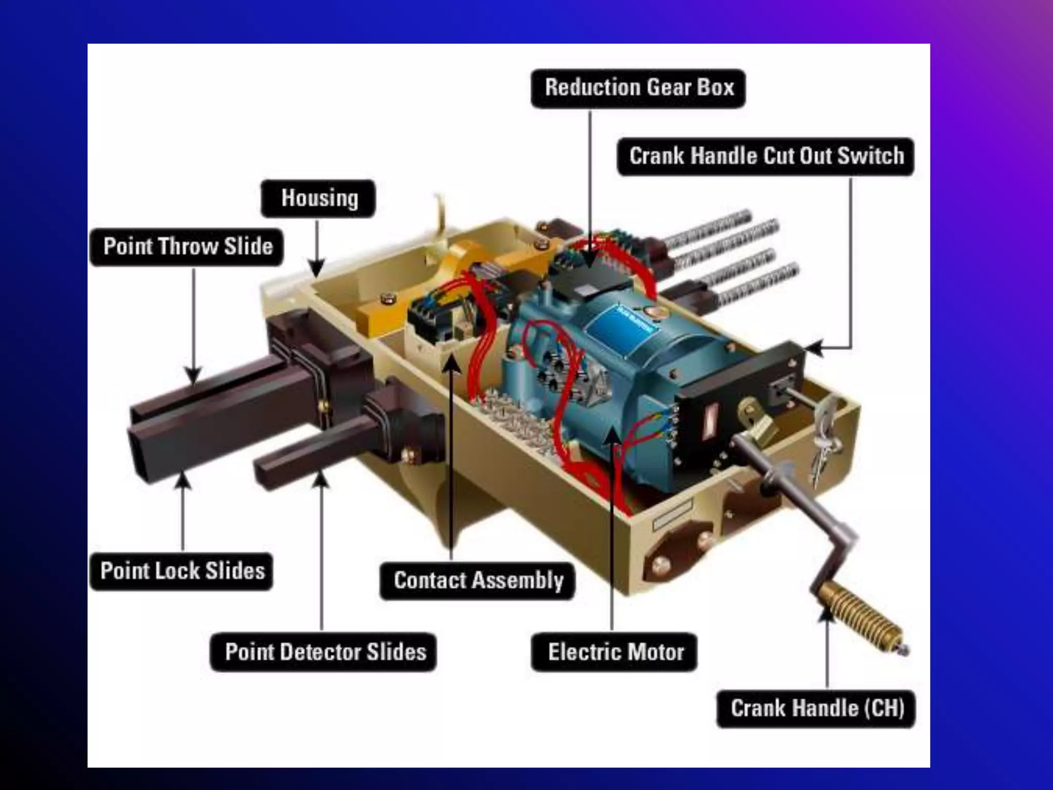
General Features ofpoint machine
The basic design of point machine generally
comprises of
Cast iron casing and cover with locking
arrangement
Motor
Reduction gear
Crank handle mechanism
Friction clutch
Contact assembly with spring loaded rollers and
Detection slides
Rotary to linear conversion mechanism
Locking and throw assembly
Cast iron case
accommodatesall the parts of point
machine
is made of cast iron and designed to fix all
parts at required place.
provide access to/ slots for different lock
and detection slides
facilitate fixing of machine on sleepers
Provides an arrangement to drain out
water/ oil in bottom of casting.
Provides cable entry.
24.
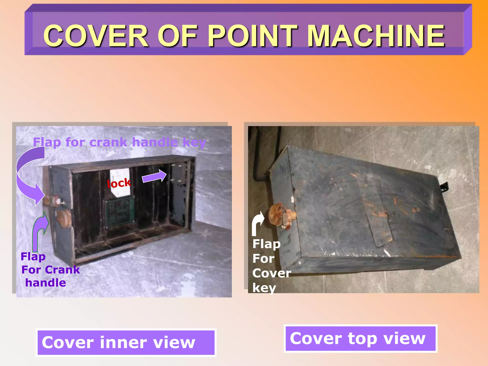
COVER OF POINTMACHINE
Made up of thick iron sheet and fixed on cast iron
casting (case)
Contain lock ( S&T maintainer's lock) on inner
side surface to lock it with cast iron casting
(case).
Secure all the parts of machine in weather proof
environment and prevents un-authorosed
interference.
Provides access only to nominated (ward
&feather) crank handle insertion.
All the apertures for keys and crank handle are
secured by flaps
All flaps has a locking arrangement
25.
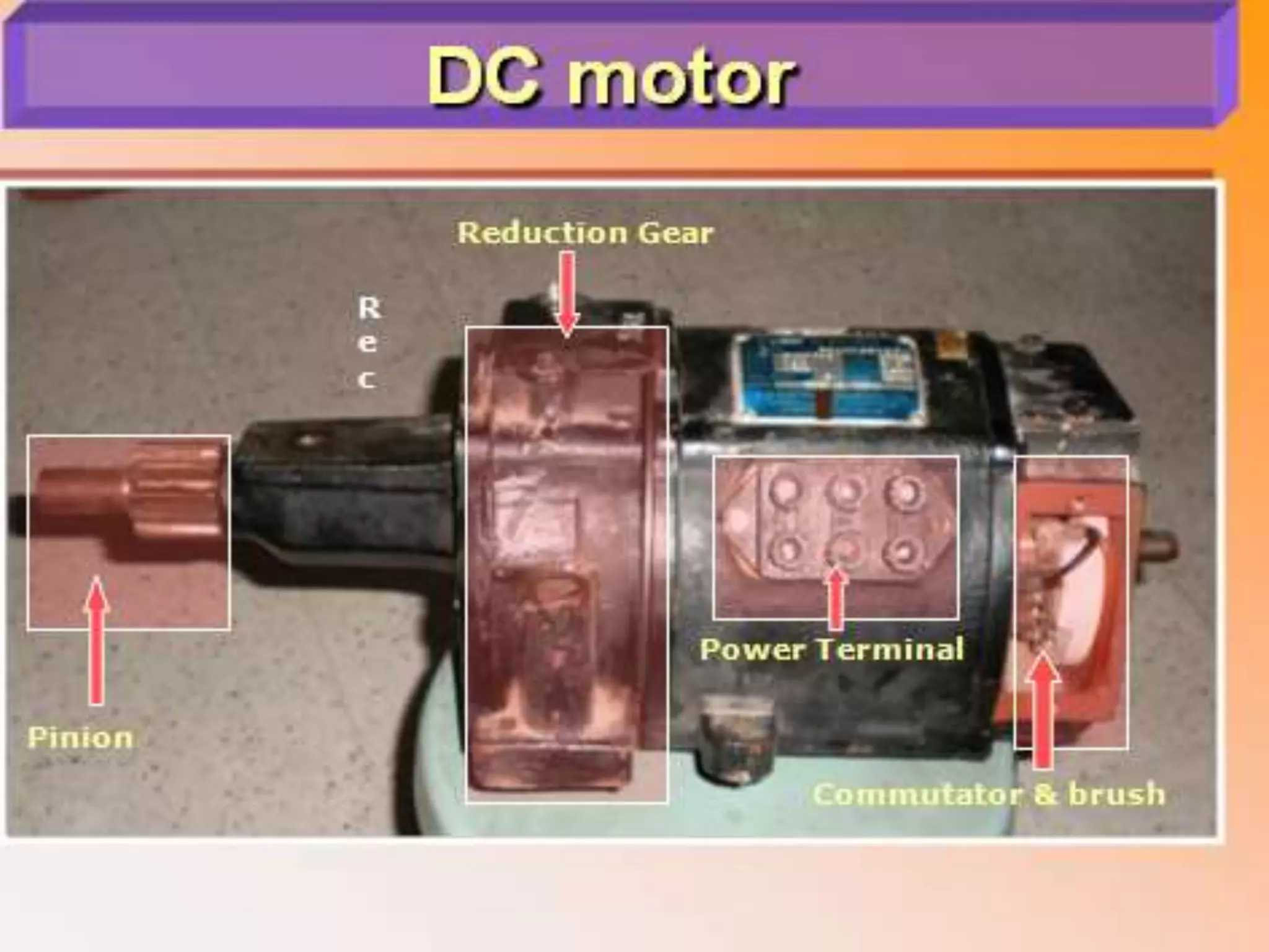
MOTOR
DC motorIRS: S 37 Motors for
Electric Point Machine.
shall comply with the requirements
of IRS: S 37 'Motor for Electric
Point machine.
Motor comprises of
1. crank handle cutout contact
assembly,
2. DC motor
3. reduction gear
26.
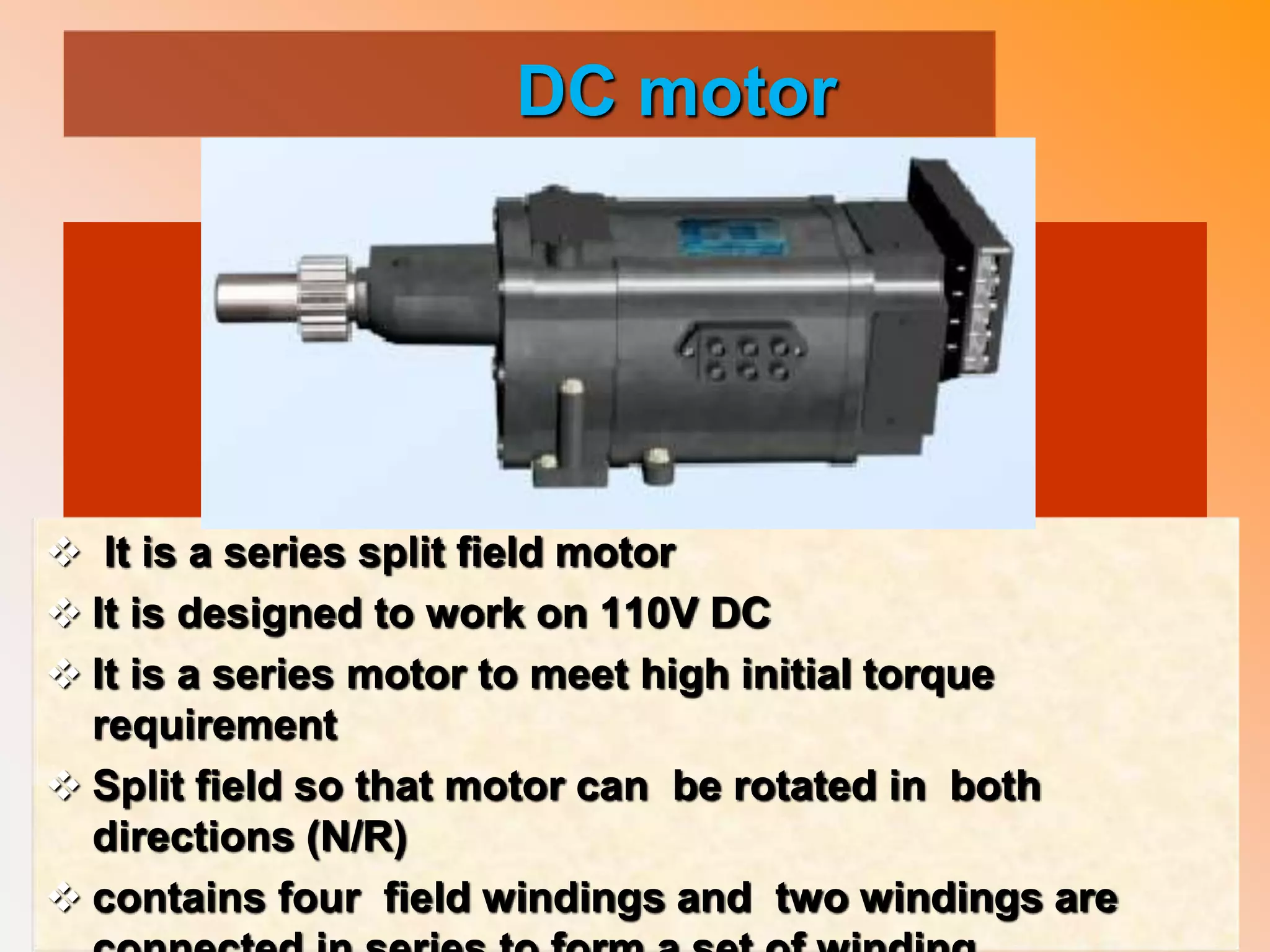
DC motor
Itis a series split field motor
It is designed to work on 110V DC
It is a series motor to meet high initial torque
requirement
Split field so that motor can be rotated in both
directions (N/R)
contains four field windings and two windings are
27.
CRANK HANDLE ANDCRANK
HANDLE MECHANISM
It allows Manual operation (without
power) of point
It require in case of failures of point/
point machine OR for the purpose of
maintenance of point machine.
It prevents simultaneous operation of
power as well as manual.
It contains.
1. CRANK HANDLE AND KEY
2. CRANK HANDLE CUTOUT CONTACT
ASSEMBLY
28.
CRANK HANDLE
This apparatusis used for
manual operation of point
machine
It is a “Z” shape structure
made of steel pipe and has
wooden handle on one end
to have better gripe.
Wards &feathers are
welded on other end of pipe
facilitates coding (insertion
of only to nominated crank
handle).
A stud is intrude in the
pipe, it get engage in
forked shaft of motor
Crank handle
Wooden
handle
Ward &
feather
29.
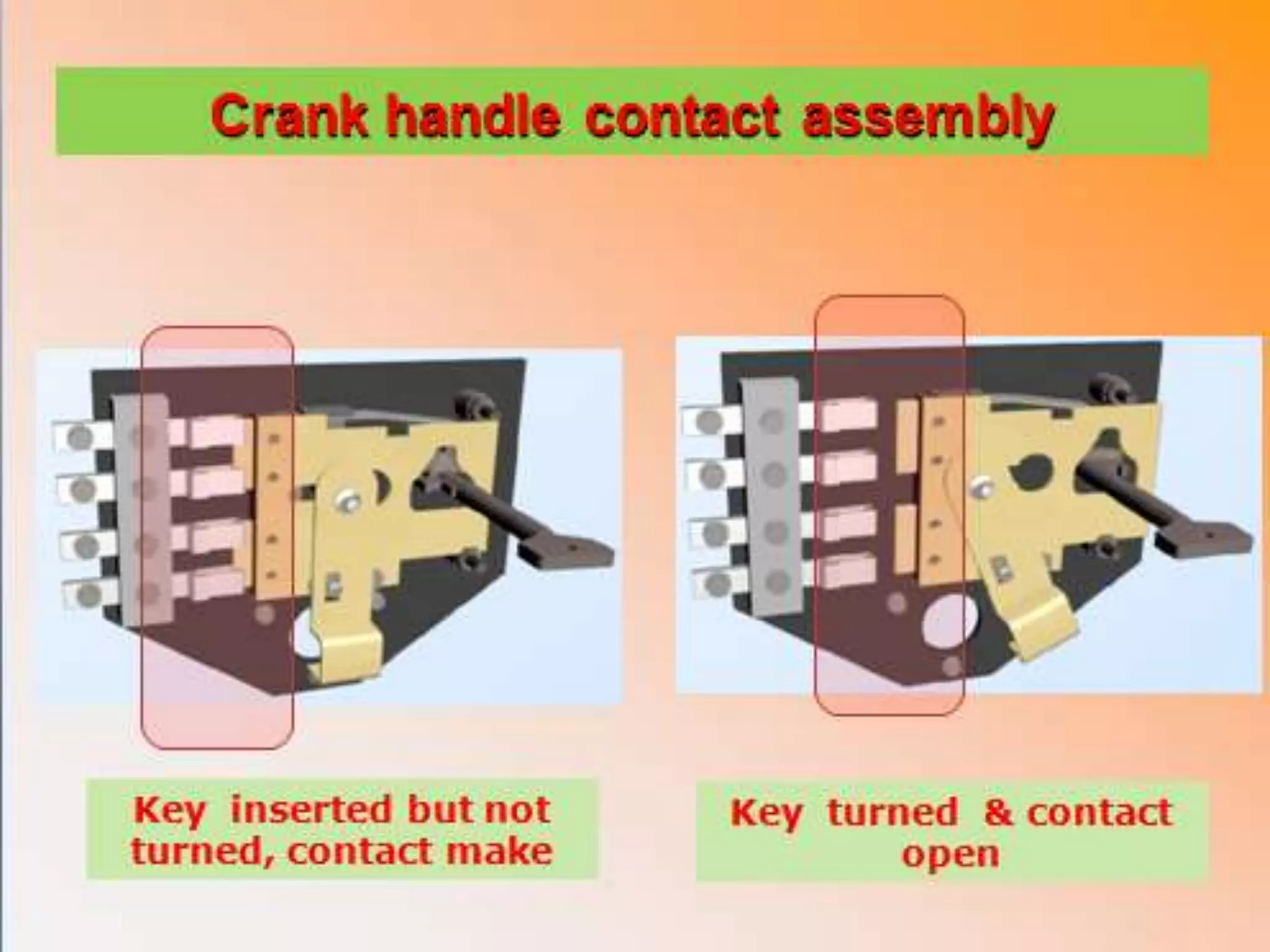
CRANK HANDLE CUTOUT
CONTACTASSEMBLY
It disallows simultaneous power and manual
operation of point machine to protect staff
performing crank handling.
Ordinarily crank handle can not be inserted in
machine
Turing of crank handle key permits/ allows insertion
of crank handle in the machine.
Turning of crank handle key isolates the negative
power path of motor.
It comprise of
1. Crank handle cutout contacts
2. flap cover plate
3. Crank handle key
30.
Crank handle cutoutcontacts
There are two sets of
contact
These contacts are
wired in negative path
of power supply to
motor.
Contacts break / open
with insertion and
turning of crank
handle key
Makes when crank
handle key is taken
out.
1
2
Crank handle contact closed & Flap in front of shaft
Crank handle contact open &Flap displaced & shaft visible
31.
Flap cover plate& key
controls the entry of crank handle in
the machine for manual operation
metal flaps attached to a lock
hangs/ placed in front of motor shaft
at the entry point of crank handle.
flap cover plate is displaced by
means of a crank handle key
The insertion and turning of crank
handle key
displace the flap cover plate to
allow insertion of crank handle
open crank handle cutout contacts.
Removal of the crank handle key
replaces flap cover in front of motor
shaft
makes the crank handle contact.
Crank handle key
32.
DC motor
isa series split field DC motor
Is designed to work on 110volt DC
Is a series motor to meet high initial torque
requirement
Is split field so that motor can be rotated in both
direction
contains four field windings and two windings are
connected in series to form a set of winding.
Use carbon brushes
33.
Sr
Nob
Description Remarks
1 TypeD.C. Series split field
2 Operating voltage 110 Volt DC (60 volt mini)
3 current 2 to 2.5 Amps
4 Thrust 700 Kg
5 Power 0.44KWt
6
Reduction ratio (in side
motor)
20.8 :1
7 AC immunity 160 , 300, 400 volts
8 Power supply terminals 03
9
Insulation grade of
windings
More than 10 M Ohms
Technical parameters of motor
34.
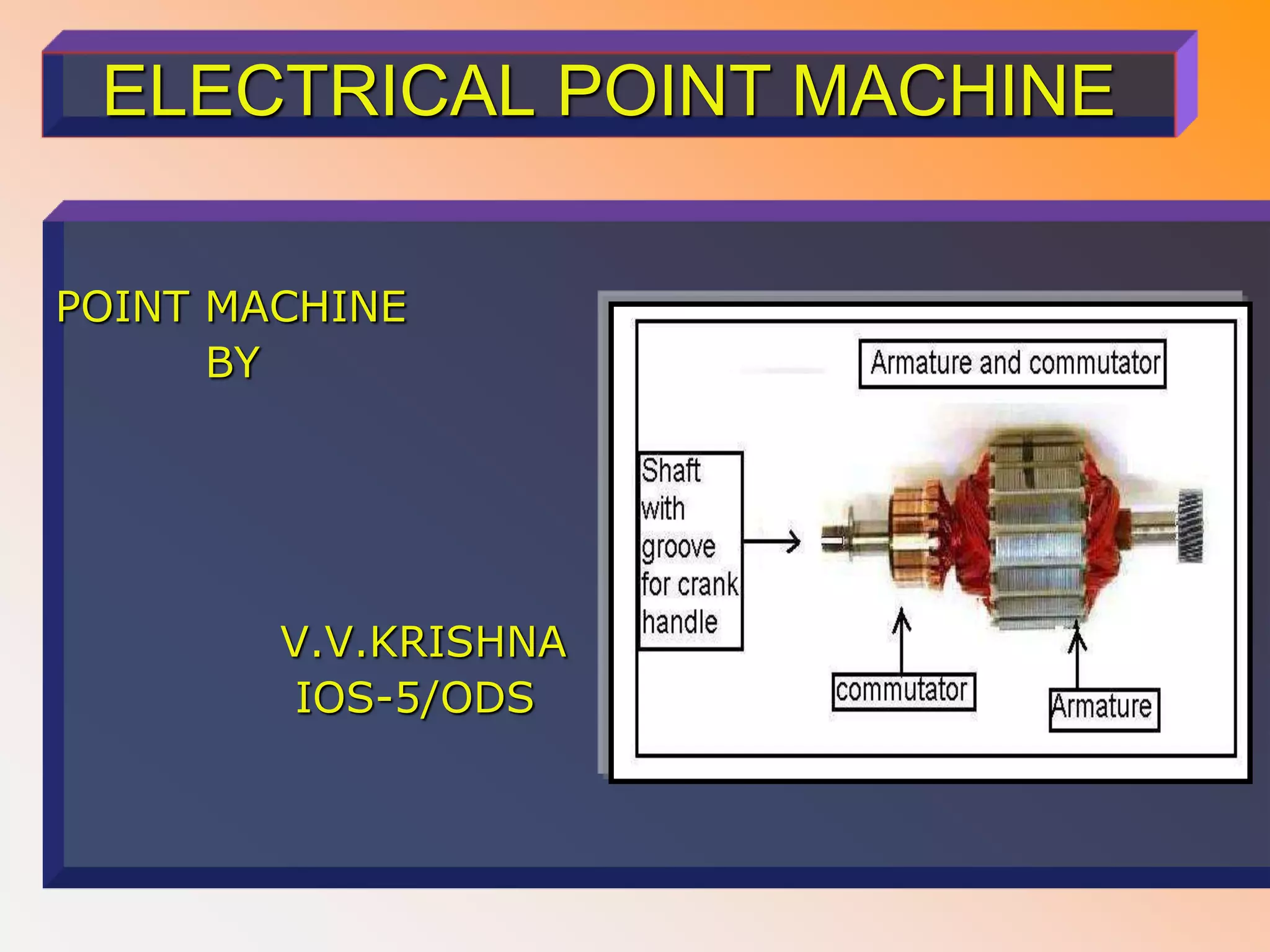
DC MOTOR mainparts
Armature and commutator
Field winding
Carbon brushes
Motor body
Groove for crank handle
35.
Armature and commutator
Functionof armature
To carry current crossing
the field thus creating
shaft torque
To generate an
electromotive force
Function of Commutator
Reverse the current in
moving coil of motor’s
armature and generate a
steady rotating force
(torque)
36.
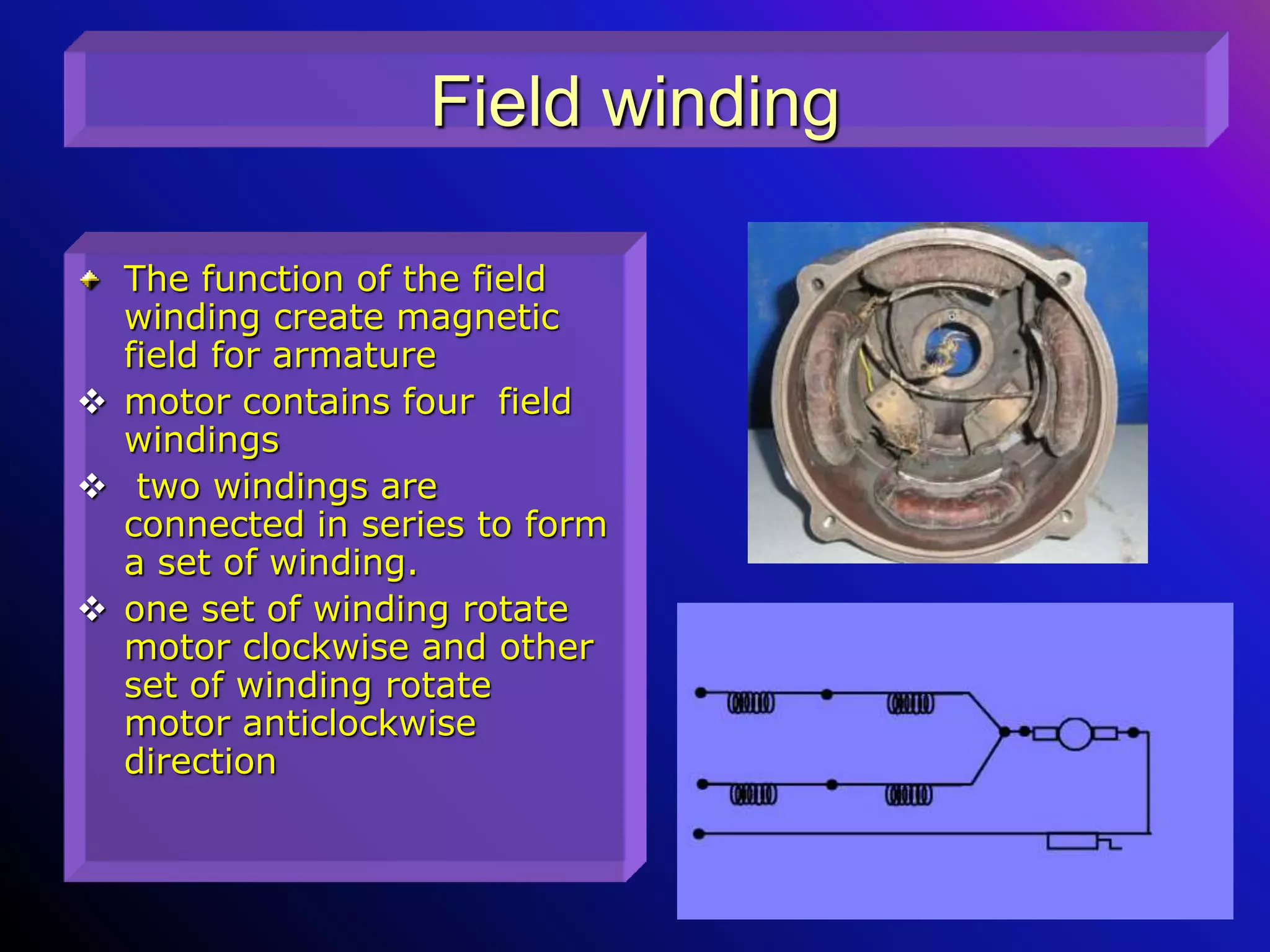
Field winding
The functionof the field
winding create magnetic
field for armature
motor contains four field
windings
two windings are
connected in series to form
a set of winding.
one set of winding rotate
motor clockwise and other
set of winding rotate
motor anticlockwise
direction
37.
Carbon brushes
Brush isrectangular carbon
block and spring loaded placed
in holder
Brush provides the electric
connectivity between field
windings and rotating
commutator
the holders should be mounted
a maximum of .125" above the
contact surface.
Proper functioning of the holder
depend upon,
Inside holder dimensions
equally Holder spacing
Holder angle (20 to 30 deg.)
Holder height
Spring force (4.0-6.0 PSI)
Electrical connections
Carbon brush
38.
Reduction gear
Itis trail of gears which provides reduction ratio 20.8:1
No of teeth on driven 75*75=5625
Reduction Ratio = ------------------------------------=20.8:1
No of teeth on driver 18*15=270
Reduction ratio provides a torque-speed conversion from a
higher speed motor to a slower but more forceful output.
Motor rotate at very high speed and Load can not be
directly placed on motor shaft.
Appropriate reduction gear ratio is used
to get require mechanical advantage/ thrust
to synchronized various functions
to get desire power as
39.
Friction Clutch
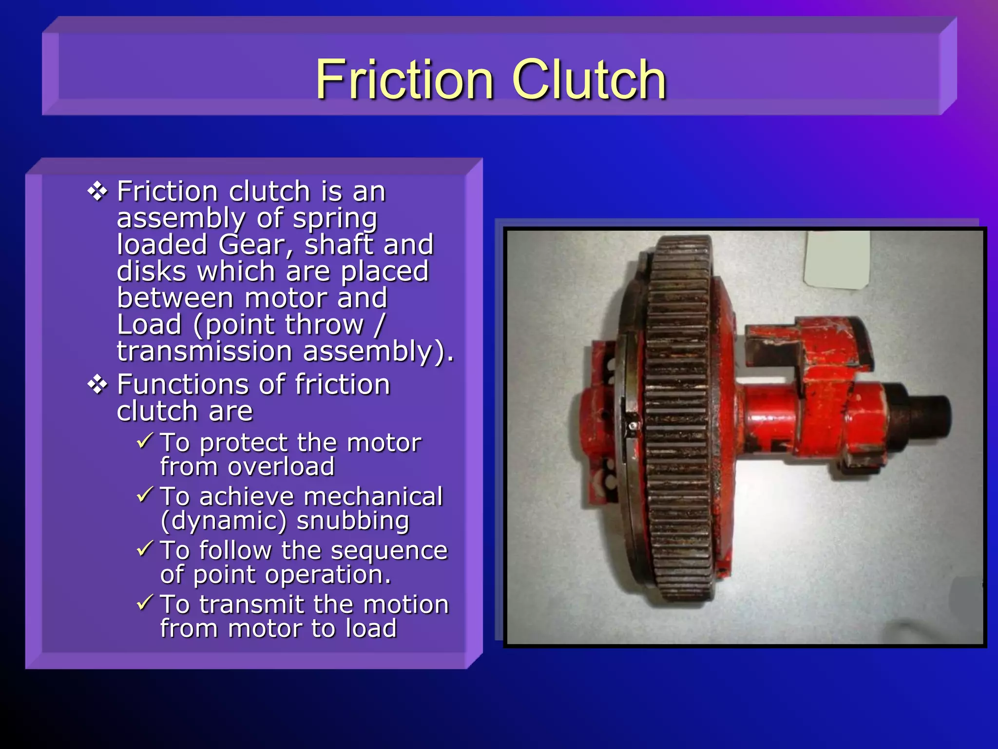
Frictionclutch is an
assembly of spring
loaded Gear, shaft and
disks which are placed
between motor and
Load (point throw /
transmission assembly).
Functions of friction
clutch are
To protect the motor
from overload
To achieve mechanical
(dynamic) snubbing
To follow the sequence
of point operation.
To transmit the motion
from motor to load
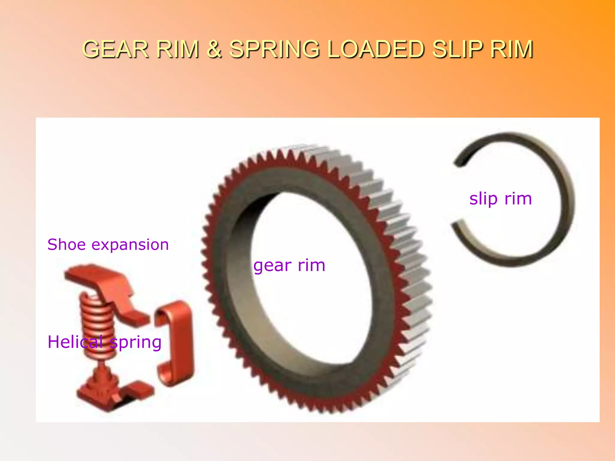
GEAR RIM &SPRING LOADED SLIP RIM
Shoe expansion
Helical spring
gear rim
slip rim
42.
Feature of frictionclutch
The friction clutch designed to
extend stroke (force) from motor to load (point)
if load is within Specified limit (700 Kg)
de-clutch (separate) motor and Load (point) if
load is more than Specified limit (700 Kg).
De-clutching of friction clutch can be adjusted to
suite Specified limit of load (700 Kg) by
loosening Or tightening spring.
Friction clutch require / needs an adjustment if
slipping current /obstruction current shall not be more
than 1.5 to 2 times of normal working current
difference between normal working current and
slipping current /obstruction current should not be less
than 0.5 Amps.
The friction clutch shall adjusted in workshop only (not
at site).
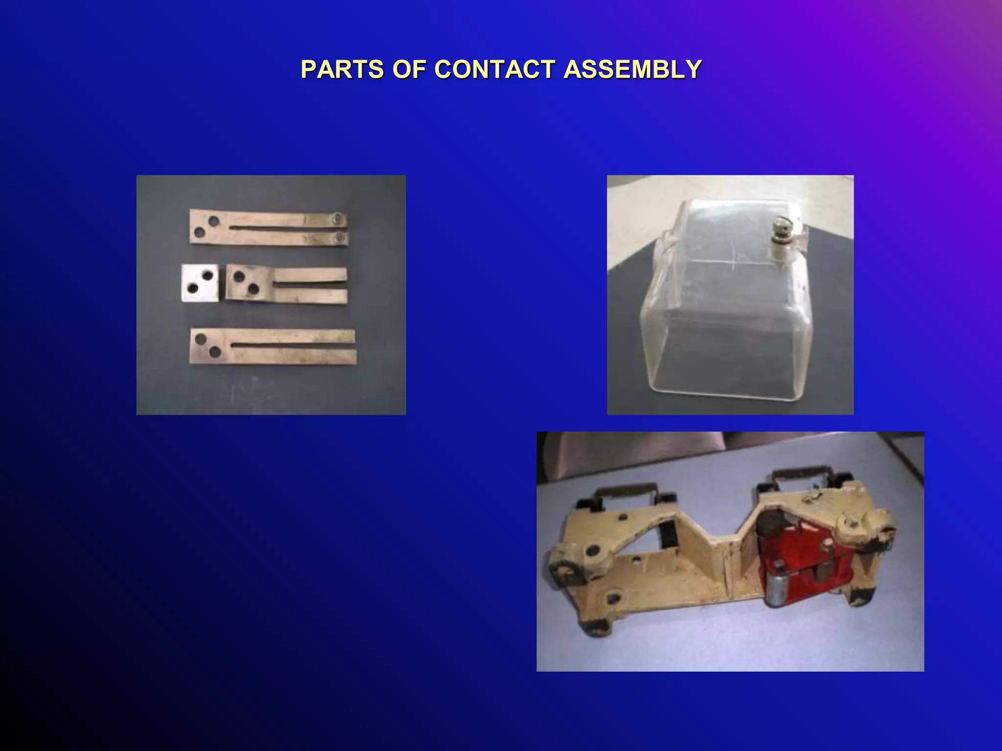
43.
Parts of frictionclutch
Friction clutch comprises of
Control disc
Lift out disc
Drive disc
Gear rim and slip rim
Shoe expansion (locking plate)
Helical spring
44.
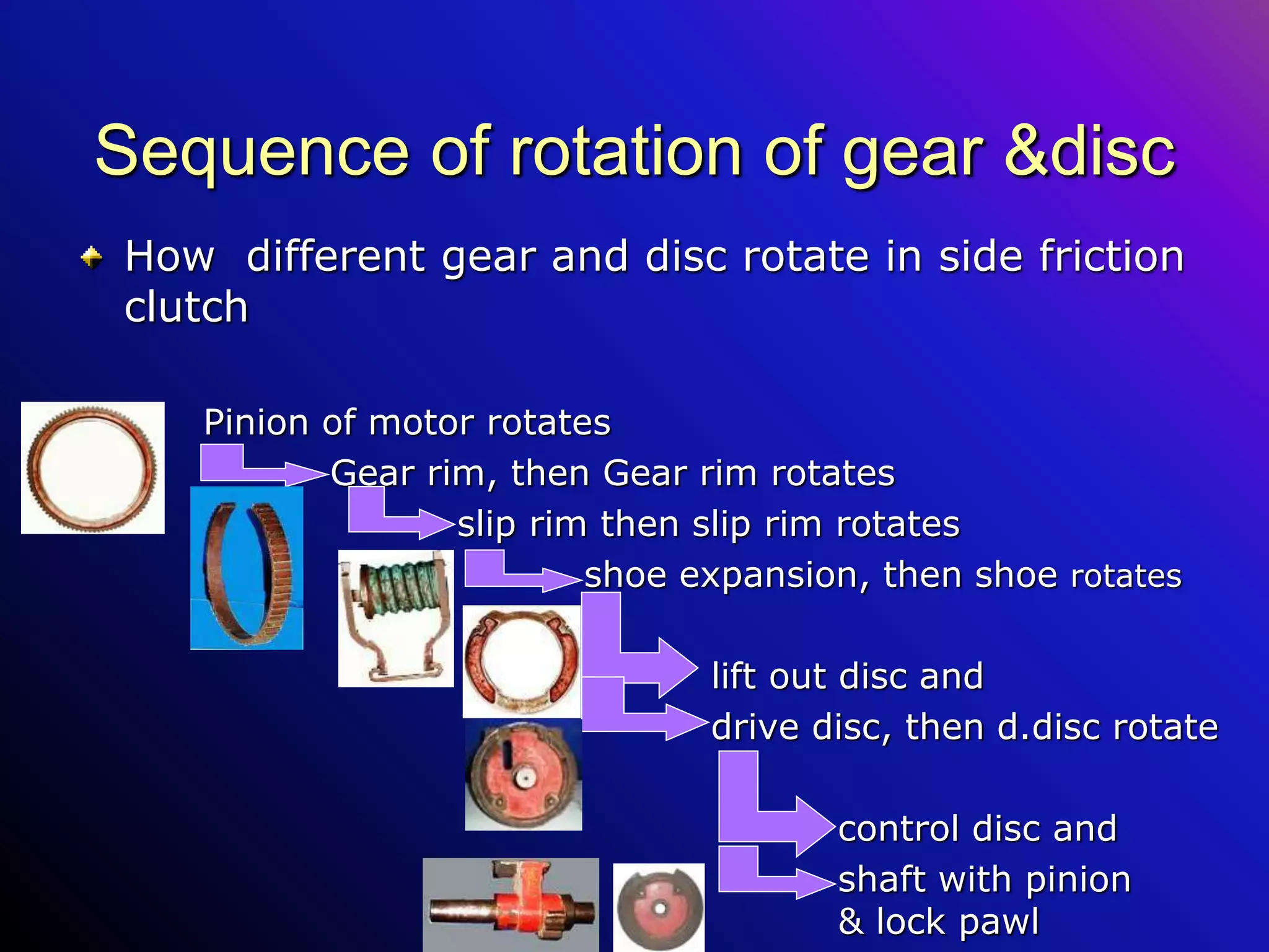
Sequence of rotationof gear &disc
How different gear and disc rotate in side friction
clutch
Pinion of motor rotates
Gear rim, then Gear rim rotates
slip rim, then slip rim rotates
shoe expansion, then shoe rotates
lift out disc and (3mm)
drive disc(12mm) then drive
disc rotates
control disc and shaft
with pinion & lock pawl
45.
Control disc
It isa circular disc
with(120mm) notch on
outer periphery
Edges of notch are vertical
Function of control disc are
Allow the top roller (roller
A) to fall in side respective
notch at end of friction
clutch rotation
Prevent upward movement
of top roller (lock the top
roller)
Control disc inner view
Control disc outer view
Notch for top roller
Studs for non trail able
block
46.
Lift out disc
Itis circular disc with
notchof158mm on outer
periphery.
It has notch on inner
periphery also which engages
with shoe expansion.
It has two grooves which are
fill with (20 grease gun
stroke) grease & fitted with
two grease nipples.
It is first disc to rotate with
friction clutch.
Function
To lift the top roller (roller A)
to open detection contacts at
beginning of point operation
Inner view
Outer view
Grease
Nipple
Notch on outer periphery
Notch on inner
periphery
47.
Drive Disc
Drive discis a Thick circular disc & has
Two projections on outer and inner periphery.
A shaft keyed in the center
Lock pawl and pinion fixed on one end of shaft
Lock pawl and pinion fixed at180 degree
opposite to one another.
A circular offset on outer periphery on which
gear rim rests
Two studs which engaged with non trailable
block.
A Small window to have access to friction clutch
adjustment nut.
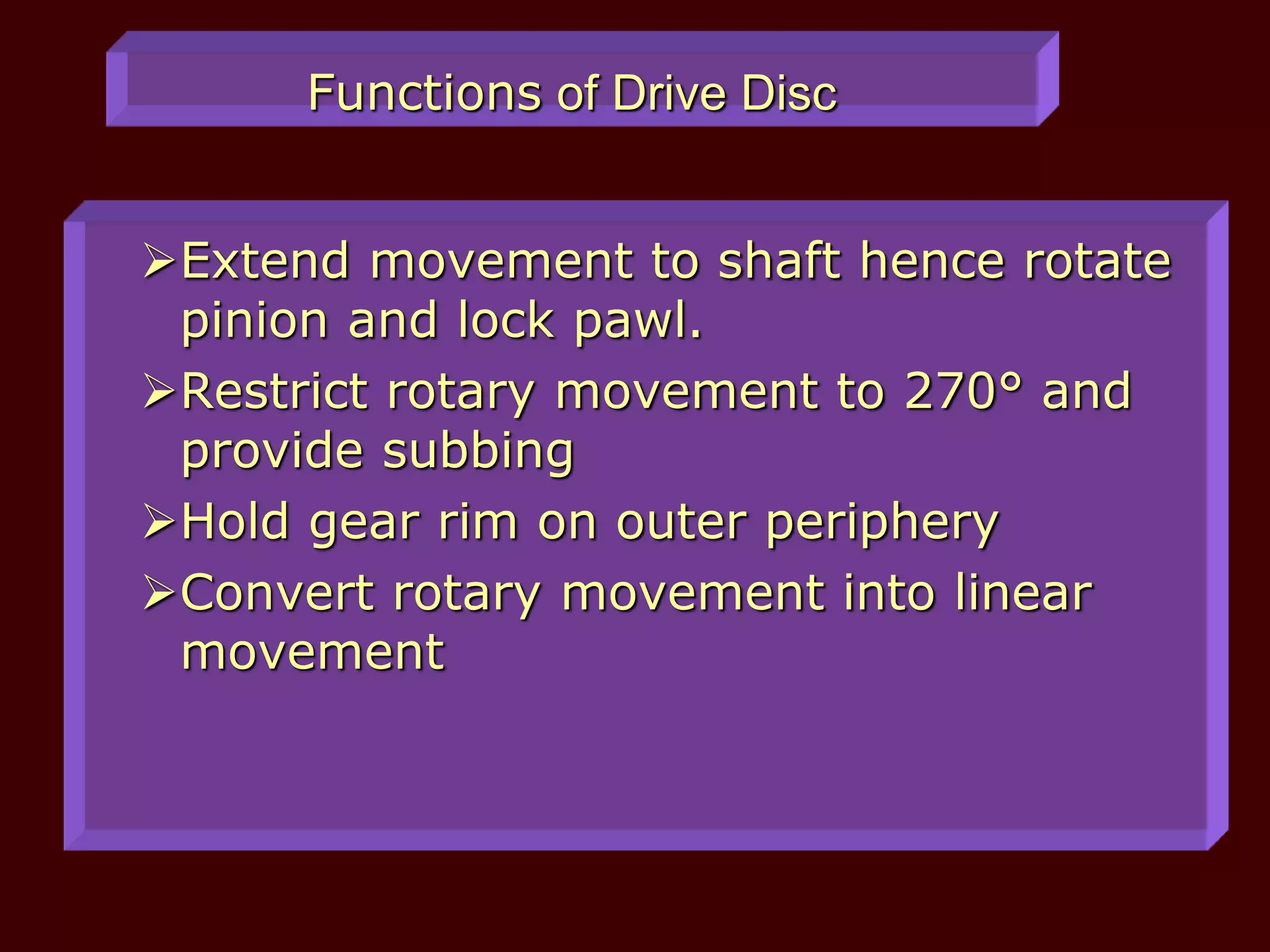
Functions of DriveDisc
Extend movement to shaft hence rotate
pinion and lock pawl.
Restrict rotary movement to 270° and
provide subbing
Hold gear rim on outer periphery
Convert rotary movement into linear
movement
50.
Gear rim &spring loaded slip rim
It is main part of friction
clutch where
rotary movement of motor
is extended to other parts
of machine
Overload protection to
motor achieved
Snubbing is achieved
The main parts are
Gear rim
Slip rim
Shoe expansion with
helical spring
51.
GEAR RIM &SPRING LOADED SLIP RIM
Shoe expansion
Helical spring
gear rim
slip rim
52.
Gear Rim
A circulargear having 92
teeth on it’s outer
periphery
It engages with pinion (12
teeth) of the Motor
It Accommodate slip rim
and spring loaded shoe
expansion.
When rotated by motor It
transmits rotary motion to
shoe expansion through
slip rim
53.
Slip rim
It issemicircular rim with
grips on it’s outer surface.
It’s width is less than the
width of gear rim
Rotate freely within gear
rim when not loaded by
spring.
When spring loaded it
rotate with gear rim
54.
Shoe expansion (lockingplate right & left) and helical spring
Two rectangular steel
strips hold by a clamp at
one end.
Other end butted against
slip rim ends.
Shoe expansion extends
rotary movement of gear
rim to lift out & drive disc.
Helical spring placed
between shoe expansion in
compressed condition.
Compressed spring compel
gear rim and slip rim to act
as one piece
55.
Sequence of rotationof gear &disc
How different gear and disc rotate in side friction
clutch
Pinion of motor rotates
Gear rim, then Gear rim rotates
slip rim then slip rim rotates
shoe expansion, then shoe rotates
lift out disc and
drive disc, then d.disc rotate
control disc and
shaft with pinion
& lock pawl
56.
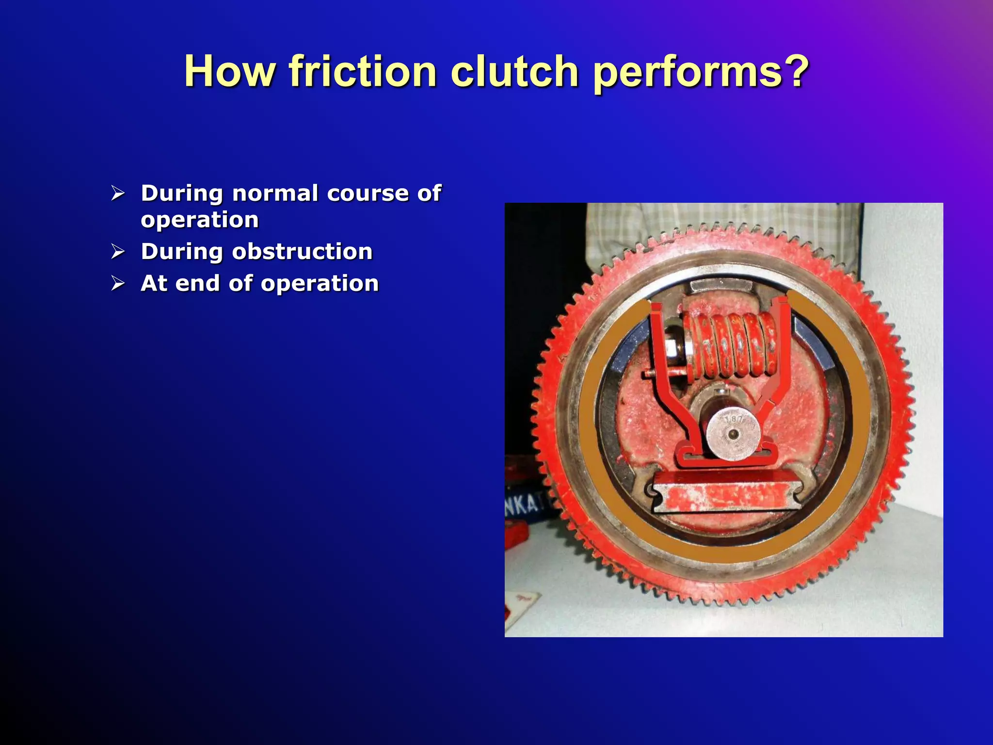
How friction clutchperforms?
During normal course of
operation
During obstruction
At end of operation
57.
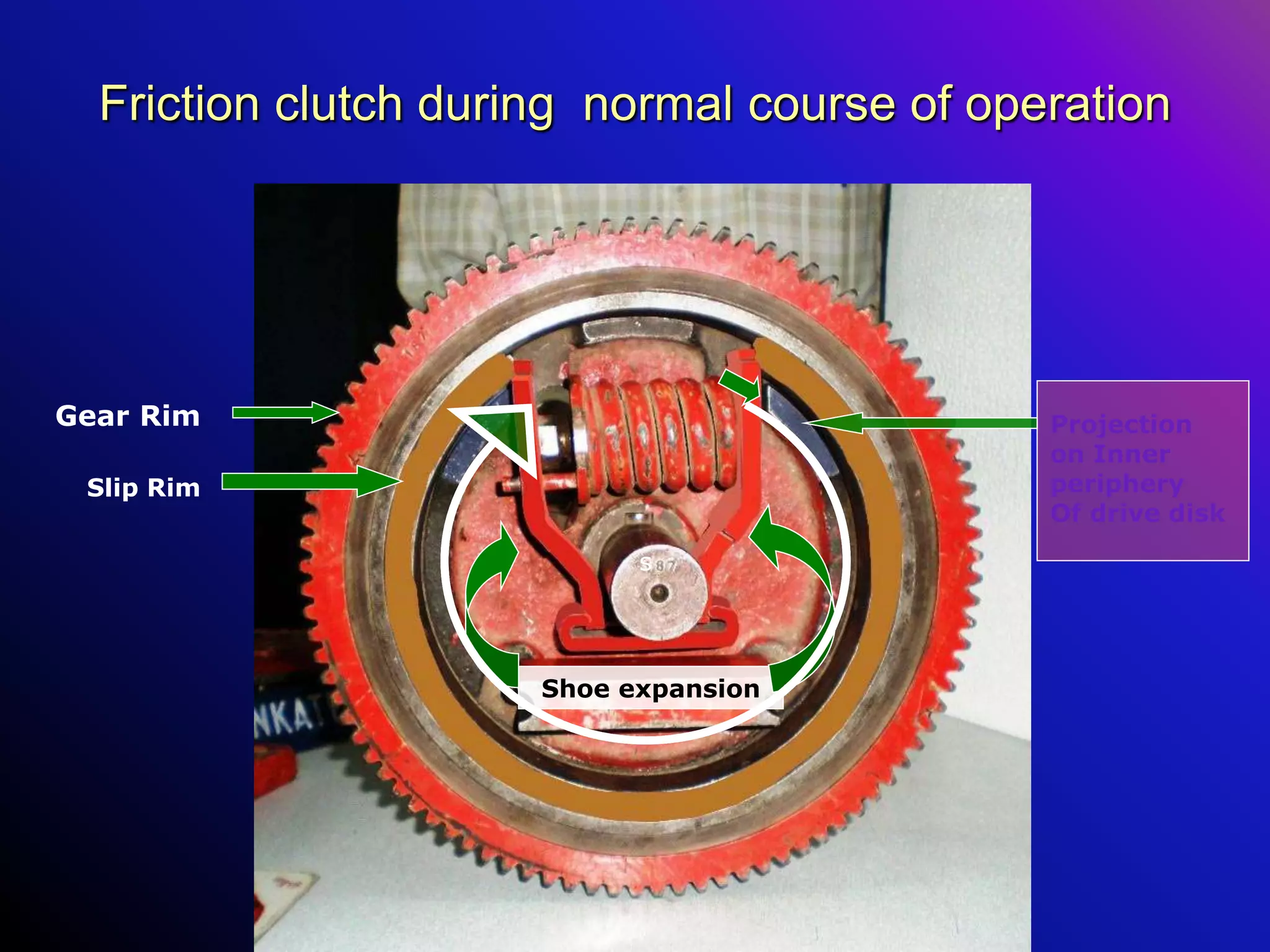
Friction clutch duringnormal course of operation
During normal course of operation
Pinion operates gear rim
slip rim & shoe expansion rotates along with gear rim as
these are spring loaded in side gear rim
the edge of one shoe expansion engages in the notch on
inner periphery of lift out disc & lift out disc rotates
the same edge of one shoe expansion engages with
projection on drive disc also & drive disc rotates
shaft rotates along with drive disc & stroke of 143mm
generated
Drive disc rotates control disc with the help of non-traleble
block.
58.
Friction clutch duringnormal course of operation
Gear Rim
Slip Rim
Projection
on Inner
periphery
Of drive disk
Shoe expansion
s
59.
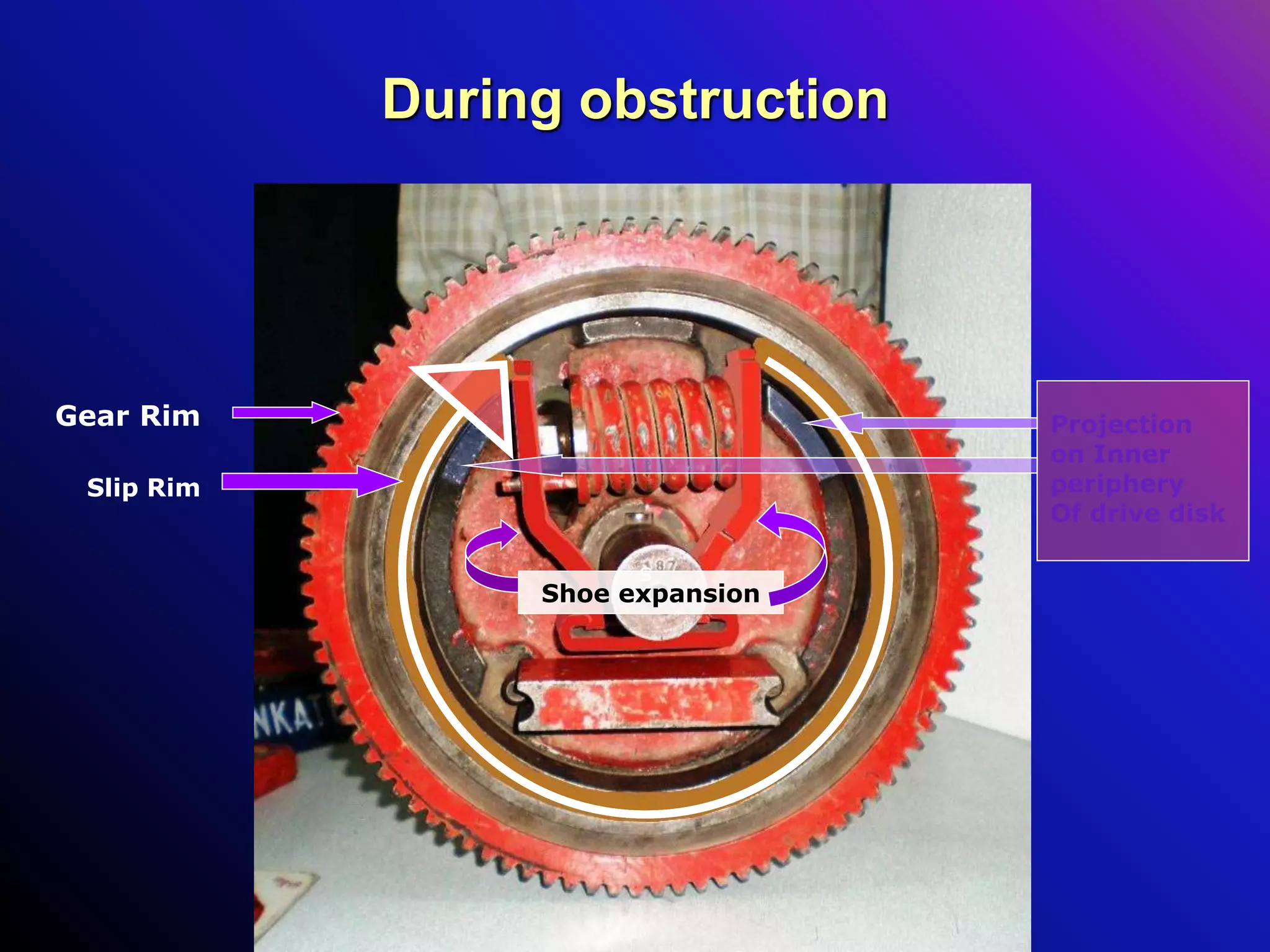
During obstruction
The drivedisc cannot rotate, as throw bar/gear rack is
stationary
Hence shoe expansion engages with projection on drive
disc also cannot rotate.
But pinion of motor forced to rotate gear rim
Hence rotary force will appear on other shoe expansion
The helical spring get compressed & slip rim collapse to
reduce circumference of slip rim
The gear rim alone rotates with slight friction between
gear rim& slip rim.
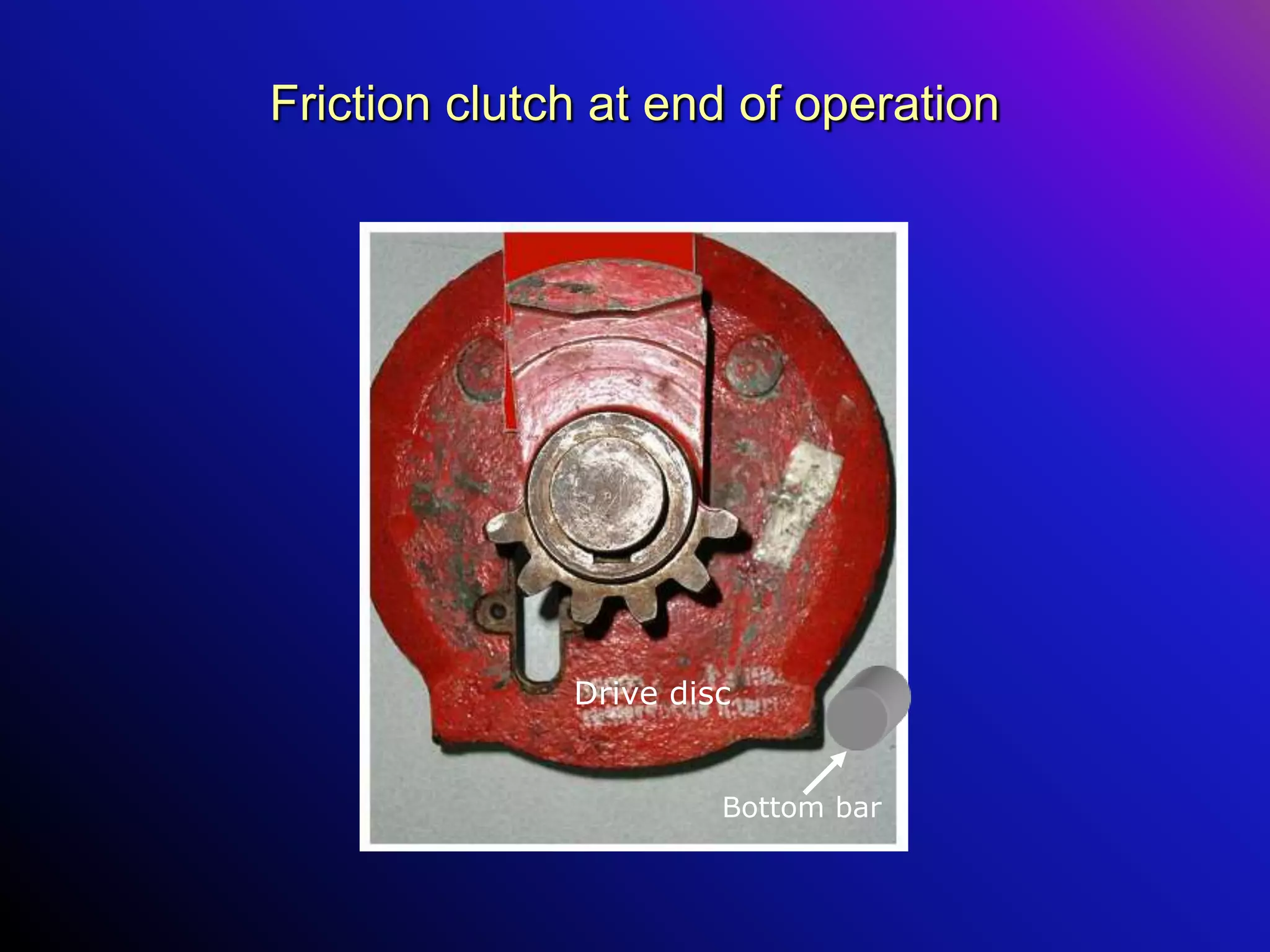
Friction clutch atend of operation
At end of operation projection on outer periphery of the
drive disc buts with bottom rod
Obstruction is generated inside the machine
Friction clutch slips & snubbing is achieved.
CONTACT ASSEMBLY WITHSPRING LOADED ROLLERS
Contact assembly
comprises of two spring
loaded contact groups
which are fixed inside
the casting.
Function of the contact
assembly: - make and
break the sets of
contact.
One group Contains two
sets of contact fixed
side by side
Contact controls feed
(Power) to motor and
point indication relay
65.
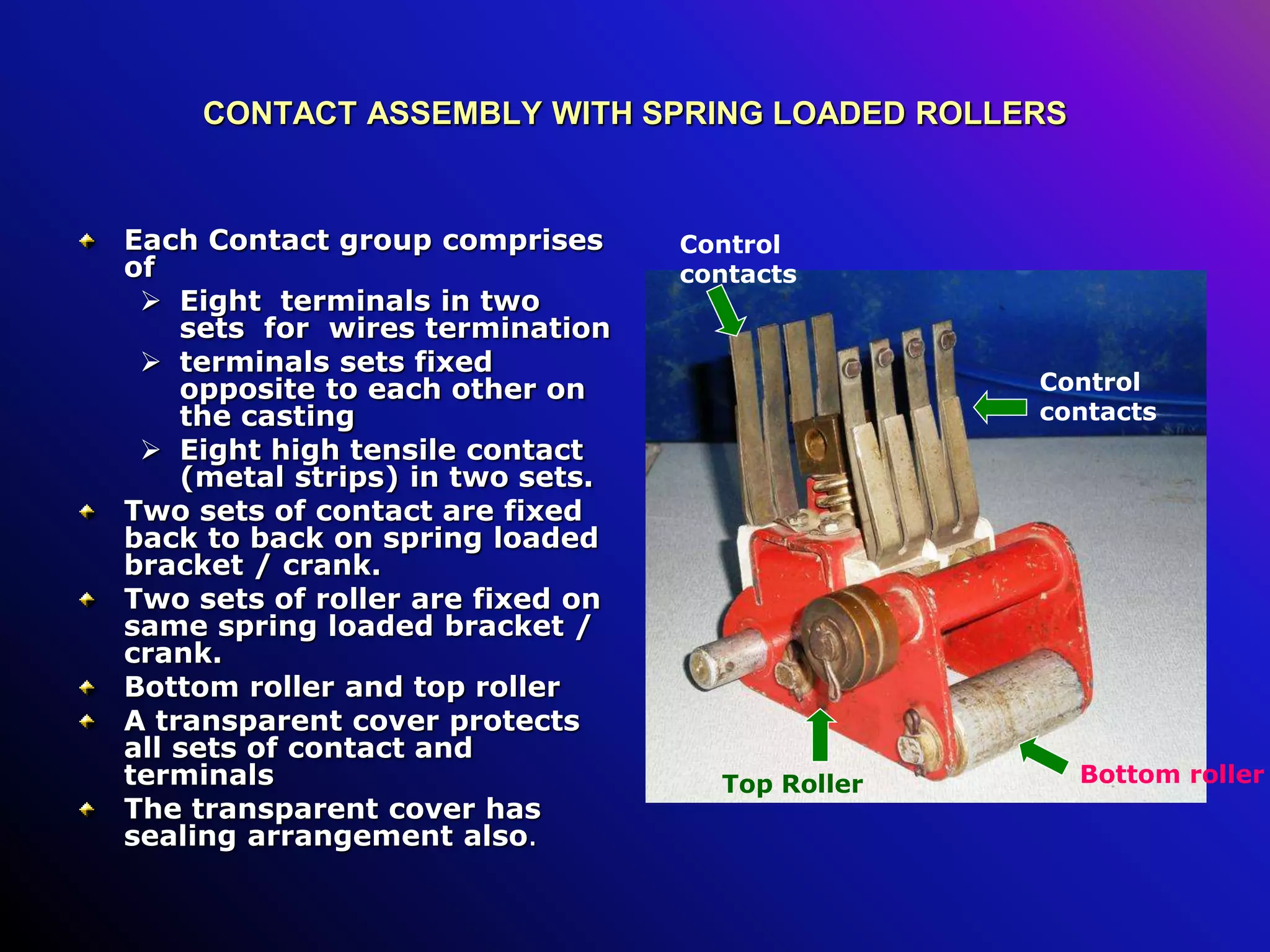
CONTACT ASSEMBLY WITHSPRING LOADED ROLLERS
Each Contact group comprises
of
Eight terminals in two
sets for wires termination
terminals sets fixed
opposite to each other on
the casting
Eight high tensile contact
(metal strips) in two sets.
Two sets of contact are fixed
back to back on spring loaded
bracket / crank.
Two sets of roller are fixed on
same spring loaded bracket /
crank.
Bottom roller and top roller
A transparent cover protects
all sets of contact and
terminals
The transparent cover has
sealing arrangement also.
Bottom roller
Top Roller
Control
contacts
Control
contacts
66.
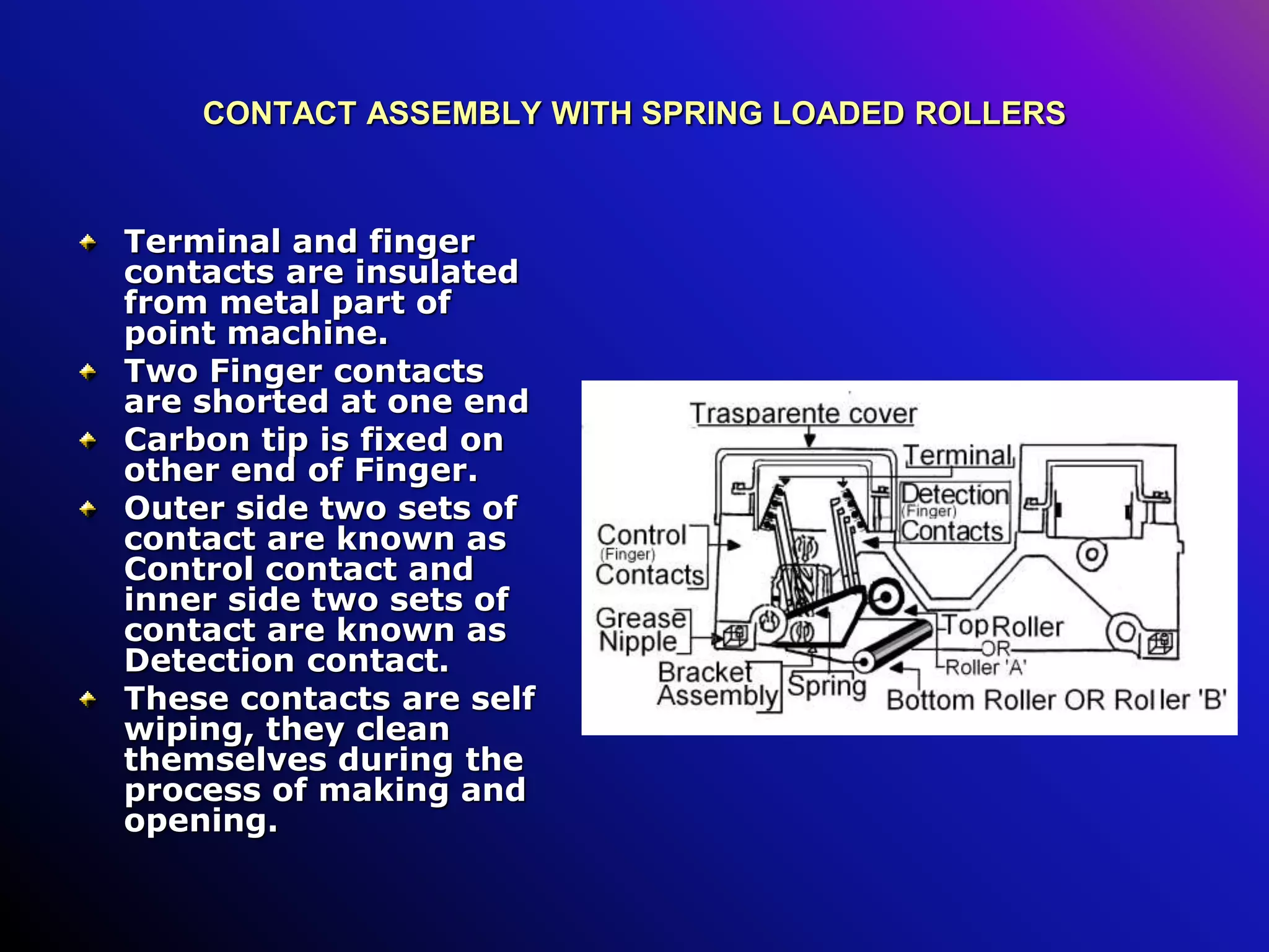
CONTACT ASSEMBLY WITHSPRING LOADED ROLLERS
Terminal and finger
contacts are insulated
from metal part of
point machine.
Two Finger contacts
are shorted at one end
Carbon tip is fixed on
other end of Finger.
Outer side two sets of
contact are known as
Control contact and
inner side two sets of
contact are known as
Detection contact.
These contacts are self
wiping, they clean
themselves during the
process of making and
opening.
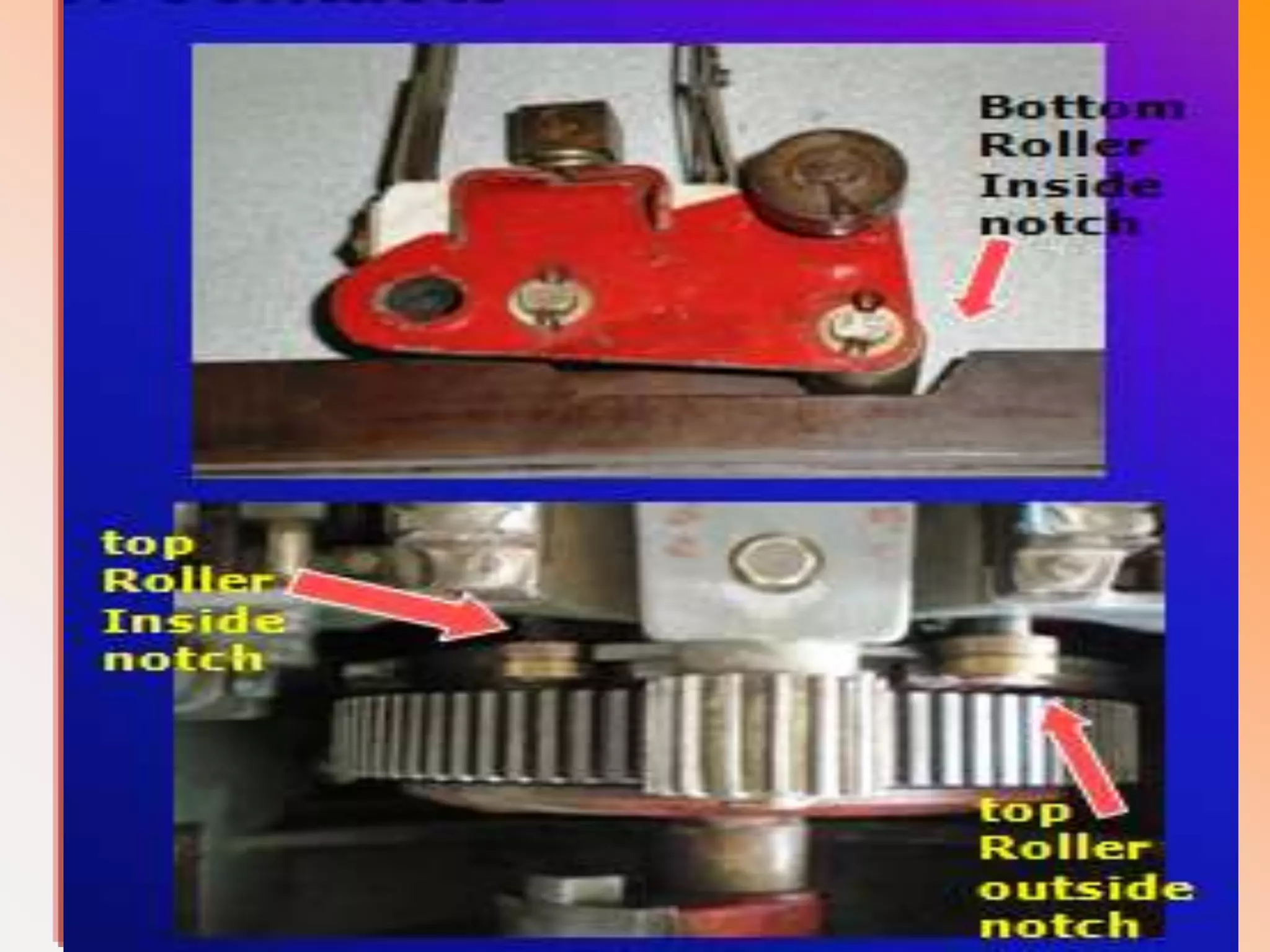
Making of contacts
Makingof contact depend
upon position of top and
bottom roller on the
periphery of control disc and
detection slide respectively.
Detection contact in one
group & control contact in
other group makes when
top roller fall in nominated
notch on friction clutch
bottom roller fall in
nominated notch on
periphery detection slide.
Falling of top roller in notch
proves correct locking of
point
Falling of bottom roller in
notch proves correct setting
of switches / points.
Bottom
Roller
Inside
notch
top
Roller
Inside
notch
top
Roller
outside
notch
69.
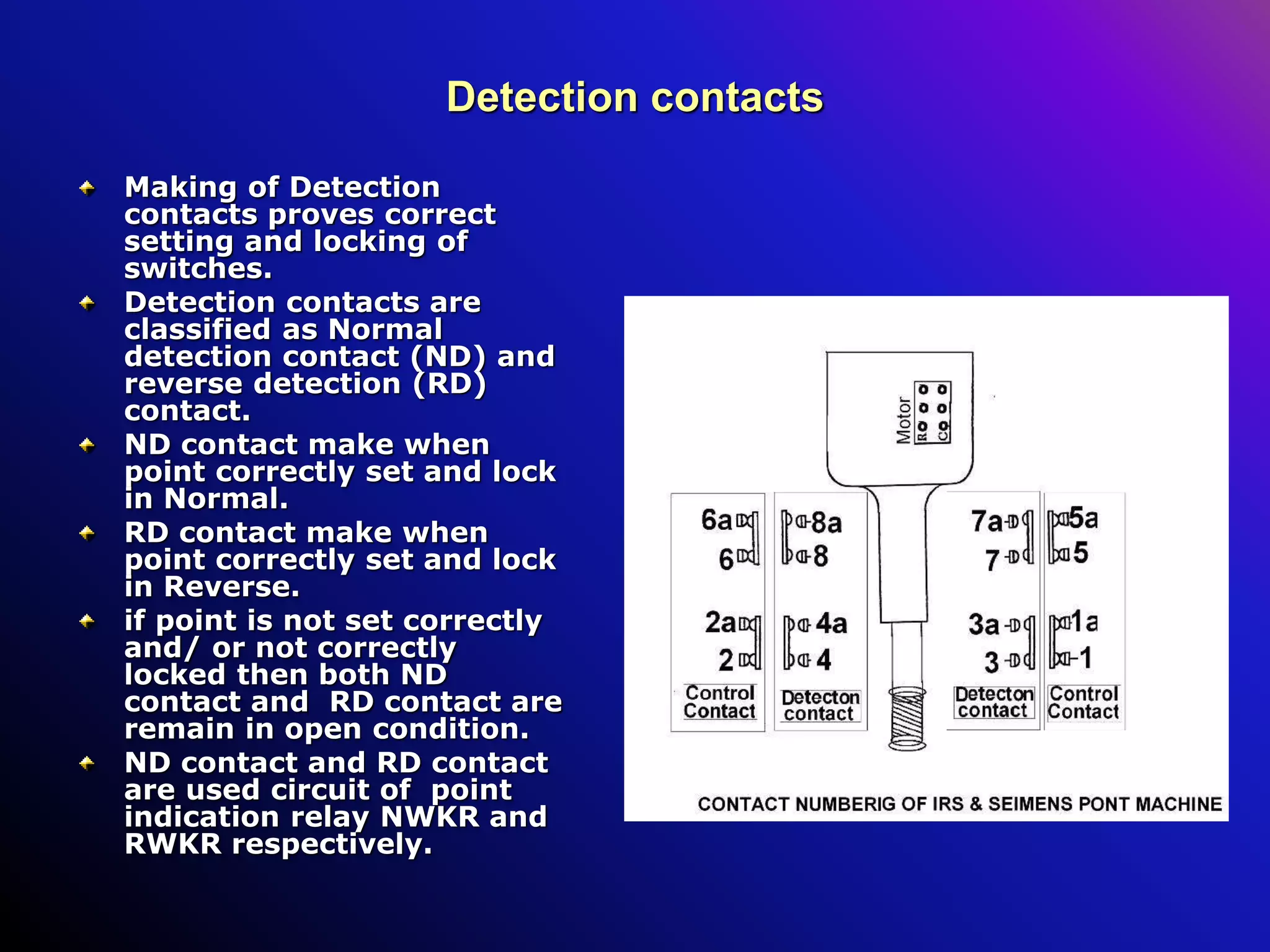
Detection contacts
Making ofDetection
contacts proves correct
setting and locking of
switches.
Detection contacts are
classified as Normal
detection contact (ND) and
reverse detection (RD)
contact.
ND contact make when
point correctly set and lock
in Normal.
RD contact make when
point correctly set and lock
in Reverse.
if point is not set correctly
and/ or not correctly
locked then both ND
contact and RD contact are
remain in open condition.
ND contact and RD contact
are used circuit of point
indication relay NWKR and
RWKR respectively.
70.
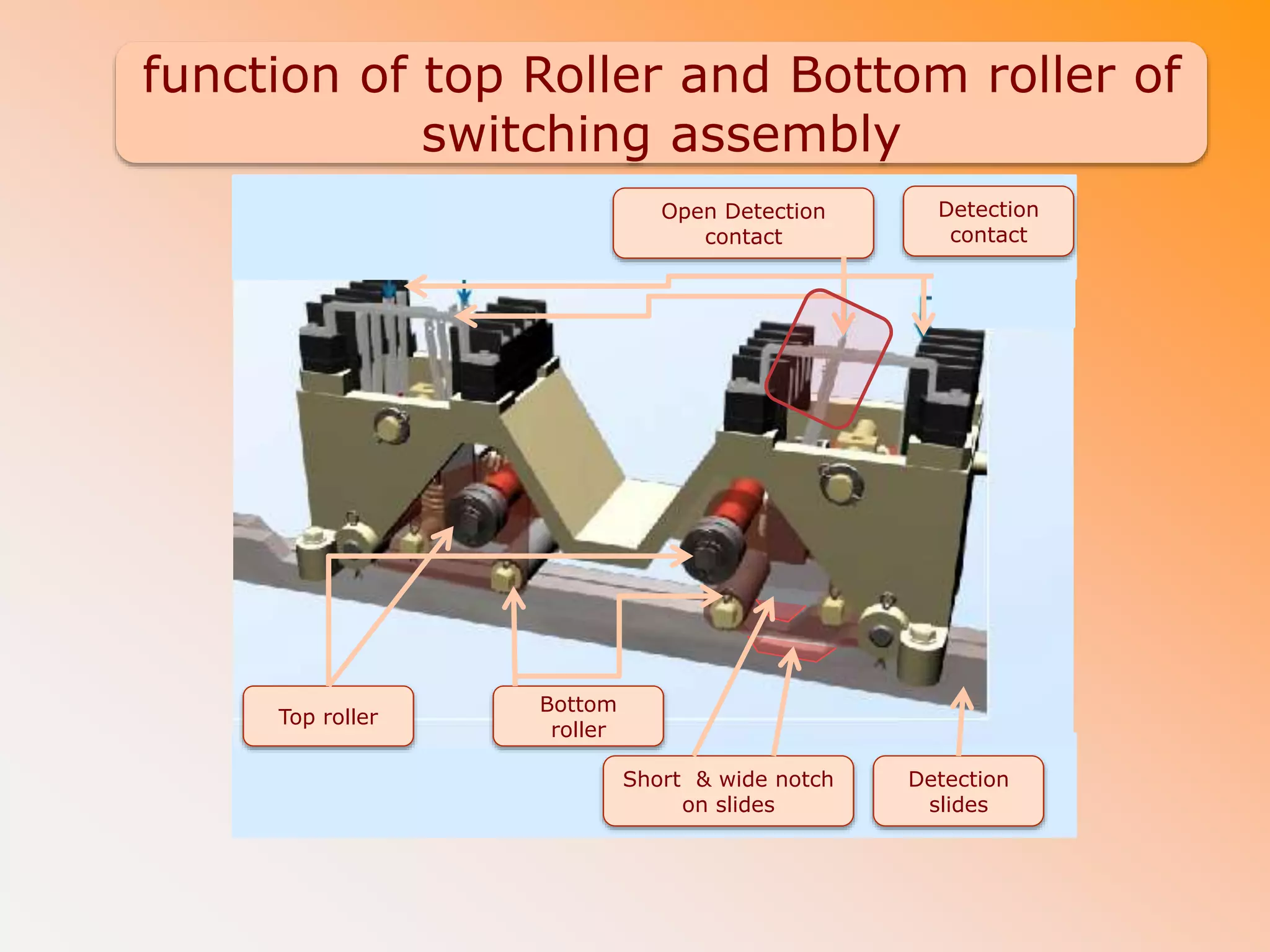
Check for Correctsetting and locking of point
The notches on detection slides and friction
clutch can be make available for bottom and top
roller by moving lock slides and detection slides.
Dose it Mean that ND & RD contacts can make
even though point is not lock and set?
proving of correct setting and locking of point
by ND & RD contact is subject to condition that
length of ground connections between point
slides are accurately adjusted.
This is prime check to be done at site during
installation & Maintenance
71.
Control contact
Feed tomotor is control through these contacts
Control contact controls feed to motor in normal course of
working Types of Control contacts
Normal Control contact (NC)
Reverse Control contact (RC).
When points set and lock in Normal then RC contact makes.
When points set and lock in Reverse then NC contact
makes.
When point is not correctly set and/ or not correctly locked
position than both NC contact &RC contact are remain in
make condition.
NC contact controls feed for reveres to normal operation of
point
RC contact controls feed for normal to reveres operation of
point.
NC or RC opens as soon as point correctly set and lock in
required position.
Detection slides
D Typedetection slid
C Type Detection slid
Wide notch
Small notch Threaded Stud
Brass stripe
74.
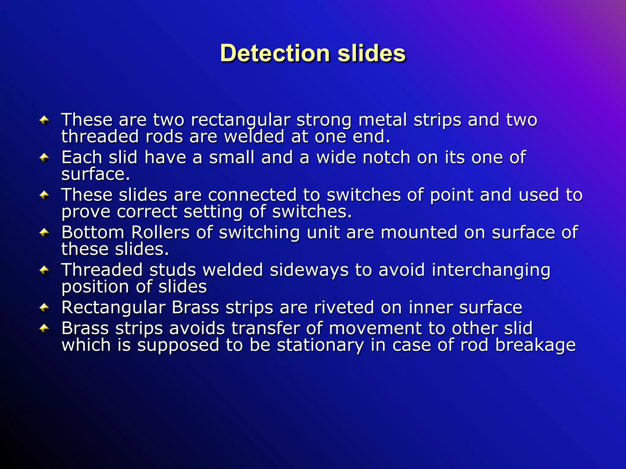
Detection slides
These aretwo rectangular strong metal strips and two
threaded rods are welded at one end.
Each slid have a small and a wide notch on its one of
surface.
These slides are connected to switches of point and used to
prove correct setting of switches.
Bottom Rollers of switching unit are mounted on surface of
these slides.
Threaded studs welded sideways to avoid interchanging
position of slides
Rectangular Brass strips are riveted on inner surface
Brass strips avoids transfer of movement to other slid
which is supposed to be stationary in case of rod breakage
75.
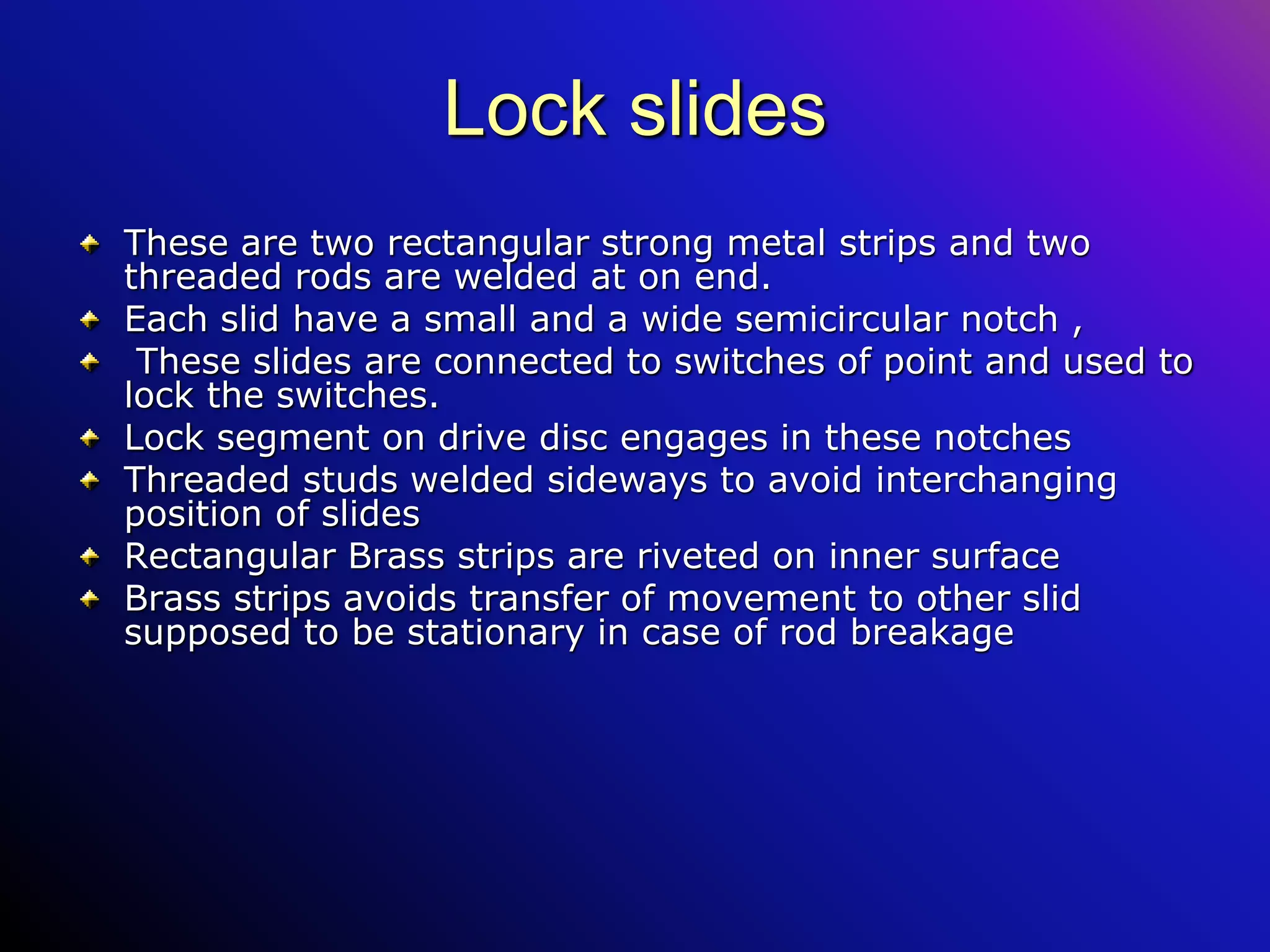
Lock slides
These aretwo rectangular strong metal strips and two
threaded rods are welded at on end.
Each slid have a small and a wide semicircular notch ,
These slides are connected to switches of point and used to
lock the switches.
Lock segment on drive disc engages in these notches
Threaded studs welded sideways to avoid interchanging
position of slides
Rectangular Brass strips are riveted on inner surface
Brass strips avoids transfer of movement to other slid
supposed to be stationary in case of rod breakage
76.
mainteance sechdule
Sr.
No
Maintenance workto be done
Periodi
city
1 Check the machines are kept free from rust, dirt and fixtures. Check for tightness
2 Check lubrication of all gears and bearings
3 Check that machine is not slips from its place at starting and at end of operation
4 Check that both carbon brushes are resting on commutator with sufficient pressure
5 Check the proper ballasting and packing of sleepers
6 Tighten all nuts, check nuts & bolts. Tighten lock nuts holding the detector slides and lock slides with
lugs are kept tight. After tightening the nut and lock nut should be turned in opposite direction
towards each other to lock the nut
7 Track locking test is to be done, during every inspection
8 Gauge tie plate provided for motor point is properly fixed
9 Ensure all the bridge contacts make and break at the same time
10 At least 5 to 7 sleepers from SRJ chair plates should be in full tight condition.
11 All pins of ‘p’ bracket or ‘d’ bracket are of the standard type only,and there should not be any play.
12 Check the functioning of overload arrangement and out of correspondence
13 Gauge test is to be done during every inspection.
14 Check all grease nipples provided are in position Recommended type grease should be used
15 Check the setting of switches for having required amount of spring action.
16 Measure the voltage & current at motor terminals for both normal& reverse operations. These should
be within the specified limits according to the different types of point machines.
77.
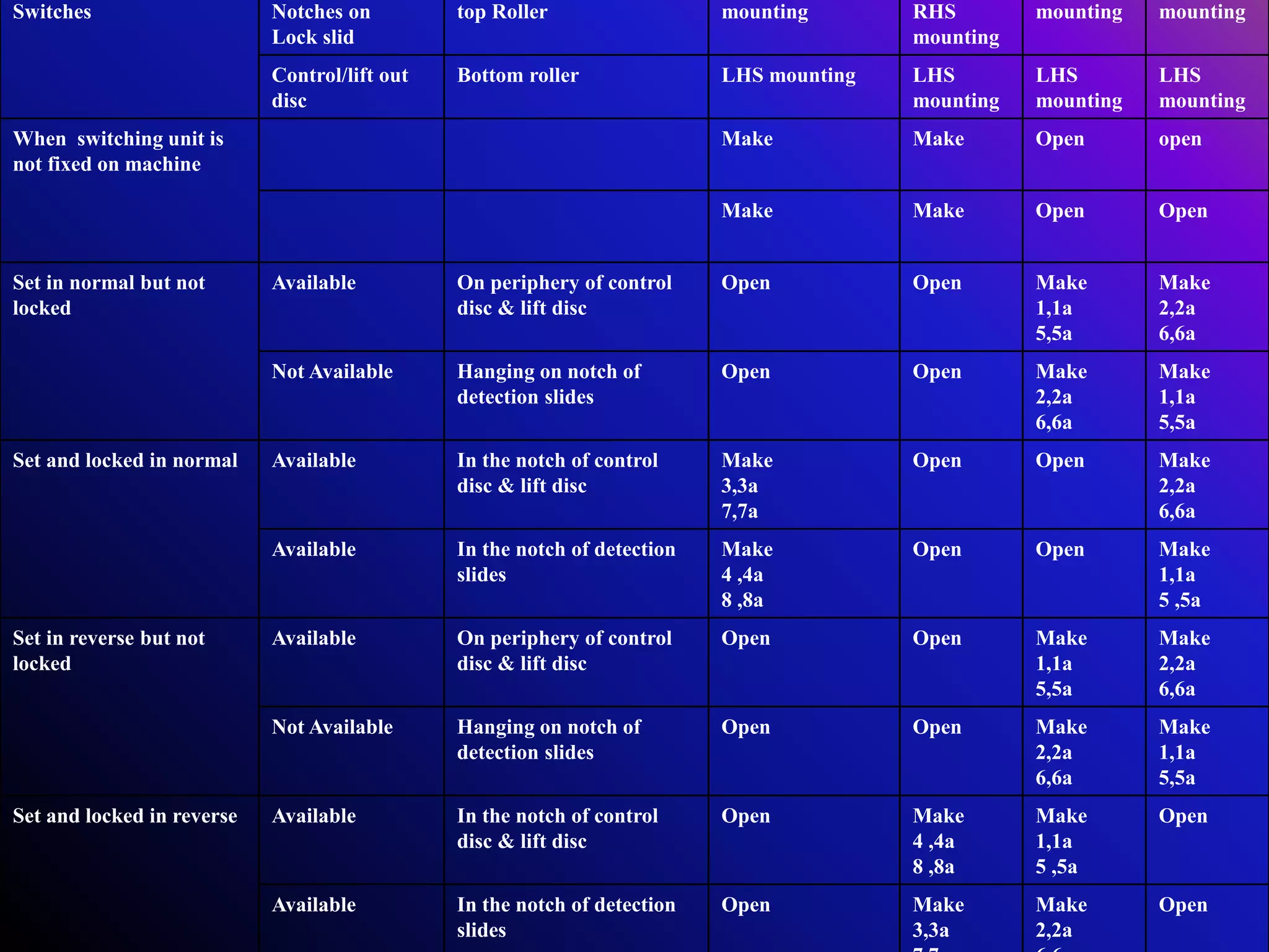
Switches Notches on
Lockslid
top Roller mounting RHS
mounting
mounting mounting
Control/lift out
disc
Bottom roller LHS mounting LHS
mounting
LHS
mounting
LHS
mounting
When switching unit is
not fixed on machine
Make Make Open open
Make Make Open Open
Set in normal but not
locked
Available On periphery of control
disc & lift disc
Open Open Make
1,1a
5,5a
Make
2,2a
6,6a
Not Available Hanging on notch of
detection slides
Open Open Make
2,2a
6,6a
Make
1,1a
5,5a
Set and locked in normal Available In the notch of control
disc & lift disc
Make
3,3a
7,7a
Open Open Make
2,2a
6,6a
Available In the notch of detection
slides
Make
4 ,4a
8 ,8a
Open Open Make
1,1a
5 ,5a
Set in reverse but not
locked
Available On periphery of control
disc & lift disc
Open Open Make
1,1a
5,5a
Make
2,2a
6,6a
Not Available Hanging on notch of
detection slides
Open Open Make
2,2a
6,6a
Make
1,1a
5,5a
Set and locked in reverse Available In the notch of control
disc & lift disc
Open Make
4 ,4a
8 ,8a
Make
1,1a
5 ,5a
Open
Available In the notch of detection
slides
Open Make
3,3a
Make
2,2a
Open
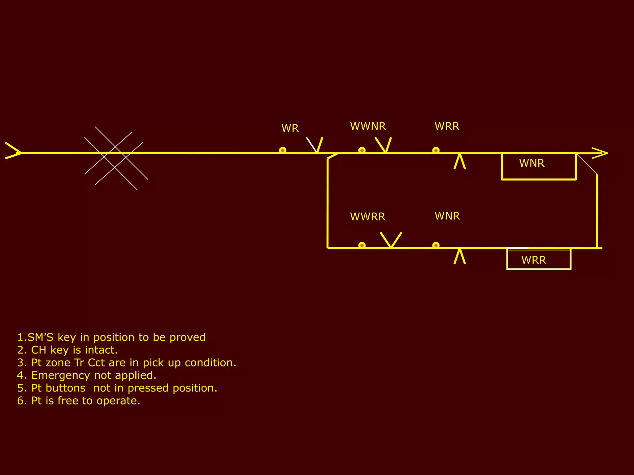
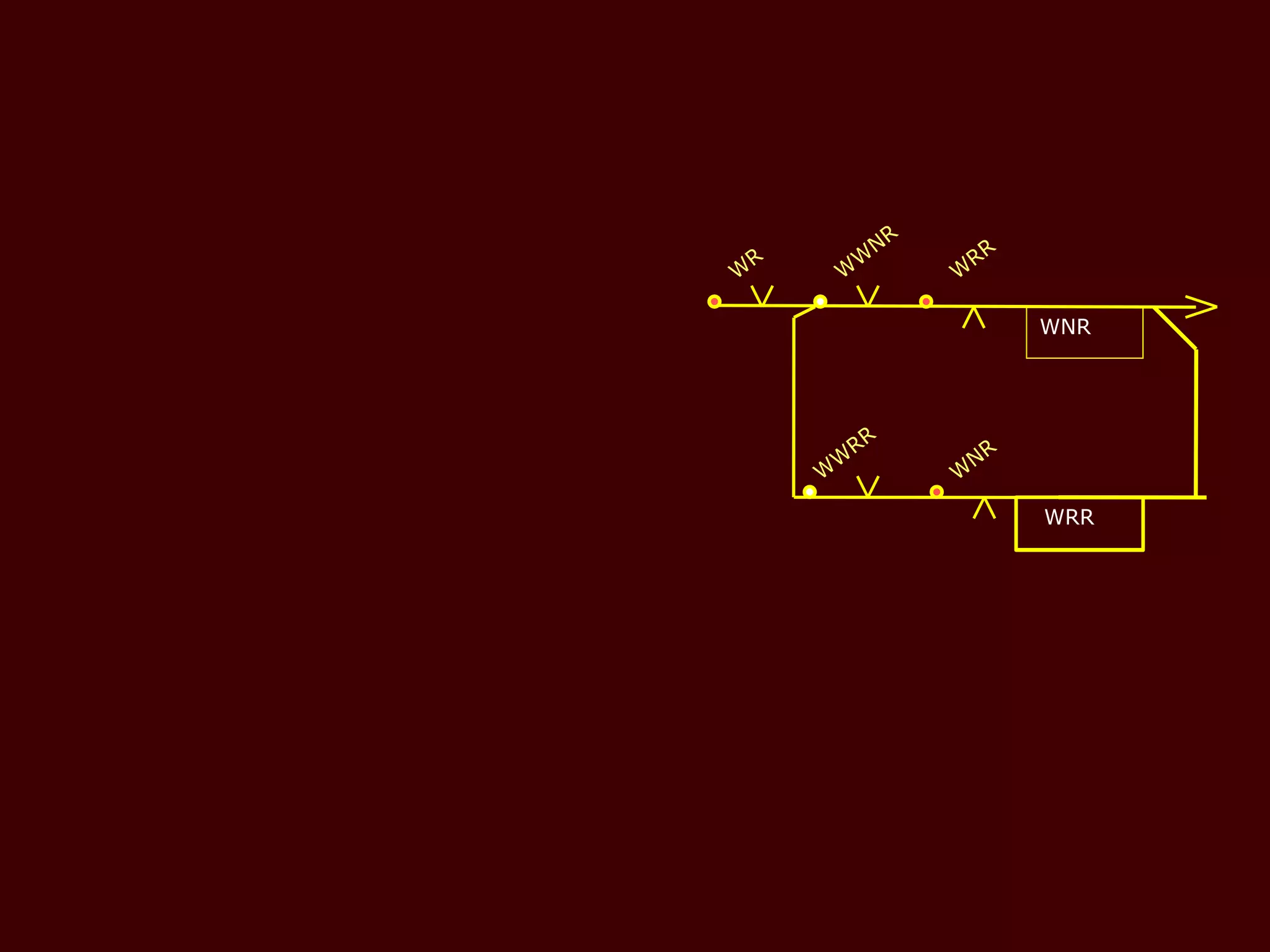
WNR
WRR
WWNR WRR
WWRR WNR
1.SM’Skey in position to be proved
2. CH key is intact.
3. Pt zone Tr Cct are in pick up condition.
4. Emergency not applied.
5. Pt buttons not in pressed position.
6. Pt is free to operate.
WR