Hammond d v dt load filter
•
0 likes•160 views
How a dV/dT Filter on the Load Side of a VFD can: 1. Reduce motor audible noise 2. Reduce motor motor heating and lower efficiencies 3. Reduce motor winding and bearing damage with long lead lengths
Report
Share
Report
Share
Download to read offline

Recommended
Bernard Gittins NSW Trade & Investment Mine Safety - If it's not "on" It's no...
Bernard Gittins NSW Trade & Investment Mine Safety - If it's not "on" It's no...NSW Environment and Planning
This document discusses potential issues with electrical protection on systems using variable speed drives (VSDs) with non-sinusoidal voltage outputs. It notes that traditional mining relay systems and protections may not fully ensure safety in all situations with VSDs. Wideband earth leakage units can detect faults and currents but cannot manage all risks. Circulating capacitive currents between VSD components even without faults could theoretically cause fires. Existing protection settings may need to be reconsidered to safely operate VSD systems, and alternative VSD designs that minimize stray currents are recommended.SHERLOCK
This document analyzes the effects of variations in aggressor line loads on victim interconnect lines in VLSI systems. It studies how signal delay, power dissipation, and crosstalk noise are impacted. Various techniques for mitigating these non-ideal effects are explored, including repeater insertion, shielding, and skewing. Simulation results show that shielding and skewing together most effectively reduce delay and power compared to other approaches. The document concludes that non-ideal effects depend strongly on load types and input signals, and can be minimized through the application of these techniques.
Notes1 intro
The document discusses the key components of power distribution systems, focusing on distribution substations, the primary distribution system, and secondary distribution. It notes that distribution systems receive power from transmission systems and supply power to customers at lower voltages. The main components include distribution substations for voltage transformation and switching/protection, primary feeders that distribute power radially or in loops, and secondary laterals that supply individual customers.
VARIABLES-FREQUENCY DRIVES <VFD>
PWM type VFDs are an improved version of VSI type variable frequency drives that use pulse width modulation. The document explains that PWM VFDs use a diode bridge to rectify AC to DC, and a switching circuit controls the duty cycle to provide a stable variable frequency voltage output to the load. An additional regulator is used to regulate the PWM output and provide stable voltage and current.
Busbar Blocking System
This document discusses busbar blocking systems for power system protection. It explains that while busbars were often left unprotected in the past due to reliability and coordination challenges, busbar blocking technology can now provide fast and selective protection. The document outlines the requirements, types of protection, and operation of busbar blocking schemes. It provides examples of how busbar blocking is applied using overcurrent relays and communications between relays to block tripping during feeder faults but allow fast tripping for busbar faults. Busbar blocking provides benefits like faster fault clearing and minimal additional cost compared to relying on upstream feeder protection alone.
7SR23 High Impedance Bus Bar Protection Relay
The 7SR23 DAD is a numeric high impedance circulating current relay has four current inputs, it is used as a unit protection to detect phase and earth faults.
The relay can be applied to busbars, connections, transformers, reactors and motors.
Twt pulse amplifiers
This document provides information on various microwave amplifier products offered by Jyoti Electronics, including:
1) Pulse TWT amplifiers from 1-50kW with frequencies up to 35.5GHz and pulse widths from 0.1-1500us.
2) CW TWT amplifiers that can provide frequencies from 4-47GHz with 500 watts of continuous wave power.
3) Dual mode TWT amplifiers that can operate in both pulse and CW modes with powers up to 150W, frequencies from 18-26.5GHz or 25.5-40GHz, and pulse widths from 0.07-continuous wave.
4) Magnetron transmitters with continuously variable
4 Sed2 Harmonics Overview
1) Harmonics are voltages or currents that are integer multiples of the fundamental power line frequency, and they are caused by non-linear loads that distort the sine wave.
2) Harmonic currents flow at frequencies that are multiples of the fundamental frequency, adding in a distorted way to the current waveform.
3) Harmonics can interfere with equipment, require oversizing of electrical systems, and reduce the load carrying capacity of power systems.
Bridged car amplifier
The document discusses Bridged car Amplifiers, which are high impedance amplifiers used for intracellular recordings with sharp microelectrodes. Each amplifier is housed in a 19" rackmount cabinet with features like gain and offset controls. The Bridged car Amplifier -01x model has an expanded current range, making it suitable for electroporation of single cells. Key specifications of the amplifier headstage and controls are provided. The amplifier allows both intracellular and extracellular recordings and comes with a standard headstage and connectors.
General electric
1. Microprocessor-based current differential relays can provide superior protection for transmission lines but applying them to lines with tapped transformers presents challenges. Currents are not measured at tap points.
2. Key issues are the load current from taps appearing as a differential error, faults at the low voltage side of taps misleading the relay, and magnetizing inrush current. Distance elements and removing zero-sequence current can help address these issues.
3. Solutions proposed in the document include using biased characteristics, adaptive compensation for charging currents, distance supervision set to avoid taps, and removing zero-sequence current from the differential signal. Careful setting is needed to balance security and sensitivity.
An adaptive zvs full bridge dc–dc converter with reduced conduction losses an...
An adaptive zvs full bridge dc–dc converter with reduced conduction losses and frequency variation range
To Get this projects Call : 9566355386 / 99625 88976
Visit : www.lemenizinfotech.com / www.ieeemaster.com
Mail : projects@lemenizinfotech.com
Hvdc ppt with animated videos
HVDC transmission systems allow for long distance and submarine power transmission with lower transmission losses compared to HVAC. HVDC uses converter stations to convert AC to DC for transmission and back to AC at the receiving end. Some key advantages are long distance transmission over 500km is more economical with HVDC, lower line losses, and ability to interconnect AC grids of different frequencies. HVDC is increasingly being used to integrate renewable energy sources like offshore wind farms.
UNIT - 05 DISTRIBUTION LINES AND TRANSFORMER CENTRE
Code of practice for Distribution Lines and Transformer centre, types of transformer centres -
Pole mounted, plinth mounted, indoor and outdoor types. Determining the rating of
Distribution Transformer. Write Specifications of the Distribution Transformer. Draw the
SLD of a Transformer centre indicating the size of protective devices, Prepare the schedule of
equipments /Materials with specifications for a 11KV/415V,100 KVA transformer centre and
their estimates, 415 V LT line materials and specifications , method of calculating various LT
line materials (only). Prepare the schedule of materials (only) for 3 phase 4 wire LT line,
11 KV HT Line-materials and their specifications, method of calculating various HT line
materials and tapping structure, TOPO sheet and its use, Concept of combined estimates.
Prepare the schedule of materials (only) for 11 KV single circuit HT line for Rural
Electrification.
(Note: HT lines over head type only)
220kv GSS, VKIA, jaipur
This document summarizes a seminar on practical training at a 220kV grid substation. It describes the various components of the substation including lightning arrestors, capacitive voltage transformers, wave traps, isolators, current transformers, circuit breakers, bus bars, transformers, protective relays, and the control room. The conclusion states that the training provided insight into the real instruments used at the substation and how it operates to manage transmission of electricity.
Presentation basic
This presentation summarizes different types of clipper circuits. It defines clippers as circuits that can clip off or remove unwanted portions of an input waveform without distorting the rest. The presentation describes series and parallel/shunt clipper circuits, and provides examples of unbiased and biased series and parallel clipper circuits. It explains how different clipper circuits work and lists some applications of clippers such as changing waveform shapes and circuit transient protection.
Hvdc transmission (by arsalan ali)
i've made this presentation for my purposes bt if it can help out someone else too then i'll b happy more than for myself. i think these slides help you a lot to understand the concepts of HVDC transmission.And may be you like the way i present it.....
TDU - Unit 02 - HVDC, FACTS and sub-stations
The document discusses HVDC transmission systems and FACTS. It provides details on the components and operation of HVDC systems, including converter stations, filters, transformers, transmission lines, and switchgear. HVDC is described as using DC for long distance, bulk power transmission between asynchronous AC networks, with advantages over HVAC like reduced costs and losses. FACTS are defined as using power electronics to improve transmission system controllability, stability, and power transfer capability. The key objectives and benefits of FACTS are also summarized.
Lect2 up080 (100324)
This document discusses latchup and electrostatic discharge (ESD) in CMOS integrated circuits. It begins by defining latchup as the creation of a low impedance path between power supply rails, which is caused by triggering parasitic bipolar transistors within the circuit. It then discusses how latchup occurs via the regenerative process in a parasitic pnpn structure, and how it can be triggered by current or voltage. The document provides guidelines for preventing latchup through techniques like guard rings and layout optimizations. It also defines ESD as the discharge of static electricity and discusses how it can damage integrated circuits if the built-up charge is not properly dissipated.
PPt on 220 kV substation
This document summarizes a 220kV substation in Kanpur, India. It has three main sections: a panel section containing control panels and relay panels, a switchyard containing components like circuit breakers and transformers, and a battery room. The substation receives 220kV power from two incoming lines and steps it down to 132kV and 33kV for outgoing distribution lines. It uses transformers to convert between voltages and buses to distribute power. Key terms like tripping, shutdown, and breakdown are also defined relating to power disruptions and maintenance.
SEBA KMT MFM5 1 Cable Sheath Testing, Fault Prelocation & Pinpointing
SEBA KMT MFM5-1 is the universal test instrument for cable sheath testing including prelocation and pinpointing of cable sheath faults - in sheath testing mode SEBA KMT MFM5-1 can detect minute cable sheath insulation damage on low and high voltage cable networks.
SEBA KMT MFM5-1 ensures fast and precise cable sheath fault location - the instrument is menu-driven and fully automatic sheath fault prelocation is accurately achieved by inputting total cable length. SEBA KMT ESG 80-2 can be combined with the MFM5-1 for earth fault location in LV-HV cables.
Cable Sheath Test & Fault Location SEBA KMT MFM5-1 Features : Sheath testing, fault prelocation and pinpointing combined in single unit, sheath testing up to 5kV, time saving prelocation of sheath fault.
Instrument transformer __cvt_transformer
Siemens produces capacitor voltage transformers (CVTs) that convert high transmission voltages to standardized low voltages for metering, protection, and control purposes. The CVTs consist of series connected capacitor elements housed in porcelain shells that step down the voltage, with an electromagnetic circuit in an aluminum base box that provides the final output voltages. CVTs accurately transform voltages while also coupling high frequency power line carrier signals and suppressing ferroresonance to provide reliable performance over long periods of time.
220kv gss pindwara(sirohi)
This document summarizes a seminar presented on practical training at a 220kV substation. It includes an introduction to the substation and descriptions of its key components like transformers, circuit breakers, current transformers, lightning arrestors, capacitors and the control room. Diagrams of the substation's single line diagram are also included. The conclusion states that the training provided insight into real instrumentation used at substations and how they are operated and managed.
Latchup latchup
The document discusses latch-up in CMOS analog switches and how to prevent it. Latch-up occurs when a parasitic SCR structure forms a low-impedance path between power rails, allowing excessive current flow. It can be triggered by overvoltages, signals exceeding supply rails, or improper power sequencing. Prevention methods include adding diodes to limit voltages, ensuring supplies are applied properly, and using trench isolation processing to eliminate parasitic transistors and make devices latch-up proof.
Kollmorgen next step_microstepping_drive_specsheet
The document provides specifications for two NextStep microstepping drives, the NextStep and NextStep-240. The NextStep has step sizes ranging from 5000 to 50000 and can output currents from 0-7.9 amps in increments of 0.1 amps. The NextStep-240 has step sizes ranging from 5000 to 50000 and can output currents from 0-3.9 amps in increments of 0.1 amps. Both drives have protection from short circuits, under voltage, over temperature, interlocks, and over voltage. The NextStep has a package size of 137.16 x 137.16 x 63.5 mm.
Substation equipment and its function 2
The document discusses the functions and types of equipment used in electrical distribution substations. It provides descriptions of common substation equipment such as power transformers, circuit breakers, disconnecting switches, bus bars, current and potential transformers, capacitors, reactors, protective relays and batteries. It also provides examples of how to calculate primary and secondary currents in transformers of different ratings and briefly discusses some common bus schemes used in Pakistan.
Transient Suppressors
Transients can cause slow degradation, erratic operation, or catastrophic failure in electrical parts, insulation dielectrics, and electrical contacts used in switches and relays. The possible occurrence of transients must be considered in the overall electronic design. Required circuit performance and reliability must be assured both during and after the transient
Power quality improvement using dvr
Power quality issues like voltage sags have become more problematic with sensitive electronic devices, potentially causing financial losses. A dynamic voltage restorer (DVR) can be used to improve power quality by compensating for voltage sags and other faults. This work investigates using a DVR with a PI controller and PWM pulse generator implemented on a DSP chip to regulate voltage for linear and induction motor loads during faults like sags, single phase ground faults, and double phase ground faults. It also examines how a DVR can address the starting voltage dip issue for induction motors.
B 24
This document discusses HVDC Light technology for electric power transmission. HVDC Light uses voltage source converters based on IGBT technology, allowing for faster switching speeds than traditional HVDC. HVDC Light can transmit power up to 330MW over long distances using polymeric cables buried underground. Key advantages include reduced environmental and health impacts compared to overhead power lines, longer cable distances than AC lines, and lower maintenance costs. Applications include connecting offshore wind farms and expanding transmission capacity.
Variable Frequency Drives . Are they worth it?
VFDs (variable frequency drives) are often specified to control pump speed for various reasons, but they are not always the best or most energy efficient solution. Alternatives to consider include pressure/flow control valves, bypass valves, changing pump impeller size, using multiple pumps, or varying the pumped fluid properties/conditions. While VFDs can provide benefits in some cases, they also have downsides such as increased capital and operating costs, reduced motor lifespan, and lower combined motor/VFD efficiency compared to running a properly sized pump at its best efficiency point. Engineers should evaluate all options before specifying a VFD and ensure the electrical design considers potential issues from voltage harmonics and other factors.
Ijetr012032
ER Publication,
IJETR, IJMCTR,
Journals,
International Journals,
High Impact Journals,
Monthly Journal,
Good quality Journals,
Research,
Research Papers,
Research Article,
Free Journals, Open access Journals,
erpublication.org,
Engineering Journal,
Science Journals,
More Related Content
What's hot
Bridged car amplifier
The document discusses Bridged car Amplifiers, which are high impedance amplifiers used for intracellular recordings with sharp microelectrodes. Each amplifier is housed in a 19" rackmount cabinet with features like gain and offset controls. The Bridged car Amplifier -01x model has an expanded current range, making it suitable for electroporation of single cells. Key specifications of the amplifier headstage and controls are provided. The amplifier allows both intracellular and extracellular recordings and comes with a standard headstage and connectors.
General electric
1. Microprocessor-based current differential relays can provide superior protection for transmission lines but applying them to lines with tapped transformers presents challenges. Currents are not measured at tap points.
2. Key issues are the load current from taps appearing as a differential error, faults at the low voltage side of taps misleading the relay, and magnetizing inrush current. Distance elements and removing zero-sequence current can help address these issues.
3. Solutions proposed in the document include using biased characteristics, adaptive compensation for charging currents, distance supervision set to avoid taps, and removing zero-sequence current from the differential signal. Careful setting is needed to balance security and sensitivity.
An adaptive zvs full bridge dc–dc converter with reduced conduction losses an...
An adaptive zvs full bridge dc–dc converter with reduced conduction losses and frequency variation range
To Get this projects Call : 9566355386 / 99625 88976
Visit : www.lemenizinfotech.com / www.ieeemaster.com
Mail : projects@lemenizinfotech.com
Hvdc ppt with animated videos
HVDC transmission systems allow for long distance and submarine power transmission with lower transmission losses compared to HVAC. HVDC uses converter stations to convert AC to DC for transmission and back to AC at the receiving end. Some key advantages are long distance transmission over 500km is more economical with HVDC, lower line losses, and ability to interconnect AC grids of different frequencies. HVDC is increasingly being used to integrate renewable energy sources like offshore wind farms.
UNIT - 05 DISTRIBUTION LINES AND TRANSFORMER CENTRE
Code of practice for Distribution Lines and Transformer centre, types of transformer centres -
Pole mounted, plinth mounted, indoor and outdoor types. Determining the rating of
Distribution Transformer. Write Specifications of the Distribution Transformer. Draw the
SLD of a Transformer centre indicating the size of protective devices, Prepare the schedule of
equipments /Materials with specifications for a 11KV/415V,100 KVA transformer centre and
their estimates, 415 V LT line materials and specifications , method of calculating various LT
line materials (only). Prepare the schedule of materials (only) for 3 phase 4 wire LT line,
11 KV HT Line-materials and their specifications, method of calculating various HT line
materials and tapping structure, TOPO sheet and its use, Concept of combined estimates.
Prepare the schedule of materials (only) for 11 KV single circuit HT line for Rural
Electrification.
(Note: HT lines over head type only)
220kv GSS, VKIA, jaipur
This document summarizes a seminar on practical training at a 220kV grid substation. It describes the various components of the substation including lightning arrestors, capacitive voltage transformers, wave traps, isolators, current transformers, circuit breakers, bus bars, transformers, protective relays, and the control room. The conclusion states that the training provided insight into the real instruments used at the substation and how it operates to manage transmission of electricity.
Presentation basic
This presentation summarizes different types of clipper circuits. It defines clippers as circuits that can clip off or remove unwanted portions of an input waveform without distorting the rest. The presentation describes series and parallel/shunt clipper circuits, and provides examples of unbiased and biased series and parallel clipper circuits. It explains how different clipper circuits work and lists some applications of clippers such as changing waveform shapes and circuit transient protection.
Hvdc transmission (by arsalan ali)
i've made this presentation for my purposes bt if it can help out someone else too then i'll b happy more than for myself. i think these slides help you a lot to understand the concepts of HVDC transmission.And may be you like the way i present it.....
TDU - Unit 02 - HVDC, FACTS and sub-stations
The document discusses HVDC transmission systems and FACTS. It provides details on the components and operation of HVDC systems, including converter stations, filters, transformers, transmission lines, and switchgear. HVDC is described as using DC for long distance, bulk power transmission between asynchronous AC networks, with advantages over HVAC like reduced costs and losses. FACTS are defined as using power electronics to improve transmission system controllability, stability, and power transfer capability. The key objectives and benefits of FACTS are also summarized.
Lect2 up080 (100324)
This document discusses latchup and electrostatic discharge (ESD) in CMOS integrated circuits. It begins by defining latchup as the creation of a low impedance path between power supply rails, which is caused by triggering parasitic bipolar transistors within the circuit. It then discusses how latchup occurs via the regenerative process in a parasitic pnpn structure, and how it can be triggered by current or voltage. The document provides guidelines for preventing latchup through techniques like guard rings and layout optimizations. It also defines ESD as the discharge of static electricity and discusses how it can damage integrated circuits if the built-up charge is not properly dissipated.
PPt on 220 kV substation
This document summarizes a 220kV substation in Kanpur, India. It has three main sections: a panel section containing control panels and relay panels, a switchyard containing components like circuit breakers and transformers, and a battery room. The substation receives 220kV power from two incoming lines and steps it down to 132kV and 33kV for outgoing distribution lines. It uses transformers to convert between voltages and buses to distribute power. Key terms like tripping, shutdown, and breakdown are also defined relating to power disruptions and maintenance.
SEBA KMT MFM5 1 Cable Sheath Testing, Fault Prelocation & Pinpointing
SEBA KMT MFM5-1 is the universal test instrument for cable sheath testing including prelocation and pinpointing of cable sheath faults - in sheath testing mode SEBA KMT MFM5-1 can detect minute cable sheath insulation damage on low and high voltage cable networks.
SEBA KMT MFM5-1 ensures fast and precise cable sheath fault location - the instrument is menu-driven and fully automatic sheath fault prelocation is accurately achieved by inputting total cable length. SEBA KMT ESG 80-2 can be combined with the MFM5-1 for earth fault location in LV-HV cables.
Cable Sheath Test & Fault Location SEBA KMT MFM5-1 Features : Sheath testing, fault prelocation and pinpointing combined in single unit, sheath testing up to 5kV, time saving prelocation of sheath fault.
Instrument transformer __cvt_transformer
Siemens produces capacitor voltage transformers (CVTs) that convert high transmission voltages to standardized low voltages for metering, protection, and control purposes. The CVTs consist of series connected capacitor elements housed in porcelain shells that step down the voltage, with an electromagnetic circuit in an aluminum base box that provides the final output voltages. CVTs accurately transform voltages while also coupling high frequency power line carrier signals and suppressing ferroresonance to provide reliable performance over long periods of time.
220kv gss pindwara(sirohi)
This document summarizes a seminar presented on practical training at a 220kV substation. It includes an introduction to the substation and descriptions of its key components like transformers, circuit breakers, current transformers, lightning arrestors, capacitors and the control room. Diagrams of the substation's single line diagram are also included. The conclusion states that the training provided insight into real instrumentation used at substations and how they are operated and managed.
Latchup latchup
The document discusses latch-up in CMOS analog switches and how to prevent it. Latch-up occurs when a parasitic SCR structure forms a low-impedance path between power rails, allowing excessive current flow. It can be triggered by overvoltages, signals exceeding supply rails, or improper power sequencing. Prevention methods include adding diodes to limit voltages, ensuring supplies are applied properly, and using trench isolation processing to eliminate parasitic transistors and make devices latch-up proof.
Kollmorgen next step_microstepping_drive_specsheet
The document provides specifications for two NextStep microstepping drives, the NextStep and NextStep-240. The NextStep has step sizes ranging from 5000 to 50000 and can output currents from 0-7.9 amps in increments of 0.1 amps. The NextStep-240 has step sizes ranging from 5000 to 50000 and can output currents from 0-3.9 amps in increments of 0.1 amps. Both drives have protection from short circuits, under voltage, over temperature, interlocks, and over voltage. The NextStep has a package size of 137.16 x 137.16 x 63.5 mm.
Substation equipment and its function 2
The document discusses the functions and types of equipment used in electrical distribution substations. It provides descriptions of common substation equipment such as power transformers, circuit breakers, disconnecting switches, bus bars, current and potential transformers, capacitors, reactors, protective relays and batteries. It also provides examples of how to calculate primary and secondary currents in transformers of different ratings and briefly discusses some common bus schemes used in Pakistan.
Transient Suppressors
Transients can cause slow degradation, erratic operation, or catastrophic failure in electrical parts, insulation dielectrics, and electrical contacts used in switches and relays. The possible occurrence of transients must be considered in the overall electronic design. Required circuit performance and reliability must be assured both during and after the transient
Power quality improvement using dvr
Power quality issues like voltage sags have become more problematic with sensitive electronic devices, potentially causing financial losses. A dynamic voltage restorer (DVR) can be used to improve power quality by compensating for voltage sags and other faults. This work investigates using a DVR with a PI controller and PWM pulse generator implemented on a DSP chip to regulate voltage for linear and induction motor loads during faults like sags, single phase ground faults, and double phase ground faults. It also examines how a DVR can address the starting voltage dip issue for induction motors.
B 24
This document discusses HVDC Light technology for electric power transmission. HVDC Light uses voltage source converters based on IGBT technology, allowing for faster switching speeds than traditional HVDC. HVDC Light can transmit power up to 330MW over long distances using polymeric cables buried underground. Key advantages include reduced environmental and health impacts compared to overhead power lines, longer cable distances than AC lines, and lower maintenance costs. Applications include connecting offshore wind farms and expanding transmission capacity.
What's hot (20)
An adaptive zvs full bridge dc–dc converter with reduced conduction losses an...
An adaptive zvs full bridge dc–dc converter with reduced conduction losses an...
UNIT - 05 DISTRIBUTION LINES AND TRANSFORMER CENTRE
UNIT - 05 DISTRIBUTION LINES AND TRANSFORMER CENTRE
SEBA KMT MFM5 1 Cable Sheath Testing, Fault Prelocation & Pinpointing
SEBA KMT MFM5 1 Cable Sheath Testing, Fault Prelocation & Pinpointing
Kollmorgen next step_microstepping_drive_specsheet
Kollmorgen next step_microstepping_drive_specsheet
Similar to Hammond d v dt load filter
Variable Frequency Drives . Are they worth it?
VFDs (variable frequency drives) are often specified to control pump speed for various reasons, but they are not always the best or most energy efficient solution. Alternatives to consider include pressure/flow control valves, bypass valves, changing pump impeller size, using multiple pumps, or varying the pumped fluid properties/conditions. While VFDs can provide benefits in some cases, they also have downsides such as increased capital and operating costs, reduced motor lifespan, and lower combined motor/VFD efficiency compared to running a properly sized pump at its best efficiency point. Engineers should evaluate all options before specifying a VFD and ensure the electrical design considers potential issues from voltage harmonics and other factors.
Ijetr012032
ER Publication,
IJETR, IJMCTR,
Journals,
International Journals,
High Impact Journals,
Monthly Journal,
Good quality Journals,
Research,
Research Papers,
Research Article,
Free Journals, Open access Journals,
erpublication.org,
Engineering Journal,
Science Journals,
Varaible frequency drive
A variable frequency drive (VFD) controls the speed and torque of AC motors by varying the motor input frequency and voltage. It provides benefits like energy savings, better process control, adjustable speed, power factor correction, and overload protection. A VFD converts AC power to DC, stores it in capacitors, and uses pulse width modulation to invert the DC back to a variable frequency AC output to the motor. VFDs feature line reactors to reduce harmonics and are used widely in applications like fans, pumps, textile machinery and water supply to provide significant energy savings over fixed speed drives.
VFD Basics v 1 (Gilson).pptx
The document provides an overview of variable frequency drive (VFD) basics, including:
- The main components of a VFD are the converter section, which converts AC to DC, the DC bus section, which stores the DC voltage, and the inverter section, which converts the DC back to variable frequency AC to control motor speed.
- Pulse width modulation (PWM) is used to vary the width of output voltage pulses to adjust motor voltage and frequency.
- A VFD allows controlling motor torque across the entire speed range.
- Topics like input current sizing, single phase operation, overload protection, and enclosure ratings are also discussed.
EMA Sales MV Presentation
The document provides an overview of medium voltage variable frequency drives (MV VFDs) and compares the Toshiba topology to other manufacturers. Key points include:
- Majority of MV VFDs are used for pumps and fans to save energy and control processes.
- Toshiba uses a 5-level PWM output and neutral point clamping which allows running existing motors up to 1000 feet without filters and prevents insulation damage.
- Toshiba's topology includes an internal 24-pulse transformer, oil-filled bus capacitors, IGBTs, and protections that help meet harmonic standards and maximize safety.
VFD Basics.pptx
The document provides an overview of variable frequency drive (VFD) basics, including:
- The main components of a VFD are the converter section, which converts AC to DC, the DC bus section, which stores the DC voltage, and the inverter section, which converts the DC back to variable frequency AC to control motor speed.
- Pulse width modulation (PWM) is used to vary the width of output voltage pulses to adjust motor speed and torque.
- A VFD allows controlling motor torque at all speeds to meet application needs, unlike direct AC connection which is limited to a fixed speed-torque curve.
- Proper sizing and installation of input and output components like contactors
International Journal of Engineering Research and Development
Electrical, Electronics and Computer Engineering,
Information Engineering and Technology,
Mechanical, Industrial and Manufacturing Engineering,
Automation and Mechatronics Engineering,
Material and Chemical Engineering,
Civil and Architecture Engineering,
Biotechnology and Bio Engineering,
Environmental Engineering,
Petroleum and Mining Engineering,
Marine and Agriculture engineering,
Aerospace Engineering.
Power Electronics SCR and BJT MCQ Questions
This article comprises short questions and answer, MCQ questions and fill in the gaps on SCR and BJT............
Delta vfd c200-m_en_20120601
The document provides installation instructions for DELTA's VFD-C200 Series AC motor drives. It recommends installing drives in a metal cabinet with minimum clearances between drives to prevent overheating. Drives should be installed in pollution degree 2 environments and proper airflow direction must be maintained. When installing multiple drives, a metal separation is required between drives to prevent mutual heating.
Operational Cost Avoidance through Harmonic Mitigation in Industrial Environm...
Industrial sites suffer from margin erosion because operations and equipment costs are not efficiently controlled. Such costs can be avoided if the proper harmonic mitigation solution is implemented. This paper reviews several approaches to harmonic mitigation and identifies best practices.
IRJET- Phase Conversion of VFD based Induction Motor
This document discusses using a variable frequency drive (VFD) to control the speed of a three-phase induction motor. A VFD allows the motor to operate at variable speeds, which can provide energy savings compared to operating at a single rated speed. The VFD converts incoming single-phase power to three-phase power using a rectifier to produce DC power, then an inverter uses pulse width modulation to generate a three-phase AC output that can be varied in frequency to control motor speed. This setup allows flexible control of the induction motor's speed while improving efficiency over constant speed operation.
ELEKTRA_new
The document discusses upgrading an Elektra-Faurandau motor control system by implementing variable frequency drive (VFD) technology. It describes the working principles of the existing Elektra-Faurandau motor and identifies issues with it like commutator sparking and overheating. It proposes replacing the motor with an induction motor for improved efficiency and reliability. Implementing VFD controllers would allow variable speed control of the induction motors while reducing starting current and mitigating issues on the electrical supply network. The document provides details on selecting VFD parameters for different applications like pumps and extruders to optimize performance and protection.
An9611
This document summarizes a DC-AC isolated battery inverter design that uses the HIP4082 integrated circuit. It describes the need for DC-AC inverters to provide backup power from batteries. The design uses the HIP4082 IC to generate a 60kHz square wave from the battery input to drive a transformer. It then rectifies and filters the output to produce a 55Hz quasi-square wave AC output. Key features of the HIP4082 IC that make it suitable for this application are also summarized, including its ability to independently drive four MOSFETs in a full-bridge configuration. The document provides details on the primary inverter design including the input filter, waveform generation, bootstrap supply,
Two-Phase Interleaved CCM PFC Controller
The document discusses the UCC28070 two-phase interleaved CCM PFC controller from Texas Instruments. It provides an overview of power factor correction and why interleaving is used. The UCC28070 features interleaved average current mode PWM control and advanced current sensing to provide high efficiency and power factor. It also includes protection features, current and voltage loop compensation, and frequency dithering to reduce EMI. Interleaving provides benefits like input and output ripple cancellation, reduced component sizes, and increased power density.
SELECCIÓN DE CABLES PARA VDF
Variable frequency drives (VFDs) are prone to failure of the power cable connecting the VFD to the motor. While the power electronics in VFDs are now very reliable, cables lack protections and can fail when subjected to electrical or mechanical stresses from VFD operation. Engineers can avoid costly downtime from cable failures by carefully selecting cable materials, ensuring proper shielding and stranding, and accounting for mechanical loads in industrial settings. Paying attention to cable construction details that match the electrical and environmental demands of the VFD application can maximize reliability and performance of the overall drive system.
Seleccion de cables para vfd
Variable frequency drive (VFD) systems can cause costly downtime if they or their connecting cables fail. While VFD electronics have become reliable, cables are more vulnerable because they lack protections from voltage spikes and other power issues. Selecting cables designed for VFD applications, with materials like semiconductive insulation that reduce voltage stress, optimized stranding to lower resistance, and shielding against electrical noise, can help avoid cable failures and improve overall drive system performance and reliability.
Crompton-greaves-tefc-squirrel-cage-motors-Catalogue (eff level 2)
Crompton Greaves Motors Catalog | TEFC SQUIRREL CAGE MOTORS along with dimension drawing, efficiencies and all technical details
Crompton-greaves-tefc-squirrel-cage-motors-Catalogue (eff level 2)
Crompton Greaves Motors Catalog | TEFC SQUIRREL CAGE MOTORS along with dimension drawing, efficiencies and all technical details
DTMF Based speed control of induction motor
This Project presented a method to control speed of induction motor using mobile phone and DTMF decoder. From the convenience of a simple cell phone, a user is able to control and monitor virtually any electrical device. This will be essential because of the wide range of technical knowledge that homeowners have. The popularity and availability of the mobile and mobile network makes this kind of control very useful and powerful. The main advantages of the proposed system are its reliability, low cost, and wide area coverage.
Vfd white paper_2012
This document discusses selecting the proper cables for variable frequency drive (VFD) applications to maximize reliability. It outlines four key factors to consider: 1) using the right insulation and jacketing materials that can handle the electrical stresses of a VFD system, 2) optimizing the cable stranding design to reduce resistance and voltage drop, 3) providing proper shielding to prevent electrical noise interference, and 4) ensuring good mechanical performance to withstand installation and environmental conditions. Paying attention to these cable design factors can help avoid failures and downtime caused by VFD electrical stresses on cables.
Similar to Hammond d v dt load filter (20)
International Journal of Engineering Research and Development
International Journal of Engineering Research and Development
Operational Cost Avoidance through Harmonic Mitigation in Industrial Environm...
Operational Cost Avoidance through Harmonic Mitigation in Industrial Environm...
IRJET- Phase Conversion of VFD based Induction Motor
IRJET- Phase Conversion of VFD based Induction Motor
Crompton-greaves-tefc-squirrel-cage-motors-Catalogue (eff level 2)
Crompton-greaves-tefc-squirrel-cage-motors-Catalogue (eff level 2)
Crompton-greaves-tefc-squirrel-cage-motors-Catalogue (eff level 2)
Crompton-greaves-tefc-squirrel-cage-motors-Catalogue (eff level 2)
Recently uploaded
Redefining brain tumor segmentation: a cutting-edge convolutional neural netw...
Medical image analysis has witnessed significant advancements with deep learning techniques. In the domain of brain tumor segmentation, the ability to
precisely delineate tumor boundaries from magnetic resonance imaging (MRI)
scans holds profound implications for diagnosis. This study presents an ensemble convolutional neural network (CNN) with transfer learning, integrating
the state-of-the-art Deeplabv3+ architecture with the ResNet18 backbone. The
model is rigorously trained and evaluated, exhibiting remarkable performance
metrics, including an impressive global accuracy of 99.286%, a high-class accuracy of 82.191%, a mean intersection over union (IoU) of 79.900%, a weighted
IoU of 98.620%, and a Boundary F1 (BF) score of 83.303%. Notably, a detailed comparative analysis with existing methods showcases the superiority of
our proposed model. These findings underscore the model’s competence in precise brain tumor localization, underscoring its potential to revolutionize medical
image analysis and enhance healthcare outcomes. This research paves the way
for future exploration and optimization of advanced CNN models in medical
imaging, emphasizing addressing false positives and resource efficiency.
2008 BUILDING CONSTRUCTION Illustrated - Ching Chapter 02 The Building.pdf
2008 BUILDING CONSTRUCTION Illustrated - Ching Chapter 02 The Building
Understanding Inductive Bias in Machine Learning
This presentation explores the concept of inductive bias in machine learning. It explains how algorithms come with built-in assumptions and preferences that guide the learning process. You'll learn about the different types of inductive bias and how they can impact the performance and generalizability of machine learning models.
The presentation also covers the positive and negative aspects of inductive bias, along with strategies for mitigating potential drawbacks. We'll explore examples of how bias manifests in algorithms like neural networks and decision trees.
By understanding inductive bias, you can gain valuable insights into how machine learning models work and make informed decisions when building and deploying them.
学校原版美国波士顿大学毕业证学历学位证书原版一模一样
原版一模一样【微信:741003700 】【美国波士顿大学毕业证学历学位证书】【微信:741003700 】学位证,留信认证(真实可查,永久存档)offer、雅思、外壳等材料/诚信可靠,可直接看成品样本,帮您解决无法毕业带来的各种难题!外壳,原版制作,诚信可靠,可直接看成品样本。行业标杆!精益求精,诚心合作,真诚制作!多年品质 ,按需精细制作,24小时接单,全套进口原装设备。十五年致力于帮助留学生解决难题,包您满意。
本公司拥有海外各大学样板无数,能完美还原海外各大学 Bachelor Diploma degree, Master Degree Diploma
1:1完美还原海外各大学毕业材料上的工艺:水印,阴影底纹,钢印LOGO烫金烫银,LOGO烫金烫银复合重叠。文字图案浮雕、激光镭射、紫外荧光、温感、复印防伪等防伪工艺。材料咨询办理、认证咨询办理请加学历顾问Q/微741003700
留信网认证的作用:
1:该专业认证可证明留学生真实身份
2:同时对留学生所学专业登记给予评定
3:国家专业人才认证中心颁发入库证书
4:这个认证书并且可以归档倒地方
5:凡事获得留信网入网的信息将会逐步更新到个人身份内,将在公安局网内查询个人身份证信息后,同步读取人才网入库信息
6:个人职称评审加20分
7:个人信誉贷款加10分
8:在国家人才网主办的国家网络招聘大会中纳入资料,供国家高端企业选择人才
22CYT12-Unit-V-E Waste and its Management.ppt
Introduction- e - waste – definition - sources of e-waste– hazardous substances in e-waste - effects of e-waste on environment and human health- need for e-waste management– e-waste handling rules - waste minimization techniques for managing e-waste – recycling of e-waste - disposal treatment methods of e- waste – mechanism of extraction of precious metal from leaching solution-global Scenario of E-waste – E-waste in India- case studies.
Presentation of IEEE Slovenia CIS (Computational Intelligence Society) Chapte...
Presentation of IEEE Slovenia CIS (Computational Intelligence Society) Chapte...University of Maribor
Slides from talk presenting:
Aleš Zamuda: Presentation of IEEE Slovenia CIS (Computational Intelligence Society) Chapter and Networking.
Presentation at IcETRAN 2024 session:
"Inter-Society Networking Panel GRSS/MTT-S/CIS
Panel Session: Promoting Connection and Cooperation"
IEEE Slovenia GRSS
IEEE Serbia and Montenegro MTT-S
IEEE Slovenia CIS
11TH INTERNATIONAL CONFERENCE ON ELECTRICAL, ELECTRONIC AND COMPUTING ENGINEERING
3-6 June 2024, Niš, SerbiaKuberTENes Birthday Bash Guadalajara - K8sGPT first impressions
K8sGPT is a tool that analyzes and diagnoses Kubernetes clusters. This presentation was used to share the requirements and dependencies to deploy K8sGPT in a local environment.
5214-1693458878915-Unit 6 2023 to 2024 academic year assignment (AutoRecovere...
Bigdata of technology
Literature Review Basics and Understanding Reference Management.pptx
Three-day training on academic research focuses on analytical tools at United Technical College, supported by the University Grant Commission, Nepal. 24-26 May 2024
Iron and Steel Technology Roadmap - Towards more sustainable steelmaking.pdf
Iron and Steel Technology towards Sustainable Steelmaking
ISPM 15 Heat Treated Wood Stamps and why your shipping must have one
For International shipping and maritime laws all wood must contain the ISPM 15 Stamp. Here is how and why.
The Python for beginners. This is an advance computer language.
Python language is very important language at this time. we can easily understand this language by these notes.
A SYSTEMATIC RISK ASSESSMENT APPROACH FOR SECURING THE SMART IRRIGATION SYSTEMS
The smart irrigation system represents an innovative approach to optimize water usage in agricultural and landscaping practices. The integration of cutting-edge technologies, including sensors, actuators, and data analysis, empowers this system to provide accurate monitoring and control of irrigation processes by leveraging real-time environmental conditions. The main objective of a smart irrigation system is to optimize water efficiency, minimize expenses, and foster the adoption of sustainable water management methods. This paper conducts a systematic risk assessment by exploring the key components/assets and their functionalities in the smart irrigation system. The crucial role of sensors in gathering data on soil moisture, weather patterns, and plant well-being is emphasized in this system. These sensors enable intelligent decision-making in irrigation scheduling and water distribution, leading to enhanced water efficiency and sustainable water management practices. Actuators enable automated control of irrigation devices, ensuring precise and targeted water delivery to plants. Additionally, the paper addresses the potential threat and vulnerabilities associated with smart irrigation systems. It discusses limitations of the system, such as power constraints and computational capabilities, and calculates the potential security risks. The paper suggests possible risk treatment methods for effective secure system operation. In conclusion, the paper emphasizes the significant benefits of implementing smart irrigation systems, including improved water conservation, increased crop yield, and reduced environmental impact. Additionally, based on the security analysis conducted, the paper recommends the implementation of countermeasures and security approaches to address vulnerabilities and ensure the integrity and reliability of the system. By incorporating these measures, smart irrigation technology can revolutionize water management practices in agriculture, promoting sustainability, resource efficiency, and safeguarding against potential security threats.
DEEP LEARNING FOR SMART GRID INTRUSION DETECTION: A HYBRID CNN-LSTM-BASED MODEL
As digital technology becomes more deeply embedded in power systems, protecting the communication
networks of Smart Grids (SG) has emerged as a critical concern. Distributed Network Protocol 3 (DNP3)
represents a multi-tiered application layer protocol extensively utilized in Supervisory Control and Data
Acquisition (SCADA)-based smart grids to facilitate real-time data gathering and control functionalities.
Robust Intrusion Detection Systems (IDS) are necessary for early threat detection and mitigation because
of the interconnection of these networks, which makes them vulnerable to a variety of cyberattacks. To
solve this issue, this paper develops a hybrid Deep Learning (DL) model specifically designed for intrusion
detection in smart grids. The proposed approach is a combination of the Convolutional Neural Network
(CNN) and the Long-Short-Term Memory algorithms (LSTM). We employed a recent intrusion detection
dataset (DNP3), which focuses on unauthorized commands and Denial of Service (DoS) cyberattacks, to
train and test our model. The results of our experiments show that our CNN-LSTM method is much better
at finding smart grid intrusions than other deep learning algorithms used for classification. In addition,
our proposed approach improves accuracy, precision, recall, and F1 score, achieving a high detection
accuracy rate of 99.50%.
Recently uploaded (20)
Redefining brain tumor segmentation: a cutting-edge convolutional neural netw...
Redefining brain tumor segmentation: a cutting-edge convolutional neural netw...
2008 BUILDING CONSTRUCTION Illustrated - Ching Chapter 02 The Building.pdf
2008 BUILDING CONSTRUCTION Illustrated - Ching Chapter 02 The Building.pdf
Presentation of IEEE Slovenia CIS (Computational Intelligence Society) Chapte...
Presentation of IEEE Slovenia CIS (Computational Intelligence Society) Chapte...
Generative AI leverages algorithms to create various forms of content
Generative AI leverages algorithms to create various forms of content
KuberTENes Birthday Bash Guadalajara - K8sGPT first impressions
KuberTENes Birthday Bash Guadalajara - K8sGPT first impressions
5214-1693458878915-Unit 6 2023 to 2024 academic year assignment (AutoRecovere...
5214-1693458878915-Unit 6 2023 to 2024 academic year assignment (AutoRecovere...
Literature Review Basics and Understanding Reference Management.pptx
Literature Review Basics and Understanding Reference Management.pptx
Iron and Steel Technology Roadmap - Towards more sustainable steelmaking.pdf
Iron and Steel Technology Roadmap - Towards more sustainable steelmaking.pdf
ML Based Model for NIDS MSc Updated Presentation.v2.pptx
ML Based Model for NIDS MSc Updated Presentation.v2.pptx
ISPM 15 Heat Treated Wood Stamps and why your shipping must have one
ISPM 15 Heat Treated Wood Stamps and why your shipping must have one
basic-wireline-operations-course-mahmoud-f-radwan.pdf
basic-wireline-operations-course-mahmoud-f-radwan.pdf
The Python for beginners. This is an advance computer language.
The Python for beginners. This is an advance computer language.
A SYSTEMATIC RISK ASSESSMENT APPROACH FOR SECURING THE SMART IRRIGATION SYSTEMS
A SYSTEMATIC RISK ASSESSMENT APPROACH FOR SECURING THE SMART IRRIGATION SYSTEMS
DEEP LEARNING FOR SMART GRID INTRUSION DETECTION: A HYBRID CNN-LSTM-BASED MODEL
DEEP LEARNING FOR SMART GRID INTRUSION DETECTION: A HYBRID CNN-LSTM-BASED MODEL
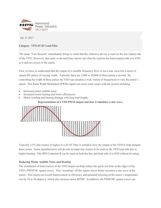
Hammond d v dt load filter
- 1. Jul. 31 2017 Category: VFD dV/dT Load Filter The name “Line Reactor” immediately brings to mind that this inductive device is used on the line (input) side of the VFD. However, that same or de-rated line reactor can often be used on the load (output) side of a VFD as it delivers power to the motor. First, we have to understand that the output of a variable frequency drive is not a sine wave but a series of square DC pulses of varying width. Typically there are 2,000 to 20,000 of these pulses a second. By controlling the width of these pulses the VFD can simulate a wide variety of frequencies to vary the motor’s speed. This Pulse Width Modulated (PWM) signal can cause some issues with the system including: Increased motor audible noise Increased motor heating and lower efficiencies Motor winding and bearing damage with long lead lengths Representation of a VFD PWM output and how it simulates a sine wave. Typically a 5% line reactor or higher or a dV/dT filter is installed close the output of the VFD to help mitigate these issues. Some manufacturers will de-rate an input line reactor to be used on the VFD load side due to higher heating. The HPS Centurion R can be used on both the line and load side of a VFD without de-rating. Reducing Motor Audible Noise and Heating The installation of load reactors at the VFD output can help reduce the quick rise time at the edges of the VFD’s PWM DC square waves. This “rounding” off the square waves better recreates a sine wave at the motor. This causes an overall improvement in efficiency and potential lowering of the motor’s temperature rise by 10 to 20 degree C which also increase motor MTBF. In addition, the PWM DC square waves can
- 2. cause a higher pitched audible whine in a motor. Adding an output line reactor can reduce the audible motor noise by 3 dB or more. Motor Winding and Bearing Damage with long lead lengths. Drive manufactures will typically designate a wire length between the VFD and motor that if exceeded, a reflected wave phenomenon may occur. In this instance, the output voltage of the drive can be multiplied by either two or four times the base voltage. This typically occurs somewhere in the motor windings or cable run. If this occurs it typically manifests itself as: Over-Voltage Cable Failures Motor Winding Insulation Failure Bearing failure: o The high voltage charge escapes the winding’s insulation but does not cause immediate insulation failure. One of the most likely paths to ground for the charge is through the windings, across the bearings and through the motor shaft to the grounded machinery. The arcing through the lubricant on the motor bearings causes tiny pits to form. If enough pits form, bearing failure will occur. While a line reactor may also help mitigate the issue, a dV/dT filter will better lower the top voltage of the reflected wave, especially at longer lead lengths. If using a line reactor, a minimum of 5% is recommended, higher impedances can be achieved by wiring 2 reactors in series. Typically adding a dV/dT filter to the output of a VFD will increase the rise time of the edge of the DC pulses and mitigate issues with reflected waves. A dV/dT filter combines a line reactor with an RC filter board that acts as a snubber circuit. If the VFD to motor distances exceeds 1000’, other technologies such as sine wave filters may need to be considered.