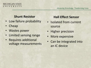
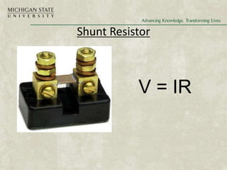
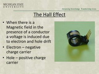
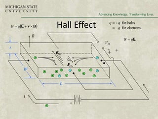
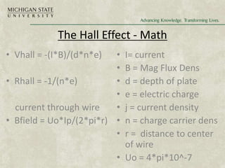
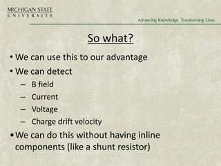
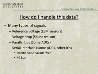
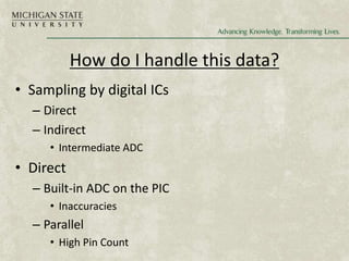
Team 2
Solar Kiosk Project
Sponsored by:
Team Members:
Jakub Mazur - Manager
Eric Tarkleson – Presentation/Lab
Josh Wong - Webmaster
Ben Kershner – Document Preparation
Current Sensing
• Applications
• Pros Cons
• The Hall Effect
• Shunt Resistors
• Making your Data useful
• Questions
Applications
• Measuring Power Consumption
• Design for Safety
– GFCIs, fuses, circuit breakers
• Temperature optimization
– High current = hotter components
Shunt Resistor
• Low failure probability
• Cheap
• Wastes power
• Limited sensing range
• Requires additional
voltage measurements
Hall Effect Sensor
• Isolated from current
source
• Higher precision
• More expensive
• Can be integrated into
an IC device
Who is this Guy?
André-Marie Ampère (1775 –1836)
By1800 scientists where wondering if
electricity and magnetism where related.
Ampere was one of the first to develop a
technique for measuring electricity…
essentially a compass with wire wrapped
around it.
Electrodynamics  Electromagnetics,
where studied at this time by: Faraday,
Weber Thomson and Maxwell.
Shunt Resistor
V = IR
The Hall Effect
• When there is a
Magnetic field in the
presence of a conductor
a voltage is induced due
to electron and hole drift
• Electron – negative
charge carrier
• Hole – positive charge
carrier
Hall Effect
VH
L
W
t
+
I
B
EHp
EHn
 
B
v
F 

 E
q
E
q

F
electrons
for
holes
for
q
q
q




+ +
+
The Hall Effect - Math
• Vhall = -(I*B)/(d*n*e)
• Rhall = -1/(n*e)
current through wire
• Bfield = Uo*Ip/(2*pi*r)
• I= current
• B = Mag Flux Dens
• d = depth of plate
• e = electric charge
• j = current density
• n = charge carrier dens
• r = distance to center
of wire
• Uo = 4*pi*10^-7
So what?
• We can use this to our advantage
• We can detect
– B field
– Current
– Voltage
– Charge drift velocity
•We can do this without having inline
components (like a shunt resistor)
How do I handle this data?
• Many types of signals
– Reference voltage (LEM sensors)
– Voltage drop (Shunt resistor)
– Parallel bus (Some ADCs)
– Serial interface (Some ADCs, other ICs)
• Traditional Serial Interface
• I2C Bus
How do I handle this data?
• Sampling by digital ICs
– Direct
– Indirect
• Intermediate ADC
• Direct
– Built-in ADC on the PIC
• Inaccuracies
– Parallel
• High Pin Count
Serial Buses
• Traditional UART/USART Serial
– Typically one-to-one communication
– Parity checking
• Serial Protocols
– I2C
• Developed by Philips
• 128 Devices on one bus
– USB
• Driver implementation

Technical_lecture.ppt

  • 1.
    Team 2 Solar KioskProject Sponsored by: Team Members: Jakub Mazur - Manager Eric Tarkleson – Presentation/Lab Josh Wong - Webmaster Ben Kershner – Document Preparation
  • 2.
    Current Sensing • Applications •Pros Cons • The Hall Effect • Shunt Resistors • Making your Data useful • Questions
  • 3.
    Applications • Measuring PowerConsumption • Design for Safety – GFCIs, fuses, circuit breakers • Temperature optimization – High current = hotter components
  • 4.
    Shunt Resistor • Lowfailure probability • Cheap • Wastes power • Limited sensing range • Requires additional voltage measurements Hall Effect Sensor • Isolated from current source • Higher precision • More expensive • Can be integrated into an IC device
  • 5.
    Who is thisGuy? André-Marie Ampère (1775 –1836) By1800 scientists where wondering if electricity and magnetism where related. Ampere was one of the first to develop a technique for measuring electricity… essentially a compass with wire wrapped around it. Electrodynamics  Electromagnetics, where studied at this time by: Faraday, Weber Thomson and Maxwell.
  • 6.
  • 7.
    The Hall Effect •When there is a Magnetic field in the presence of a conductor a voltage is induced due to electron and hole drift • Electron – negative charge carrier • Hole – positive charge carrier
  • 8.
    Hall Effect VH L W t + I B EHp EHn   B v F   E q E q  F electrons for holes for q q q     + + +
  • 9.
    The Hall Effect- Math • Vhall = -(I*B)/(d*n*e) • Rhall = -1/(n*e) current through wire • Bfield = Uo*Ip/(2*pi*r) • I= current • B = Mag Flux Dens • d = depth of plate • e = electric charge • j = current density • n = charge carrier dens • r = distance to center of wire • Uo = 4*pi*10^-7
  • 10.
    So what? • Wecan use this to our advantage • We can detect – B field – Current – Voltage – Charge drift velocity •We can do this without having inline components (like a shunt resistor)
  • 11.
    How do Ihandle this data? • Many types of signals – Reference voltage (LEM sensors) – Voltage drop (Shunt resistor) – Parallel bus (Some ADCs) – Serial interface (Some ADCs, other ICs) • Traditional Serial Interface • I2C Bus
  • 12.
    How do Ihandle this data? • Sampling by digital ICs – Direct – Indirect • Intermediate ADC • Direct – Built-in ADC on the PIC • Inaccuracies – Parallel • High Pin Count
  • 13.
    Serial Buses • TraditionalUART/USART Serial – Typically one-to-one communication – Parity checking • Serial Protocols – I2C • Developed by Philips • 128 Devices on one bus – USB • Driver implementation

Editor's Notes

  • #3 The “no roof” thing is a funny segue for the next slide…
  • #4 The “no roof” thing is a funny segue for the next slide…
  • #5 The “no roof” thing is a funny segue for the next slide…
  • #7 The “no roof” thing is a funny segue for the next slide…
  • #8 Draw on board the picture
  • #9 Draw on board the picture
  • #10 Draw on board the picture
  • #14 UART = universal asynchronous receiver/transmitter USART = universal synchronous/asynchronous receiver/transmitter