lecture-3 sensors and actuators for automatic systems.pptx
1.
1
Sensors & Actuatorsfor Automatic Systems
(S&AAS)
Dr. Imtiaz Hussain
Associate Professor
email: imtiaz.hussain@faculty.muet.edu.pk
URL :http://imtiazhussainkalwar.weebly.com/
Lecture-3
Hall Effect Sensor
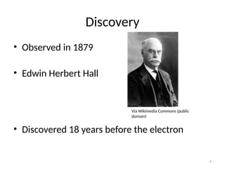
Discovery
• Observed in1879
• Edwin Herbert Hall
• Discovered 18 years before the electron
4
Via Wikimedia Commons (public
domain)
5.
5
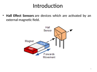
Introduction
• We knowthat a magnetic field has two important characteristics
flux density, (B) and polarity (North and South Poles).
• The output signal from a Hall effect sensor is the function of
magnetic field density around the device.
• When the magnetic flux density around the sensor exceeds a
certain pre-set threshold, the sensor detects it and generates an
output voltage called the Hall Voltage, VH.
6.
6
Lorentz Force
• Theforce which is exerted by a magnetic field on a moving
electric charge.
• The Lorentz force is the combination of electric and
magnetic force on a point charge due to electromagnetic fields.
• If a particle of charge q moves with velocity in the presence of
an electric field E and a magnetic field B, then it will experience a
force
𝑭 =𝑞[𝑬 +(𝒗 × 𝑩)]
7.
7
Hall Effect
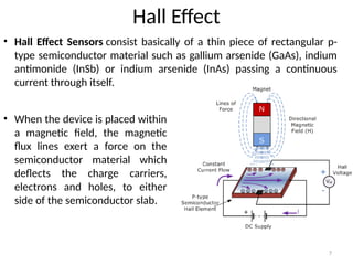
• HallEffect Sensors consist basically of a thin piece of rectangular p-
type semiconductor material such as gallium arsenide (GaAs), indium
antimonide (InSb) or indium arsenide (InAs) passing a continuous
current through itself.
• When the device is placed within
a magnetic field, the magnetic
flux lines exert a force on the
semiconductor material which
deflects the charge carriers,
electrons and holes, to either
side of the semiconductor slab.
8.
8
Hall Effect
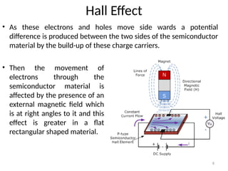
• Asthese electrons and holes move side wards a potential
difference is produced between the two sides of the semiconductor
material by the build-up of these charge carriers.
• Then the movement of
electrons through the
semiconductor material is
affected by the presence of an
external magnetic field which
is at right angles to it and this
effect is greater in a flat
rectangular shaped material.
9.
9
Hall Effect
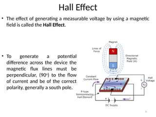
• Theeffect of generating a measurable voltage by using a magnetic
field is called the Hall Effect.
• To generate a potential
difference across the device the
magnetic flux lines must be
perpendicular, (90o
) to the flow
of current and be of the correct
polarity, generally a south pole.
10.
10
Hall Effect MagneticSensor
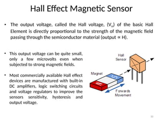
• The output voltage, called the Hall voltage, (VH) of the basic Hall
Element is directly proportional to the strength of the magnetic field
passing through the semiconductor material (output H).
∝
• This output voltage can be quite small,
only a few microvolts even when
subjected to strong magnetic fields.
• Most commercially available Hall effect
devices are manufactured with built-in
DC amplifiers, logic switching circuits
and voltage regulators to improve the
sensors sensitivity, hysteresis and
output voltage.
11.
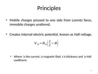
Principles
• Mobile chargespressed to one side from Lorentz force,
immobile charges unaltered.
• Creates internal electric potential, known as Hall voltage.
• Where is the current, is magnetic filed, t is thickness and is Hall
coefficient.
11
𝑉 𝐻 =𝑅𝐻 (𝐼
𝑡
× 𝐵)
12.
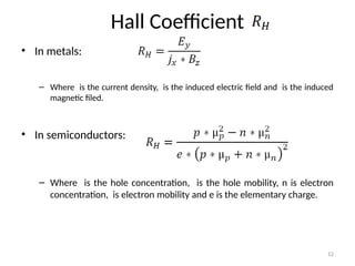
Hall Coefficient
• Inmetals:
– Where is the current density, is the induced electric field and is the induced
magnetic filed.
• In semiconductors:
– Where is the hole concentration, is the hole mobility, n is electron
concentration, is electron mobility and e is the elementary charge.
12
13.
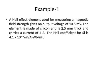
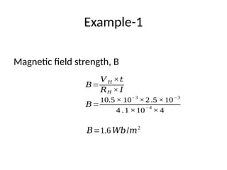
Example-1
• A Halleffect element used for measuring a magnetic
field strength gives on output voltage of 10.5 mV. The
element is made of silicon and is 2.5 mm thick and
carries a current of 4 A. The Hall coefficient for Si is
4.1 x 10⁻⁶
Vm/A-Wb/m2
.
14.
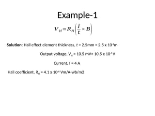
Example-1
Solution: Hall effectelement thickness, t = 2.5mm = 2.5 x 10⁻³
m
Output voltage, VH = 10.5 mV= 10.5 x 10⁻³
V
Current, I = 4 A
Hall coefficient, RH = 4.1 x 10⁻⁶
Vm/A-wb/m2
𝑉 𝐻 =𝑅𝐻 (𝐼
𝑡
× 𝐵)
16
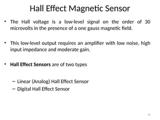
Hall Effect MagneticSensor
• The Hall voltage is a low-level signal on the order of 30
microvolts in the presence of a one gauss magnetic field.
• This low-level output requires an amplifier with low noise, high
input impedance and moderate gain.
• Hall Effect Sensors are of two types
– Linear (Analog) Hall Effect Sensor
– Digital Hall Effect Sensor
17.
17
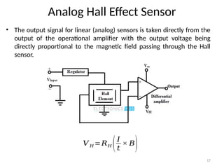
Analog Hall EffectSensor
• The output signal for linear (analog) sensors is taken directly from the
output of the operational amplifier with the output voltage being
directly proportional to the magnetic field passing through the Hall
sensor.
𝑉 𝐻 =𝑅𝐻 (𝐼
𝑡
× 𝐵)
18.
18
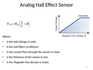
Analog Hall EffectSensor
𝑉 𝐻 =𝑅𝐻 (𝐼
𝑡
× 𝐵)
Where:
• is the Hall Voltage in volts
• is the Hall Effect co-efficient
• is the current flow through the sensor in amps
• is the thickness of the sensor in mm
• is the Magnetic Flux density in Teslas
19.
19
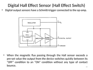
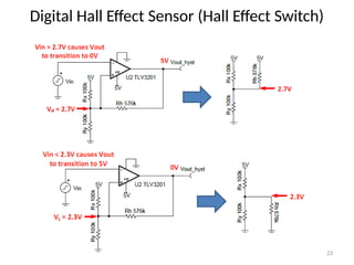
Digital Hall EffectSensor (Hall Effect Switch)
• Digital output sensors have a Schmitt-trigger connected to the op-amp.
• When the magnetic flux passing through the Hall sensor exceeds a
pre-set value the output from the device switches quickly between its
“OFF” condition to an “ON” condition without any type of contact
bounce.
20.
20
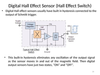
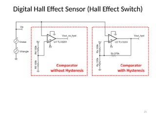
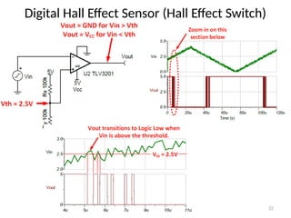
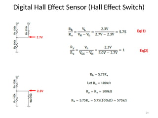
Digital Hall EffectSensor (Hall Effect Switch)
• Digital Hall effect sensors usually have built in hysteresis connected to the
output of Schmitt trigger.
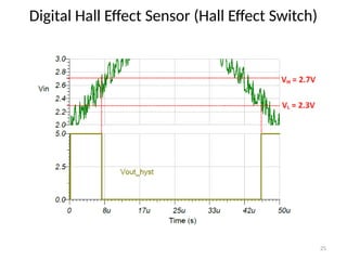
• This built-in hysteresis eliminates any oscillation of the output signal
as the sensor moves in and out of the magnetic field. Then digital
output sensors have just two states, “ON” and “OFF”.
26
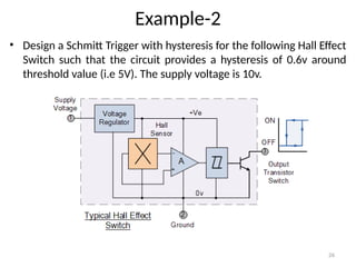
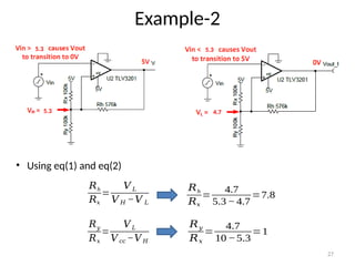
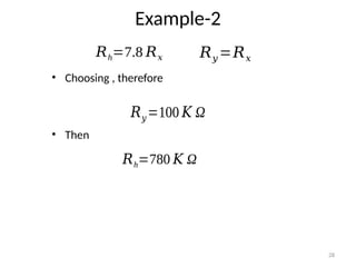
Example-2
• Design aSchmitt Trigger with hysteresis for the following Hall Effect
Switch such that the circuit provides a hysteresis of 0.6v around
threshold value (i.e 5V). The supply voltage is 10v.
30
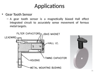
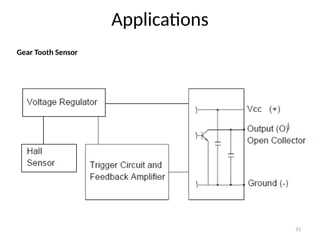
Applications
• Gear ToothSensor
– A gear tooth sensor is a magnetically biased Hall effect
integrated circuit to accurately sense movement of ferrous
metal targets.
32
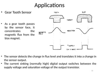
Applications
• Gear ToothSensor
• The sensor detects the change in flux level and translates it into a change in
the sensor output.
• The current sinking (normally high) digital output switches between the
supply voltage and saturation voltage of the output transistor.
• As a gear tooth passes
by the sensor face, it
concentrates the
magnetic flux from the
bias magnet.
33.
33
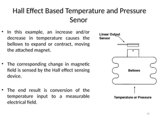
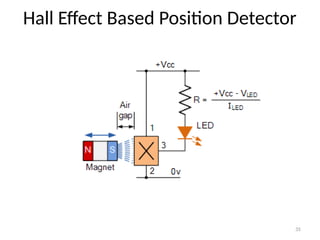
Hall Effect BasedTemperature and Pressure
Senor
• In this example, an increase and/or
decrease in temperature causes the
bellows to expand or contract, moving
the attached magnet.
• The corresponding change in magnetic
field is sensed by the Hall effect sensing
device.
• The end result is conversion of the
temperature input to a measurable
electrical field.
34.
34
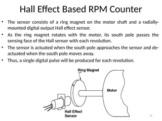
Hall Effect BasedRPM Counter
• The sensor consists of a ring magnet on the motor shaft and a radially-
mounted digital output Hall effect sensor.
• As the ring magnet rotates with the motor, its south pole passes the
sensing face of the Hall sensor with each revolution.
• The sensor is actuated when the south pole approaches the sensor and de-
actuated when the south pole moves away.
• Thus, a single digital pulse will be produced for each revolution.
36
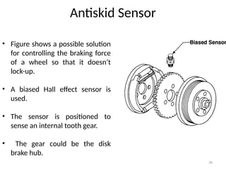
Antiskid Sensor
• Figureshows a possible solution
for controlling the braking force
of a wheel so that it doesn’t
lock-up.
• A biased Hall effect sensor is
used.
• The sensor is positioned to
sense an internal tooth gear.
• The gear could be the disk
brake hub.
37.
37
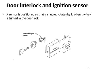
Door interlock andignition sensor
• A sensor is positioned so that a magnet rotates by it when the key
is turned in the door lock.
38.
38
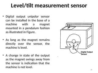
Level/tilt measurement sensor
•Digital output unipolar sensor
can be installed in the base of a
machine with a magnet
mounted in a pendulum fashion
as illustrated in Figure.
• As long as the magnet remains
directly over the sensor, the
machine is level.
• A change in state of the output
as the magnet swings away from
the sensor is indication that the
machine is not level.
39.
39
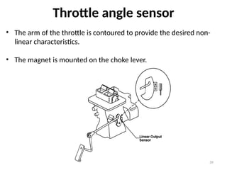
Throttle angle sensor
•The arm of the throttle is contoured to provide the desired non-
linear characteristics.
• The magnet is mounted on the choke lever.

![6
Lorentz Force
• The force which is exerted by a magnetic field on a moving
electric charge.
• The Lorentz force is the combination of electric and
magnetic force on a point charge due to electromagnetic fields.
• If a particle of charge q moves with velocity in the presence of
an electric field E and a magnetic field B, then it will experience a
force
𝑭 =𝑞[𝑬 +(𝒗 × 𝑩)]](https://image.slidesharecdn.com/lecture-3-250323043504-e62fb66b/85/lecture-3-sensors-and-actuators-for-automatic-systems-pptx-6-320.jpg)