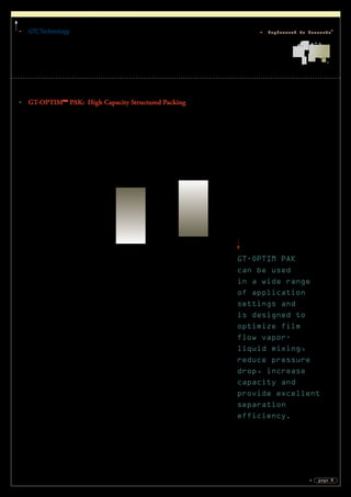
This document provides information on various types of structured packing solutions from GTC Technology. It begins with an introduction to structured packing and then describes different product lines including GT-PAK for conventional structured packing, GT-OPTIM PAK for high capacity structured packing, and GT-AQUA PAK for aqueous services. Graphs are included comparing the performance of structured packing to random packing in terms of efficiency, capacity, pressure drop and other factors. The document contains technical details on material properties and performance characteristics for proper selection of structured packing products.

![GTCTechnology
page 6
Engineered to Innovate®
Clients can
minimize energy
use while improving
product yield by
revamping process
towers with GTC
structured packing.
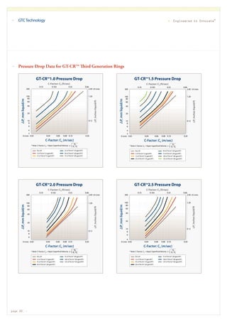
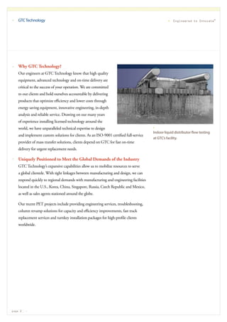
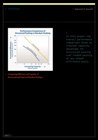
Comparing Pressure Drop and Capacity
of Structured and Random Packing
The relationship between pressure drop and capacity of structured and random
packing can be observed in the graph above. When conventional 250 m2
/m3
corrugated sheet structured packing is compared to #50 third-generation random
packing, structured packing has a greater capacity while maintaining a lower
pressure drop. When clients are looking to reduce energy costs and improve
column efficiency, GTC recommends revamping existing packed and trayed
columns with structured packing.
As displayed in the graph above, the random packing pressure drop is 15-20
percent higher than structured packing at the same column diameter and
throughput. Clients can benefit from structured packing by revamping existing
towers, reducing new column cross sectional area by 15-20 percent, improving
product purities and minimizing operating costs.
Performance Comparison
Structured Packing vs Random Packing
20
10
5
3
2
1
0.5
0.3
0.2
0.1
0.05
0.02 0.04 0.06 0.08 0.1
0.20
0.12
0.08
0.04
0.02
0.40
0.80
1.20
2.0
4.0
8.0
0.33 0.360.260.200.130.066 Cs [ft/s] =
NOTES:
1. Typical“Low-Alpha”Hydrocarbon System shown.
2. HETP Values are System Dependent.
Design Safety Factors must be added.
SI Units
US Units
InchesWC/Theoreticalstage
0.11
IncreasingPressureDrop
mbar/Theoreticalstage
Increasing Capacity
Capacity Factor, CS [m/s]
Random Rings #50 3rd Generation
Structured Pack 250Y
Conventi
onal](https://image.slidesharecdn.com/gt-packedtower-140421122724-phpapp02/85/High-Performance-Packed-Tower-Solutions-8-320.jpg)
![GTCTechnology
page 7
Engineered to Innovate®
Utilize this
graph to quickly
estimate minimum
bed heights and
minimum column
diameter for two
common packing
types in refinery
applications.
Estimations can
be based on typical
simulation results
for quantity of
theoretical stages
and internal flow
rates required
to meet the
specified product
compositions.
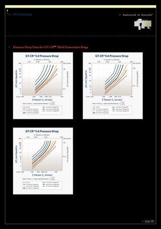
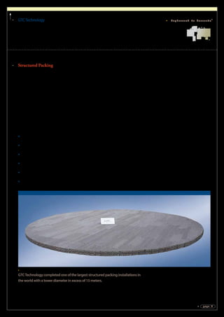
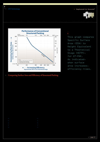
Comparing Efficiency and Capacity
of Structured and Random Packing
When comparing the efficiency and capacity of structured packing to random
packing, structured packing has significantly better performance.
There is a significant difference between the performance of GT-PAK 250Y
corrugated sheet structured packing and #50 third-generation random packing.
GT-PAK 250Y requires 50 percent less bed height for the same separation in
sizing new columns and can maintain greater capacity compared to random
rings. For revamped columns bed heights can be maintained, while a larger crimp
size structured packing can gain up to 50 percent greater capacity and yield the
same product purities as the #50 third-generation random packing. In addition,
clients can gain 10 percent more through-put, with better product purities at the
same column diameter or smaller by using GT-PAK 250Y as opposed to third-
generation random packing.
Notes:
1. The data represents a typical refinery application at atmospheric pressure.
2. A 10 percent minimum safety factor of added bed height is recommended to allow for feed
composition and operating control variations.
3. It is typical for new column sizing to be conservatively estimated at about 75 percent flood to
allow for future increases at efficient operation.
4. An 85 percent flood is considered a maximum safe design for revamp projects.
5. The maximum efficient column operation is around 90 percent flood for most modern packing.
Performance Comparison
Structured Packing vs Random Packing
1200
1000
800
600
400
200
0
0 .05 1 1.5 2.52
47.2
39.4
31.5
23.6
15.7
7.9
1.23 1.64 2.05 2.460.820.41Fs [ft/s] =
NOTES:
1. Typical Refinery Application, Atmospheric Pressure
2. HETP Values are System Dependent.
Design Safety Factors must be added.
SI Units
US Units
InchesWC/Theoreticalstage
3
HETP,mm
HeightEquivalenttoTheoreticalstage
Increasing Capacity
Vapor Rate: F-Factor, Fs = V5
*Dv0.5
[m/s]
HETP,Inches
RandomRings#503rdGeneration
StructuredPack250YConventional](https://image.slidesharecdn.com/gt-packedtower-140421122724-phpapp02/85/High-Performance-Packed-Tower-Solutions-9-320.jpg)