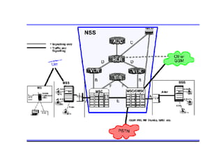
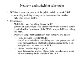
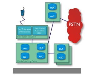
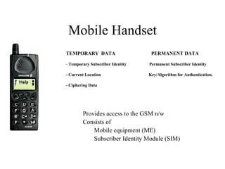
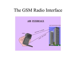
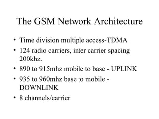
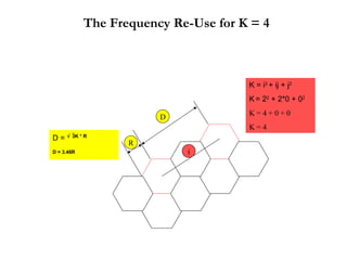
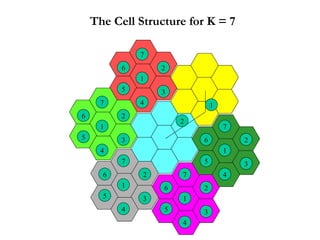
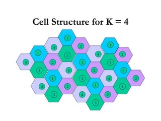
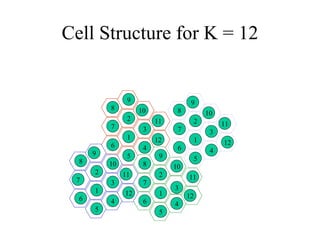
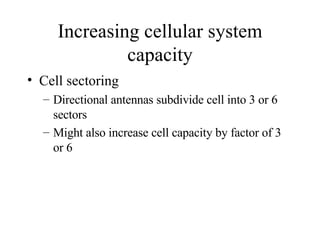
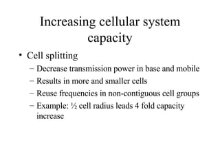
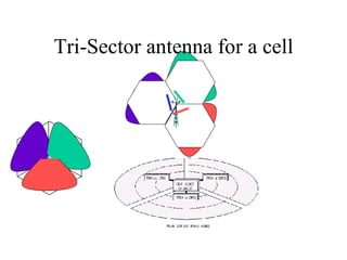
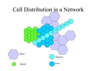
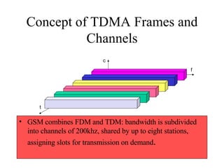
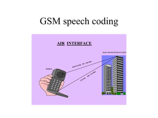
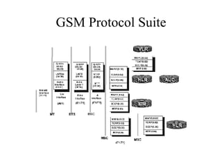
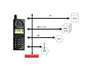
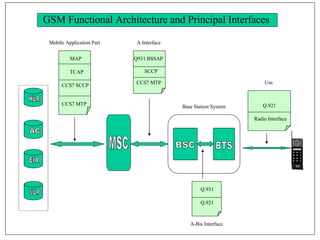
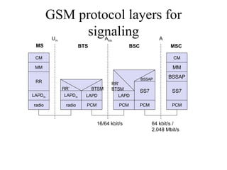
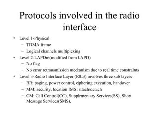
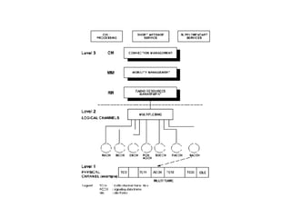
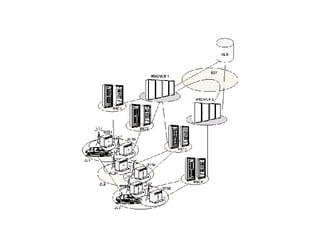
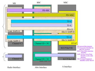
Overview of GSM Cellular Network and Operations Ganesh Srinivasan NTLGSPTN
 
Network and switching subsystem NSS is the main component of the public mobile network GSM switching, mobility management, interconnection to other networks, system control Components Mobile Services Switching Center (MSC) controls all connections via a separated network to/from a mobile terminal within the domain of the MSC - several BSC can belong to a MSC Databases (important: scalability, high capacity, low delay) Home Location Register (HLR) central master database containing user data, permanent and semi-permanent data of all subscribers assigned to the HLR (one provider can have several HLRs) Visitor Location Register (VLR) local database for a subset of user data, including data about all user currently in the domain of the VLR
 
Operation subsystem The OSS (Operation Subsystem) enables centralized operation, management, and maintenance of all GSM subsystems Components Authentication Center (AUC) generates user specific authentication parameters on request of a VLR  authentication parameters used for authentication of mobile terminals and encryption of user data on the air interface within the GSM system  Equipment Identity Register (EIR) registers GSM mobile stations and user rights stolen or malfunctioning mobile stations can be locked and sometimes even localized Operation and Maintenance Center (OMC) different control capabilities for the radio subsystem and the network subsystem
Mobile Handset TEMPORARY  DATA  PERMANENT DATA -  Temporary Subscriber Identity  Permanent Subscriber Identity - Current Location  Key/Algorithm for Authentication. - Ciphering Data Provides access to the GSM n/w Consists of Mobile equipment (ME) Subscriber Identity Module (SIM)
The GSM Radio Interface
The GSM Network Architecture Time division multiple access-TDMA 124 radio carriers, inter carrier spacing 200khz. 890 to 915mhz mobile to base - UPLINK 935 to 960mhz base to mobile - DOWNLINK 8 channels/carrier
GSM uses paired radio channels 0 124 0 124 890MHz 915MHz 935MHz 960MHz UPLINK DOWNLINK
Access Mechanism FDMA, TDMA, CDMA
Frequency multiplex Separation of the whole spectrum into smaller frequency bands A channel gets a certain band of the  spectrum for the whole time Advantages: no dynamic coordination  necessary works also for analog signals Disadvantages: waste of bandwidth  if the traffic is  distributed unevenly inflexible guard spaces k 2 k 3 k 4 k 5 k 6 k 1 f t c
Time multiplex A channel gets the whole spectrum for a certain amount of time Advantages: only one carrier in the medium at any time throughput high even  for many users Disadvantages: precise  synchronization  necessary k 2 k 3 k 4 k 5 k 6 k 1 f t c
Time and Frequency Multiplex Combination of both methods A channel gets a certain frequency band for a certain amount of time f t c k 2 k 3 k 4 k 5 k 6 k 1
Time and Frequency Multiplex Example: GSM  Advantages: Better protection against  tapping Protection against frequency  selective interference Higher data rates compared to code multiplex But: precise coordination required f t c k 2 k 3 k 4 k 5 k 6 k 1
GSM combines FDM and TDM: bandwidth is subdivided into channels of 200khz, shared by up to eight stations, assigning slots for transmission on demand.
GSM uses paired radio channels 0 124 0 124 890MHz 915MHz 935MHz 960MHz UPLINK DOWNLINK
Code Multiplex Each channel has a unique code All channels use the same spectrum at the same time Advantages: Bandwidth efficient No coordination and synchronization necessary Good protection against interference and tapping Disadvantages: Lower user data rates More complex signal regeneration Implemented using spread spectrum technology k 2 k 3 k 4 k 5 k 6 k 1 f t c
Various Access Method
Cells
Capacity & Spectrum Utilization Solution The need: Optimum spectrum usage More capacity High quality of service Low cost I wish I could  increase capacity without   adding NEW BTS! What can I do? Network capacity at  required QoS with conventional frequency plan Subscriber  growth Time Out of  Capacity!!!
Representation of Cells Ideal cells Fictitious cells
Cell size and capacity Cell size determines number of cells available to cover geographic area and (with frequency reuse) the total capacity available to all users Capacity within cell limited by available bandwidth and operational requirements Each network operator has to size cells to handle expected traffic demand
Cell structure Implements space division multiplex: base station covers a certain transmission area (cell) Mobile stations communicate only via the base station Advantages of cell structures: higher capacity, higher number of users less transmission power needed more robust, decentralized base station deals with interference, transmission area etc. locally Problems: fixed network needed for the base stations handover (changing from one cell to another) necessary interference with other cells Cell sizes from some 100 m in cities to, e.g., 35 km on the country side (GSM) - even less for higher frequencies
Capacity of a Cellular System Frequency Re-Use Distance The K factor or the cluster size Cellular coverage or Signal to interference ratio Sectoring
The K factor and Frequency Re-Use Distance i j 1 2 3 4 5 6 7 Frequency re-use distance is based on the cluster size K The cluster size is specified in terms of the offset of the center of a cluster from the center of the adjacent cluster K = i 2  + ij + j 2   K   = 2 2  + 2*1 + 1 2 K = 4 + 2 + 1   K = 7 D =   3K * R D = 4.58R   1 2 3 5 6 7 D R
The Frequency Re-Use for K = 4 K = i 2  + ij + j 2   K   = 2 2  + 2*0 + 0 2 K = 4 + 0 + 0   K = 4 D =   3K * R D = 3.46R i D R
The Cell Structure for K = 7 1 2 3 4 5 6 7 1 2 3 4 5 6 7 2 1 1 2 3 4 5 6 7 1 2 3 4 5 6 7 1 2 3 4 5 6 7
Cell Structure for K = 4 1 2 3 4 1 1 1 1 1 1 2 2 2 2 2 3 3 3 3 3 4 4 4 4 4 4 3 2
Cell Structure for K = 12 1 1 1 1 2 2 2 2 3 3 3 3 4 4 4 4 5 5 5 5 6 6 6 6 7 7 7 7 8 8 8 8 9 9 9 9 10 10 10 10 11 11 11 11 12 12 12 12
Increasing cellular system capacity Cell sectoring Directional antennas subdivide cell into 3 or 6 sectors Might also increase cell capacity by factor of 3 or 6
Increasing cellular system capacity Cell splitting Decrease transmission power in base and mobile Results in more and smaller cells Reuse frequencies in non-contiguous cell groups Example: ½ cell radius leads 4 fold capacity increase
Tri-Sector antenna for a cell
Cell Distribution in a Network Highway Town Suburb Rural
Optimum use of frequency spectrum Operator bandwidth of 7.2MHz (36 freq of 200 kHz) TDMA 8 traffic channels per carrier K factor = 12 What are the number of traffic channels available within its area for these three cases Without cell splitting With 72 cells With 246 cells
Re-use of the frequency One Cell = 288 traffic channels 72 Cell = 1728 traffic channels 246 Cell = 5904 traffic channels 8 X 36 = 288 8 X (72/12 X 36) = 1728
Concept of TDMA Frames and Channels GSM combines FDM and TDM: bandwidth is subdivided into channels of 200khz, shared by up to eight stations, assigning slots for transmission on demand . f t c
GSM uses paired radio channels 0 124 0 124 890MHz 915MHz 935MHz 960MHz UPLINK DOWNLINK
GSM delays uplink TDMA frames Uplink TDMA Frame  F1 + 45MHz Downlink TDMA F1MHz The start of the uplink TDMA is delayed of three time slots TDMA frame (4.615 ms) Fixed transmit  Delay of three time-slots T1 T2 T3 T5 T6 T7 T4 T8 R T R T R1 R2 R3 R5 R6 R7 R4 R8
GSM - TDMA/FDMA 935-960 MHz 124 channels (200 kHz) downlink 890-915 MHz 124 channels (200 kHz) uplink frequency time GSM TDMA frame GSM time-slot (normal burst) guard space guard space 1 2 3 4 5 6 7 8 higher GSM frame structures 4.615 ms 546.5 µs 577 µs tail user data Training S S user data tail 3 bits 57 bits 26 bits 57 bits 1 1 3
LOGICAL CHANNELS TRAFFIC SIGNALLING FULL RATE Bm  22.8 Kb/S HALF RATE Lm  11.4 Kb/S BROADCAST COMMON CONTROL  DEDICATED CONTROL FCCH SCH BCCH PCH RACH AGCH SDCCH SACCH FACCH FCCH  -- FREQUENCY CORRECTION CHANNEL SCH  --  SYNCHRONISATION CHANNEL BCCH  -- BROADCAST CONTROL CHANNEL PCH  -- PAGING CHANNEL RACH  -- RANDOM ACCESS  CHANNEL AGCH  -- ACCESS GRANTED  CHANNEL SDCCH -- STAND ALONE DEDICATED CONTROL CHANNEL SACCH -- SLOW ASSOCIATED CONTROL CHANNEL FACCH -- FAST ASSOCIATED CONTROL CHANNEL DOWN LINK ONLY UPLINK ONLY BOTH UP & DOWNLINKS
Broadcast Channel - BCH Broadcast control channel (BCCH) is a base to mobile channel which provides general information about the network, the cell in which the mobile is currently located and the adjacent cells Frequency correction channel (FCCH) is a base to mobile channel which provides information for carrier synchronization Synchronization channel (SCH) is a base to mobile channel which carries information for frame synchronization and identification of the base station transceiver
Common Control Channel - CCH Paging channel (PCH) is a base to mobile channel used to alert a mobile to a call originating from the network Random access channel (RACH) is a mobile to base channel used to request for dedicated resources Access grant channel (AGCH) is a base to mobile which is used to assign dedicated resources (SDCCH or TCH)
Dedicated Control Channel - DCCH Stand-alone dedicated control channel (SDCCH) is a bi-directional channel allocated to a specific mobile for exchange of location update information and call set up information
Dedicated Control Channel - DCCH Slow associated control channel (SACCH) is a bi-directional channel used for exchanging control information between base and a mobile during the progress of a call set up procedure. The SACCH is associated with a particular traffic channel or stand alone dedicated control channel Fast associated control channel (FACCH) is a bi-directional channel which is used for exchange of time critical information between mobile and base station during the progress of a call. The FACCH transmits control information by stealing capacity from the associated TCH
DEFINITION OF TIME SLOT - 156.25 BITS 15/26ms = 0.577ms TAIL BIT ENCRYPTION BIT GUARD PERIOD TRAINING  BITS MIXED BITS SYNCHRONISATION  BITS FIXED BITS FLAG BITS 3 57 1 26 1 57 3 8.25 NORMAL BURST  - NB 3 142 3 8.25 FREQUENCY CORRECTION  BURST - FB 3 3 8.25 39 64 39 SYNCHRONISATION  BURST - SB 3 6 41 36 68.25 ACCESS BURST - AB
0  1  2  3  4  5  6  2043  2044  2045  2046  2047 0  1  2  24  25 0  1  2  3  24  25 1 HYPER FRAME = 2048 SUPERFRAMES = 2 715 648 TDMA FRAMES  ( 3 H 28 MIN 53 S  760 MS ) 1 SUPER FRAME = 1326 TDMA FRAMES  ( 6.12 S ) LEFT  (OR)  RIGHT 1 MULTI FRAME = 51 TDMA  FRAMES  (235 .4 ms ) 1 SUPER FRAME = 26  MULTI FRAMES 1 SUPER FRAME = 51  MULTI FRAMES 1 MULTIFRAME = 26  TDMA  FRAMES  ( 120 ms ) TDMA FRAME NO. 0 1 0 1 HIERARCHY OF FRAMES 1  2  3  4  155  156  1 TIME SLOT = 156.25 BITS  ( 0.577 ms) (4.615ms) (4.615 ms) 1 bit =36.9 micro sec TRAFFIC CHANNELS SIGNALLING CHANNELS 0  1  2  3  4  48  49  50 0  1  2  3  4  48  49  50 0  1  2  3  4  5  6  7  0  1  2  3  4  5  6  7  0 0  1  2  3  4  5  6  7  0  1  2  3  4  5  6  7  0
GSM Frame Full rate channel is idle in 25 SACCH is transmitted in frame 12 0 to 11 and 13 to 24 Are used for traffic data Frame duration = 120ms Frame duration = 60/13ms Frame duration = 15/26ms 0  1  2  3  4  5  6  7 3 57 1 26 1 57 3 8.25 0  1  2  12  24  25
114 bits are available for data transmission. The training sequence of 26 bits in the middle of the burst is used by the receiver to synchronize and compensate for time dispersion produced by multipath propagation. 1 stealing bit for each information block (used for FACCH)
LOGICAL CHANNELS TRAFFIC SIGNALLING FULL RATE Bm  22.8 Kb/S HALF RATE Lm  11.4 Kb/S BROADCAST COMMON CONTROL  DEDICATED CONTROL FCCH SCH BCCH PCH RACH AGCH SDCCH SACCH FACCH FCCH  -- FREQUENCY CORRECTION CHANNEL SCH  --  SYNCHRONISATION CHANNEL BCCH  -- BROADCAST CONTROL CHANNEL PCH  -- PAGING CHANNEL RACH  -- RANDOM ACCESS  CHANNEL AGCH  -- ACCESS GRANTED  CHANNEL SDCCH -- STAND ALONE DEDICATED CONTROL CHANNEL SACCH -- SLOW ASSOCIATED CONTROL CHANNEL FACCH -- FAST ASSOCIATED CONTROL CHANNEL DOWN LINK ONLY UPLINK ONLY BOTH UP & DOWNLINKS
Location update from the mobile Mobile looks for BCCH after switching on RACH send channel request  AGCH receive SDCCH SDCCH authenticate SDCCH switch to cipher mode SDCCH request for location updating SDCCH authenticate response SDCCH cipher mode acknowledge SDCCH allocate TMSI SDCCH acknowledge new TMSI SDCCH switch idle update mode
Call establishment from a mobile Mobile looks for BCCH after switching on RACH send channel request  AGCH receive SDCCH SDCCH do the authentication and TMSI allocation SDCCH require traffic channel assignment SDCCH send call establishment request SDCCH send the setup message and desired number FACCH switch to traffic channel and send ack (steal bits) FACCH receive alert signal ringing sound FACCH acknowledge connect message and use TCH TCH conversation continues FACCH receive connect message
Call establishment to a mobile Mobile looks for BCCH after switching on Receive signaling channel SDCCH on AGCH Receive alert signal and generate ringing on FACCH Receive authentication request on SDCCH Generate Channel Request on RACH Answer paging message on SDCCH Authenticate on SDCCH Receive setup message on SDCCH FACCH acknowledge connect message and switch to TCH Receive connect message on FACCH Receive traffic channel assignment on SDCCH Mobile receives paging message on PCH FACCH switch to traffic channel and send ack (steal bits)
GSM speech coding
Transmit Path   BS Side 8 bit A-Law  to  13 bit Uniform RPE/LTP speech Encoder To Channel Coder 13Kbps 8 K sps MS Side LPF A/D RPE/LTP speech Encoder To Channel Coder 13Kbps 8 K sps, Sampling Rate - 8K Encoding - 13 bit Encoding (104 Kbps) RPE/LTP - Regular Pulse Excitation/Long Term Prediction RPE/LTP converts the 104 Kbps stream to 13 Kbps
GSM Speech Coding GSM is a digital system, so speech which is inherently analog, has to be digitized. The method employed by current telephone systems for multiplexing voice lines over high speed trunks and is pulse coded modulation (PCM). The output stream from PCM is 64 kbps, too high a rate to be feasible over a radio link.
GSM Frame Full rate channel is idle in 25 SACCH is transmitted in frame 12 0 to 11 and 13 to 24 Are used for traffic data Frame duration = 120ms Frame duration = 60/13ms Frame duration = 15/26ms 0  1  2  3  4  5  6  7 3 57 1 26 1 57 3 8.25 0  1  2  12  24  25
GSM Speech Coding Speech is divided into 20 millisecond samples, each of which is encoded as 260 bits, giving a total bit rate of 13 kbps.  Regular pulse excited -- linear predictive coder (RPE--LPC) with a long term predictor loop is the speech coding algorithm.
The 260 bits are divided into three classes: Class Ia 50 bits - most sensitive to bit errors. Class Ib 132 bits - moderately sensitive to bit errors. Class II 78 bits - least sensitive to bit errors. Class Ia bits have a 3 bit cyclic redundancy code added for error detection = 50+3 bits. 132 class Ib bits with 4 bit tail sequence = 132 + 4 = 136. Class Ia + class Ib = 53+136=189, input into a 1/2 rate convolution encoder of constraint length 4. Each input bit is encoded as two output bits, based on a combination of the previous 4 input bits. The convolution encoder thus outputs 378 bits, to which are added the 78 remaining class II bits. Thus every 20 ms speech sample is encoded as 456 bits, giving a bit rate of 22.8 kbps.
To further protect against the burst errors common to the radio interface, each sample is interleaved. The 456 bits output by the convolution encoder are divided into 8 blocks of 57 bits, and these blocks are transmitted in eight consecutive time-slot bursts. Since each time-slot burst can carry two 57 bit blocks, each burst carries traffic from two different speech samples.  3 57 bits 26  1 1 57 bits 3 3 57 bits 26  1 1 57 bits 3 3 57 bits 26  1 1 57 bits 3 3 57 bits 26  1 1 57 bits 3 3 57 bits 26  1 1 57 bits 3 3 57 bits 26  1 1 57 bits 3 3 57 bits 26  1 1 57 bits 3 3 57 bits 26  1 1 57 bits 3
GSM Protocol Suite
BTS Radio interface HLR MSC VLR BSC RR MM + CM SS
Link Layer LAPDm is used between MS and BTS LAPD  is used between BTS-BSC MTP2 is used between BSC-MSC/VLR/HLR
Network Layer To distinguish between CC, SS, MM and RR protocol discriminator (PD) is used as network address. CC call control management MS-MSC. SS supplementary services management MS-MSC/HLR. MM mobility management(location management, security management) MS-MSC/VLR. RR radio resource management MS-BSC. Messages pertaining to different transaction are distinguished by a transaction identifier (TI).
Application Layer protocols BSSMAP between BSC and MSC DTAP messages between MS and MSC. All messages on the A interface bear a discrimination flag, indicating whether the message is a BSSMAP or a DTAP. DTAP messages carry DLCI(information on type of link on the radio interface) to distinguish what is related to CC or SMS. MAP protocol is the one between neighbor MSCs. MAP is also used between MSC and HLR.
BSC BTS A-Bis Interface Um Base Station System GSM Functional Architecture and Principal Interfaces HLR AC EIR VLR MSC Q.921 Radio Interface Q.931 Q.921 MAP TCAP CCS7 MTP CCS7 SCCP Mobile Application Part Q931 BSSAP SCCP  CCS7 MTP A Interface
GSM protocol layers for signaling CM MM RR MM LAPD m radio LAPD m radio LAPD PCM RR’  BTSM CM LAPD PCM RR’ BTSM  16/64 kbit/s U m A bis A SS7 PCM SS7 PCM 64 kbit/s / 2.048 Mbit/s MS BTS BSC MSC BSSAP BSSAP
Protocols involved in the radio interface Level 1-Physical TDMA frame  Logical channels multiplexing Level 2-LAPDm(modified from LAPD) No flag No error retransmission mechanism due to real time constraints Level 3-Radio Interface Layer (RIL3) involves three sub layers RR: paging, power control, ciphering execution, handover MM: security, location IMSI attach/detach CM: Call Control(CC), Supplementary Services(SS), Short Message Services(SMS),
 
LAPDm on radio interface In LAPDm the use of flags is avoided. LAPDm maximum length is 21 octets of information. It makes use of “more” bit to distinguish last frame of a message. No frame check sequence for LAPDm, it uses the error detecting performance of the transmission coding scheme offered by the physical layer
LAPDm Message structure ADDRESS CONTROL INFORMATION 0-21 OCTETS SAPI N(S) N(R)
 
LAPDm on radio interface The acknowledgement for the next expected frame in the indicator N(R ). On radio interface two independent flows(one for signaling, and one for SMS) can exist simultaneously. These two flows are distinguished by a link identifier called the SAPI(service access point identifier). LAPDm SAPI=0 for signaling and SAPI=3 for SMS. SAP1=0 for radio signaling, SAPI=62 for OAM and SAPI=63 for layer 2 management on the Abis interface. There is no need of a TEI, because there is no need to distinguish the different mobile stations, which is done by distinguishing the different radio channels.
Protocols involved in the A-bis interface Level 1-PCM transmission (E1 or T1) Speech encoded at 16kbit/s and sub multiplexed in 64kbit/s time slots. Data which rate is adapted and synchronized. Level 2-LAPD protocol, standard HDLC Radio Signaling Link (RSL) Operation and Maintenance Link (OML). Level 3-Application Protocol Radio Subsystem Management (RSM) Operation and Maintenance procedure (OAM)
Presentation of A-bis Interface Messages exchanges between the BTS and BSC. Traffic exchanges Signaling exchanges Physical access between BTS and BSC is PCM digital links of E1(32) or T1(24) TS at 64kbit/s. Speech: Conveyed in timeslots at 4X16 kbit/s Data: Conveyed in timeslots of 4X16 kbit/s. The initial user rate, which may be 300, 1200, … is adjusted to 16 kbit/s
LAPD message structure FLAG ADRESS CONTROL INFORMATION 0 – 260 OCT FCS FLAG SAPI TEI N(S) N(R)
LAPD The length is limited to 260 octets of information. LAPD has the address of the destination terminal, to identify the TRX, since this is a point to multipoint interface. Each TRX in a BTS corresponds to one or several signaling links. These links are distinguished by TEI (Terminal Equipment Identities). SAPI=0, SAPI=3, SAPI=62 for OAM.
Presentation of the A-ter interface
BSC TRAU MSC OMC OAM Transcoding LAPD TS1 Speech TS CCS7 TS X.25 TS2 Speech TS CCS7 TS X.25 TS2 PCM LINK PCM LINK
Presentation on the A-ter interface Signaling messages are carried on specific timeslots (TS) LAPD signaling TS between the BSC and the TCU SS7 TS between the BSC and the MSC, dedicated for BSSAP messages transportation. X25 TS2 is reserved for OAM. Speech and data channels (16kbit/s) Ater interface links carry up to: 120 communications(E1), 4*30 92 communications(T1). The 64 kbit/s speech rate adjustment and the 64 kbit/s data rate adaptation are performed at the   TCU.
Presentation of the A interface
Signaling Protocol Model
Presentation on the A-Interface BSSMAP  - deals with procedures that take place  logically  between the  BSS  and  MSC , examples: Trunk Maintenance,   Ciphering, Handover, Voice/Data Trunk Assignment DTAP  - deals with procedures that take place  logically  between the  MS  and  MSC .  The  BSS  does not interpret the  DTAP  information, it simply repackages it and sends it to the  MS  over the Um Interface. examples: Location Update,   MS originated and terminated Calls, Short Message Service, User Supplementary Service registration, activation, deactivation and erasure
Inter MSC presentation
O A M L A P D BTS MTP2 SCCP MTP3 L A P D O A M R R D T A P B S S M A P BSSAP BSC MTP1 MTP3 MTP2 SCCP MTP2 MTP3 SCCP BSSAP DTAP/ BSSMAP T C A P MM CM M A P NSS R R MM CM MS LAPDm LAPDm RADIO RADIO PCM PCM PCM E1 T1 ISUP/TUP Um Interface A bis Interface A Interface
SCCP Ref=R2 TRX:TEI=T1 Channel ID = N1 SCCP Ref=R1 DTAP DLCI: SAPI=3 DLCI: SAPI=0 Channel=C1 Link: SAPI=3 Link: SAPI=0 PD=CC TI=a TI=b PD=MM PD=RR TI=A MS BSC MSC Channel=C2 Channel ID = N1 Radio Interface Abis Interface A Interface PD: protocol discriminator TI: Transaction Identifier for RIL3-CC protocol DLCI: Data Link connection  Identifier SAPI: Service Access Point  Identifier on the radio Interface TEI: Terminal Equipment  Identifier on the Abis I/F
Bearer Services Telecommunication services to transfer data between access points Specification of services up to the terminal interface (OSI layers 1-3)  Different data rates for voice and data (original standard) Data service  Synchronous: 2.4, 4.8 or 9.6 kbit/s Asynchronous: 300 - 1200 bit/s
Tele Services Telecommunication services that enable voice communication via mobile phones. All these basic services have to obey cellular functions, security measurements etc. Offered services. Mobile telephony primary goal of GSM was to enable mobile telephony offering the traditional bandwidth of 3.1 kHz. Emergency number common number throughout Europe (112); Mandatory for all service providers; Free of charge; Connection with the highest priority (preemption of other connections possible). Multinumbering several ISDN phone numbers per user possible.
Performance characteristics of GSM Communication  mobile, wireless communication; support for voice and data services Total mobility  international access, chip-card enables use of access points of different providers Worldwide connectivity one number, the network handles localization High capacity  better frequency efficiency, smaller cells, more customers per cell High transmission quality high audio quality and reliability for wireless, uninterrupted phone calls at higher speeds (e.g., from cars, trains) Security functions  access control, authentication via chip-card and PIN
Disadvantages of GSM No full ISDN bandwidth of 64 kbit/s to the user Reduced concentration while driving Electromagnetic radiation Abuse of private data possible High complexity of the system Several incompatibilities within the GSM standards
Thank You

Gsm1368

  • 1.
    Overview of GSMCellular Network and Operations Ganesh Srinivasan NTLGSPTN
  • 2.
  • 3.
    Network and switchingsubsystem NSS is the main component of the public mobile network GSM switching, mobility management, interconnection to other networks, system control Components Mobile Services Switching Center (MSC) controls all connections via a separated network to/from a mobile terminal within the domain of the MSC - several BSC can belong to a MSC Databases (important: scalability, high capacity, low delay) Home Location Register (HLR) central master database containing user data, permanent and semi-permanent data of all subscribers assigned to the HLR (one provider can have several HLRs) Visitor Location Register (VLR) local database for a subset of user data, including data about all user currently in the domain of the VLR
  • 4.
  • 5.
    Operation subsystem TheOSS (Operation Subsystem) enables centralized operation, management, and maintenance of all GSM subsystems Components Authentication Center (AUC) generates user specific authentication parameters on request of a VLR authentication parameters used for authentication of mobile terminals and encryption of user data on the air interface within the GSM system Equipment Identity Register (EIR) registers GSM mobile stations and user rights stolen or malfunctioning mobile stations can be locked and sometimes even localized Operation and Maintenance Center (OMC) different control capabilities for the radio subsystem and the network subsystem
  • 6.
    Mobile Handset TEMPORARY DATA PERMANENT DATA - Temporary Subscriber Identity Permanent Subscriber Identity - Current Location Key/Algorithm for Authentication. - Ciphering Data Provides access to the GSM n/w Consists of Mobile equipment (ME) Subscriber Identity Module (SIM)
  • 7.
    The GSM RadioInterface
  • 8.
    The GSM NetworkArchitecture Time division multiple access-TDMA 124 radio carriers, inter carrier spacing 200khz. 890 to 915mhz mobile to base - UPLINK 935 to 960mhz base to mobile - DOWNLINK 8 channels/carrier
  • 9.
    GSM uses pairedradio channels 0 124 0 124 890MHz 915MHz 935MHz 960MHz UPLINK DOWNLINK
  • 10.
  • 11.
    Frequency multiplex Separationof the whole spectrum into smaller frequency bands A channel gets a certain band of the spectrum for the whole time Advantages: no dynamic coordination necessary works also for analog signals Disadvantages: waste of bandwidth if the traffic is distributed unevenly inflexible guard spaces k 2 k 3 k 4 k 5 k 6 k 1 f t c
  • 12.
    Time multiplex Achannel gets the whole spectrum for a certain amount of time Advantages: only one carrier in the medium at any time throughput high even for many users Disadvantages: precise synchronization necessary k 2 k 3 k 4 k 5 k 6 k 1 f t c
  • 13.
    Time and FrequencyMultiplex Combination of both methods A channel gets a certain frequency band for a certain amount of time f t c k 2 k 3 k 4 k 5 k 6 k 1
  • 14.
    Time and FrequencyMultiplex Example: GSM Advantages: Better protection against tapping Protection against frequency selective interference Higher data rates compared to code multiplex But: precise coordination required f t c k 2 k 3 k 4 k 5 k 6 k 1
  • 15.
    GSM combines FDMand TDM: bandwidth is subdivided into channels of 200khz, shared by up to eight stations, assigning slots for transmission on demand.
  • 16.
    GSM uses pairedradio channels 0 124 0 124 890MHz 915MHz 935MHz 960MHz UPLINK DOWNLINK
  • 17.
    Code Multiplex Eachchannel has a unique code All channels use the same spectrum at the same time Advantages: Bandwidth efficient No coordination and synchronization necessary Good protection against interference and tapping Disadvantages: Lower user data rates More complex signal regeneration Implemented using spread spectrum technology k 2 k 3 k 4 k 5 k 6 k 1 f t c
  • 18.
  • 19.
  • 20.
    Capacity & SpectrumUtilization Solution The need: Optimum spectrum usage More capacity High quality of service Low cost I wish I could increase capacity without adding NEW BTS! What can I do? Network capacity at required QoS with conventional frequency plan Subscriber growth Time Out of Capacity!!!
  • 21.
    Representation of CellsIdeal cells Fictitious cells
  • 22.
    Cell size andcapacity Cell size determines number of cells available to cover geographic area and (with frequency reuse) the total capacity available to all users Capacity within cell limited by available bandwidth and operational requirements Each network operator has to size cells to handle expected traffic demand
  • 23.
    Cell structure Implementsspace division multiplex: base station covers a certain transmission area (cell) Mobile stations communicate only via the base station Advantages of cell structures: higher capacity, higher number of users less transmission power needed more robust, decentralized base station deals with interference, transmission area etc. locally Problems: fixed network needed for the base stations handover (changing from one cell to another) necessary interference with other cells Cell sizes from some 100 m in cities to, e.g., 35 km on the country side (GSM) - even less for higher frequencies
  • 24.
    Capacity of aCellular System Frequency Re-Use Distance The K factor or the cluster size Cellular coverage or Signal to interference ratio Sectoring
  • 25.
    The K factorand Frequency Re-Use Distance i j 1 2 3 4 5 6 7 Frequency re-use distance is based on the cluster size K The cluster size is specified in terms of the offset of the center of a cluster from the center of the adjacent cluster K = i 2 + ij + j 2 K = 2 2 + 2*1 + 1 2 K = 4 + 2 + 1 K = 7 D =  3K * R D = 4.58R 1 2 3 5 6 7 D R
  • 26.
    The Frequency Re-Usefor K = 4 K = i 2 + ij + j 2 K = 2 2 + 2*0 + 0 2 K = 4 + 0 + 0 K = 4 D =  3K * R D = 3.46R i D R
  • 27.
    The Cell Structurefor K = 7 1 2 3 4 5 6 7 1 2 3 4 5 6 7 2 1 1 2 3 4 5 6 7 1 2 3 4 5 6 7 1 2 3 4 5 6 7
  • 28.
    Cell Structure forK = 4 1 2 3 4 1 1 1 1 1 1 2 2 2 2 2 3 3 3 3 3 4 4 4 4 4 4 3 2
  • 29.
    Cell Structure forK = 12 1 1 1 1 2 2 2 2 3 3 3 3 4 4 4 4 5 5 5 5 6 6 6 6 7 7 7 7 8 8 8 8 9 9 9 9 10 10 10 10 11 11 11 11 12 12 12 12
  • 30.
    Increasing cellular systemcapacity Cell sectoring Directional antennas subdivide cell into 3 or 6 sectors Might also increase cell capacity by factor of 3 or 6
  • 31.
    Increasing cellular systemcapacity Cell splitting Decrease transmission power in base and mobile Results in more and smaller cells Reuse frequencies in non-contiguous cell groups Example: ½ cell radius leads 4 fold capacity increase
  • 32.
  • 33.
    Cell Distribution ina Network Highway Town Suburb Rural
  • 34.
    Optimum use offrequency spectrum Operator bandwidth of 7.2MHz (36 freq of 200 kHz) TDMA 8 traffic channels per carrier K factor = 12 What are the number of traffic channels available within its area for these three cases Without cell splitting With 72 cells With 246 cells
  • 35.
    Re-use of thefrequency One Cell = 288 traffic channels 72 Cell = 1728 traffic channels 246 Cell = 5904 traffic channels 8 X 36 = 288 8 X (72/12 X 36) = 1728
  • 36.
    Concept of TDMAFrames and Channels GSM combines FDM and TDM: bandwidth is subdivided into channels of 200khz, shared by up to eight stations, assigning slots for transmission on demand . f t c
  • 37.
    GSM uses pairedradio channels 0 124 0 124 890MHz 915MHz 935MHz 960MHz UPLINK DOWNLINK
  • 38.
    GSM delays uplinkTDMA frames Uplink TDMA Frame F1 + 45MHz Downlink TDMA F1MHz The start of the uplink TDMA is delayed of three time slots TDMA frame (4.615 ms) Fixed transmit Delay of three time-slots T1 T2 T3 T5 T6 T7 T4 T8 R T R T R1 R2 R3 R5 R6 R7 R4 R8
  • 39.
    GSM - TDMA/FDMA935-960 MHz 124 channels (200 kHz) downlink 890-915 MHz 124 channels (200 kHz) uplink frequency time GSM TDMA frame GSM time-slot (normal burst) guard space guard space 1 2 3 4 5 6 7 8 higher GSM frame structures 4.615 ms 546.5 µs 577 µs tail user data Training S S user data tail 3 bits 57 bits 26 bits 57 bits 1 1 3
  • 40.
    LOGICAL CHANNELS TRAFFICSIGNALLING FULL RATE Bm 22.8 Kb/S HALF RATE Lm 11.4 Kb/S BROADCAST COMMON CONTROL DEDICATED CONTROL FCCH SCH BCCH PCH RACH AGCH SDCCH SACCH FACCH FCCH -- FREQUENCY CORRECTION CHANNEL SCH -- SYNCHRONISATION CHANNEL BCCH -- BROADCAST CONTROL CHANNEL PCH -- PAGING CHANNEL RACH -- RANDOM ACCESS CHANNEL AGCH -- ACCESS GRANTED CHANNEL SDCCH -- STAND ALONE DEDICATED CONTROL CHANNEL SACCH -- SLOW ASSOCIATED CONTROL CHANNEL FACCH -- FAST ASSOCIATED CONTROL CHANNEL DOWN LINK ONLY UPLINK ONLY BOTH UP & DOWNLINKS
  • 41.
    Broadcast Channel -BCH Broadcast control channel (BCCH) is a base to mobile channel which provides general information about the network, the cell in which the mobile is currently located and the adjacent cells Frequency correction channel (FCCH) is a base to mobile channel which provides information for carrier synchronization Synchronization channel (SCH) is a base to mobile channel which carries information for frame synchronization and identification of the base station transceiver
  • 42.
    Common Control Channel- CCH Paging channel (PCH) is a base to mobile channel used to alert a mobile to a call originating from the network Random access channel (RACH) is a mobile to base channel used to request for dedicated resources Access grant channel (AGCH) is a base to mobile which is used to assign dedicated resources (SDCCH or TCH)
  • 43.
    Dedicated Control Channel- DCCH Stand-alone dedicated control channel (SDCCH) is a bi-directional channel allocated to a specific mobile for exchange of location update information and call set up information
  • 44.
    Dedicated Control Channel- DCCH Slow associated control channel (SACCH) is a bi-directional channel used for exchanging control information between base and a mobile during the progress of a call set up procedure. The SACCH is associated with a particular traffic channel or stand alone dedicated control channel Fast associated control channel (FACCH) is a bi-directional channel which is used for exchange of time critical information between mobile and base station during the progress of a call. The FACCH transmits control information by stealing capacity from the associated TCH
  • 45.
    DEFINITION OF TIMESLOT - 156.25 BITS 15/26ms = 0.577ms TAIL BIT ENCRYPTION BIT GUARD PERIOD TRAINING BITS MIXED BITS SYNCHRONISATION BITS FIXED BITS FLAG BITS 3 57 1 26 1 57 3 8.25 NORMAL BURST - NB 3 142 3 8.25 FREQUENCY CORRECTION BURST - FB 3 3 8.25 39 64 39 SYNCHRONISATION BURST - SB 3 6 41 36 68.25 ACCESS BURST - AB
  • 46.
    0 1 2 3 4 5 6 2043 2044 2045 2046 2047 0 1 2 24 25 0 1 2 3 24 25 1 HYPER FRAME = 2048 SUPERFRAMES = 2 715 648 TDMA FRAMES ( 3 H 28 MIN 53 S 760 MS ) 1 SUPER FRAME = 1326 TDMA FRAMES ( 6.12 S ) LEFT (OR) RIGHT 1 MULTI FRAME = 51 TDMA FRAMES (235 .4 ms ) 1 SUPER FRAME = 26 MULTI FRAMES 1 SUPER FRAME = 51 MULTI FRAMES 1 MULTIFRAME = 26 TDMA FRAMES ( 120 ms ) TDMA FRAME NO. 0 1 0 1 HIERARCHY OF FRAMES 1 2 3 4 155 156 1 TIME SLOT = 156.25 BITS ( 0.577 ms) (4.615ms) (4.615 ms) 1 bit =36.9 micro sec TRAFFIC CHANNELS SIGNALLING CHANNELS 0 1 2 3 4 48 49 50 0 1 2 3 4 48 49 50 0 1 2 3 4 5 6 7 0 1 2 3 4 5 6 7 0 0 1 2 3 4 5 6 7 0 1 2 3 4 5 6 7 0
  • 47.
    GSM Frame Fullrate channel is idle in 25 SACCH is transmitted in frame 12 0 to 11 and 13 to 24 Are used for traffic data Frame duration = 120ms Frame duration = 60/13ms Frame duration = 15/26ms 0 1 2 3 4 5 6 7 3 57 1 26 1 57 3 8.25 0 1 2 12 24 25
  • 48.
    114 bits areavailable for data transmission. The training sequence of 26 bits in the middle of the burst is used by the receiver to synchronize and compensate for time dispersion produced by multipath propagation. 1 stealing bit for each information block (used for FACCH)
  • 49.
    LOGICAL CHANNELS TRAFFICSIGNALLING FULL RATE Bm 22.8 Kb/S HALF RATE Lm 11.4 Kb/S BROADCAST COMMON CONTROL DEDICATED CONTROL FCCH SCH BCCH PCH RACH AGCH SDCCH SACCH FACCH FCCH -- FREQUENCY CORRECTION CHANNEL SCH -- SYNCHRONISATION CHANNEL BCCH -- BROADCAST CONTROL CHANNEL PCH -- PAGING CHANNEL RACH -- RANDOM ACCESS CHANNEL AGCH -- ACCESS GRANTED CHANNEL SDCCH -- STAND ALONE DEDICATED CONTROL CHANNEL SACCH -- SLOW ASSOCIATED CONTROL CHANNEL FACCH -- FAST ASSOCIATED CONTROL CHANNEL DOWN LINK ONLY UPLINK ONLY BOTH UP & DOWNLINKS
  • 50.
    Location update fromthe mobile Mobile looks for BCCH after switching on RACH send channel request AGCH receive SDCCH SDCCH authenticate SDCCH switch to cipher mode SDCCH request for location updating SDCCH authenticate response SDCCH cipher mode acknowledge SDCCH allocate TMSI SDCCH acknowledge new TMSI SDCCH switch idle update mode
  • 51.
    Call establishment froma mobile Mobile looks for BCCH after switching on RACH send channel request AGCH receive SDCCH SDCCH do the authentication and TMSI allocation SDCCH require traffic channel assignment SDCCH send call establishment request SDCCH send the setup message and desired number FACCH switch to traffic channel and send ack (steal bits) FACCH receive alert signal ringing sound FACCH acknowledge connect message and use TCH TCH conversation continues FACCH receive connect message
  • 52.
    Call establishment toa mobile Mobile looks for BCCH after switching on Receive signaling channel SDCCH on AGCH Receive alert signal and generate ringing on FACCH Receive authentication request on SDCCH Generate Channel Request on RACH Answer paging message on SDCCH Authenticate on SDCCH Receive setup message on SDCCH FACCH acknowledge connect message and switch to TCH Receive connect message on FACCH Receive traffic channel assignment on SDCCH Mobile receives paging message on PCH FACCH switch to traffic channel and send ack (steal bits)
  • 53.
  • 54.
    Transmit Path BS Side 8 bit A-Law to 13 bit Uniform RPE/LTP speech Encoder To Channel Coder 13Kbps 8 K sps MS Side LPF A/D RPE/LTP speech Encoder To Channel Coder 13Kbps 8 K sps, Sampling Rate - 8K Encoding - 13 bit Encoding (104 Kbps) RPE/LTP - Regular Pulse Excitation/Long Term Prediction RPE/LTP converts the 104 Kbps stream to 13 Kbps
  • 55.
    GSM Speech CodingGSM is a digital system, so speech which is inherently analog, has to be digitized. The method employed by current telephone systems for multiplexing voice lines over high speed trunks and is pulse coded modulation (PCM). The output stream from PCM is 64 kbps, too high a rate to be feasible over a radio link.
  • 56.
    GSM Frame Fullrate channel is idle in 25 SACCH is transmitted in frame 12 0 to 11 and 13 to 24 Are used for traffic data Frame duration = 120ms Frame duration = 60/13ms Frame duration = 15/26ms 0 1 2 3 4 5 6 7 3 57 1 26 1 57 3 8.25 0 1 2 12 24 25
  • 57.
    GSM Speech CodingSpeech is divided into 20 millisecond samples, each of which is encoded as 260 bits, giving a total bit rate of 13 kbps. Regular pulse excited -- linear predictive coder (RPE--LPC) with a long term predictor loop is the speech coding algorithm.
  • 58.
    The 260 bitsare divided into three classes: Class Ia 50 bits - most sensitive to bit errors. Class Ib 132 bits - moderately sensitive to bit errors. Class II 78 bits - least sensitive to bit errors. Class Ia bits have a 3 bit cyclic redundancy code added for error detection = 50+3 bits. 132 class Ib bits with 4 bit tail sequence = 132 + 4 = 136. Class Ia + class Ib = 53+136=189, input into a 1/2 rate convolution encoder of constraint length 4. Each input bit is encoded as two output bits, based on a combination of the previous 4 input bits. The convolution encoder thus outputs 378 bits, to which are added the 78 remaining class II bits. Thus every 20 ms speech sample is encoded as 456 bits, giving a bit rate of 22.8 kbps.
  • 59.
    To further protectagainst the burst errors common to the radio interface, each sample is interleaved. The 456 bits output by the convolution encoder are divided into 8 blocks of 57 bits, and these blocks are transmitted in eight consecutive time-slot bursts. Since each time-slot burst can carry two 57 bit blocks, each burst carries traffic from two different speech samples. 3 57 bits 26 1 1 57 bits 3 3 57 bits 26 1 1 57 bits 3 3 57 bits 26 1 1 57 bits 3 3 57 bits 26 1 1 57 bits 3 3 57 bits 26 1 1 57 bits 3 3 57 bits 26 1 1 57 bits 3 3 57 bits 26 1 1 57 bits 3 3 57 bits 26 1 1 57 bits 3
  • 60.
  • 61.
    BTS Radio interfaceHLR MSC VLR BSC RR MM + CM SS
  • 62.
    Link Layer LAPDmis used between MS and BTS LAPD is used between BTS-BSC MTP2 is used between BSC-MSC/VLR/HLR
  • 63.
    Network Layer Todistinguish between CC, SS, MM and RR protocol discriminator (PD) is used as network address. CC call control management MS-MSC. SS supplementary services management MS-MSC/HLR. MM mobility management(location management, security management) MS-MSC/VLR. RR radio resource management MS-BSC. Messages pertaining to different transaction are distinguished by a transaction identifier (TI).
  • 64.
    Application Layer protocolsBSSMAP between BSC and MSC DTAP messages between MS and MSC. All messages on the A interface bear a discrimination flag, indicating whether the message is a BSSMAP or a DTAP. DTAP messages carry DLCI(information on type of link on the radio interface) to distinguish what is related to CC or SMS. MAP protocol is the one between neighbor MSCs. MAP is also used between MSC and HLR.
  • 65.
    BSC BTS A-BisInterface Um Base Station System GSM Functional Architecture and Principal Interfaces HLR AC EIR VLR MSC Q.921 Radio Interface Q.931 Q.921 MAP TCAP CCS7 MTP CCS7 SCCP Mobile Application Part Q931 BSSAP SCCP CCS7 MTP A Interface
  • 66.
    GSM protocol layersfor signaling CM MM RR MM LAPD m radio LAPD m radio LAPD PCM RR’ BTSM CM LAPD PCM RR’ BTSM 16/64 kbit/s U m A bis A SS7 PCM SS7 PCM 64 kbit/s / 2.048 Mbit/s MS BTS BSC MSC BSSAP BSSAP
  • 67.
    Protocols involved inthe radio interface Level 1-Physical TDMA frame Logical channels multiplexing Level 2-LAPDm(modified from LAPD) No flag No error retransmission mechanism due to real time constraints Level 3-Radio Interface Layer (RIL3) involves three sub layers RR: paging, power control, ciphering execution, handover MM: security, location IMSI attach/detach CM: Call Control(CC), Supplementary Services(SS), Short Message Services(SMS),
  • 68.
  • 69.
    LAPDm on radiointerface In LAPDm the use of flags is avoided. LAPDm maximum length is 21 octets of information. It makes use of “more” bit to distinguish last frame of a message. No frame check sequence for LAPDm, it uses the error detecting performance of the transmission coding scheme offered by the physical layer
  • 70.
    LAPDm Message structureADDRESS CONTROL INFORMATION 0-21 OCTETS SAPI N(S) N(R)
  • 71.
  • 72.
    LAPDm on radiointerface The acknowledgement for the next expected frame in the indicator N(R ). On radio interface two independent flows(one for signaling, and one for SMS) can exist simultaneously. These two flows are distinguished by a link identifier called the SAPI(service access point identifier). LAPDm SAPI=0 for signaling and SAPI=3 for SMS. SAP1=0 for radio signaling, SAPI=62 for OAM and SAPI=63 for layer 2 management on the Abis interface. There is no need of a TEI, because there is no need to distinguish the different mobile stations, which is done by distinguishing the different radio channels.
  • 73.
    Protocols involved inthe A-bis interface Level 1-PCM transmission (E1 or T1) Speech encoded at 16kbit/s and sub multiplexed in 64kbit/s time slots. Data which rate is adapted and synchronized. Level 2-LAPD protocol, standard HDLC Radio Signaling Link (RSL) Operation and Maintenance Link (OML). Level 3-Application Protocol Radio Subsystem Management (RSM) Operation and Maintenance procedure (OAM)
  • 74.
    Presentation of A-bisInterface Messages exchanges between the BTS and BSC. Traffic exchanges Signaling exchanges Physical access between BTS and BSC is PCM digital links of E1(32) or T1(24) TS at 64kbit/s. Speech: Conveyed in timeslots at 4X16 kbit/s Data: Conveyed in timeslots of 4X16 kbit/s. The initial user rate, which may be 300, 1200, … is adjusted to 16 kbit/s
  • 75.
    LAPD message structureFLAG ADRESS CONTROL INFORMATION 0 – 260 OCT FCS FLAG SAPI TEI N(S) N(R)
  • 76.
    LAPD The lengthis limited to 260 octets of information. LAPD has the address of the destination terminal, to identify the TRX, since this is a point to multipoint interface. Each TRX in a BTS corresponds to one or several signaling links. These links are distinguished by TEI (Terminal Equipment Identities). SAPI=0, SAPI=3, SAPI=62 for OAM.
  • 77.
    Presentation of theA-ter interface
  • 78.
    BSC TRAU MSCOMC OAM Transcoding LAPD TS1 Speech TS CCS7 TS X.25 TS2 Speech TS CCS7 TS X.25 TS2 PCM LINK PCM LINK
  • 79.
    Presentation on theA-ter interface Signaling messages are carried on specific timeslots (TS) LAPD signaling TS between the BSC and the TCU SS7 TS between the BSC and the MSC, dedicated for BSSAP messages transportation. X25 TS2 is reserved for OAM. Speech and data channels (16kbit/s) Ater interface links carry up to: 120 communications(E1), 4*30 92 communications(T1). The 64 kbit/s speech rate adjustment and the 64 kbit/s data rate adaptation are performed at the TCU.
  • 80.
  • 81.
  • 82.
    Presentation on theA-Interface BSSMAP - deals with procedures that take place logically between the BSS and MSC , examples: Trunk Maintenance, Ciphering, Handover, Voice/Data Trunk Assignment DTAP - deals with procedures that take place logically between the MS and MSC . The BSS does not interpret the DTAP information, it simply repackages it and sends it to the MS over the Um Interface. examples: Location Update, MS originated and terminated Calls, Short Message Service, User Supplementary Service registration, activation, deactivation and erasure
  • 83.
  • 84.
    O A ML A P D BTS MTP2 SCCP MTP3 L A P D O A M R R D T A P B S S M A P BSSAP BSC MTP1 MTP3 MTP2 SCCP MTP2 MTP3 SCCP BSSAP DTAP/ BSSMAP T C A P MM CM M A P NSS R R MM CM MS LAPDm LAPDm RADIO RADIO PCM PCM PCM E1 T1 ISUP/TUP Um Interface A bis Interface A Interface
  • 85.
    SCCP Ref=R2 TRX:TEI=T1Channel ID = N1 SCCP Ref=R1 DTAP DLCI: SAPI=3 DLCI: SAPI=0 Channel=C1 Link: SAPI=3 Link: SAPI=0 PD=CC TI=a TI=b PD=MM PD=RR TI=A MS BSC MSC Channel=C2 Channel ID = N1 Radio Interface Abis Interface A Interface PD: protocol discriminator TI: Transaction Identifier for RIL3-CC protocol DLCI: Data Link connection Identifier SAPI: Service Access Point Identifier on the radio Interface TEI: Terminal Equipment Identifier on the Abis I/F
  • 86.
    Bearer Services Telecommunicationservices to transfer data between access points Specification of services up to the terminal interface (OSI layers 1-3) Different data rates for voice and data (original standard) Data service Synchronous: 2.4, 4.8 or 9.6 kbit/s Asynchronous: 300 - 1200 bit/s
  • 87.
    Tele Services Telecommunicationservices that enable voice communication via mobile phones. All these basic services have to obey cellular functions, security measurements etc. Offered services. Mobile telephony primary goal of GSM was to enable mobile telephony offering the traditional bandwidth of 3.1 kHz. Emergency number common number throughout Europe (112); Mandatory for all service providers; Free of charge; Connection with the highest priority (preemption of other connections possible). Multinumbering several ISDN phone numbers per user possible.
  • 88.
    Performance characteristics ofGSM Communication mobile, wireless communication; support for voice and data services Total mobility international access, chip-card enables use of access points of different providers Worldwide connectivity one number, the network handles localization High capacity better frequency efficiency, smaller cells, more customers per cell High transmission quality high audio quality and reliability for wireless, uninterrupted phone calls at higher speeds (e.g., from cars, trains) Security functions access control, authentication via chip-card and PIN
  • 89.
    Disadvantages of GSMNo full ISDN bandwidth of 64 kbit/s to the user Reduced concentration while driving Electromagnetic radiation Abuse of private data possible High complexity of the system Several incompatibilities within the GSM standards
  • 90.