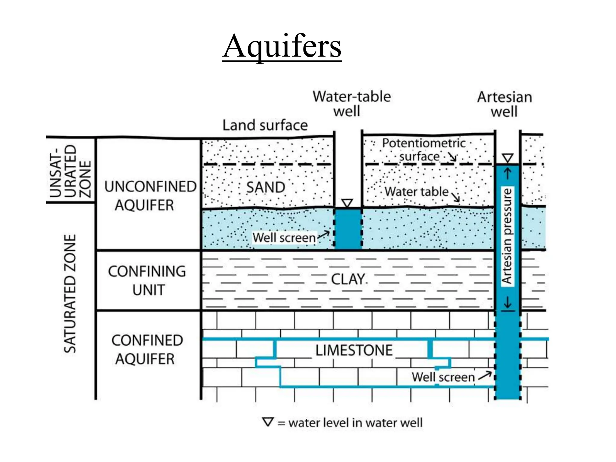
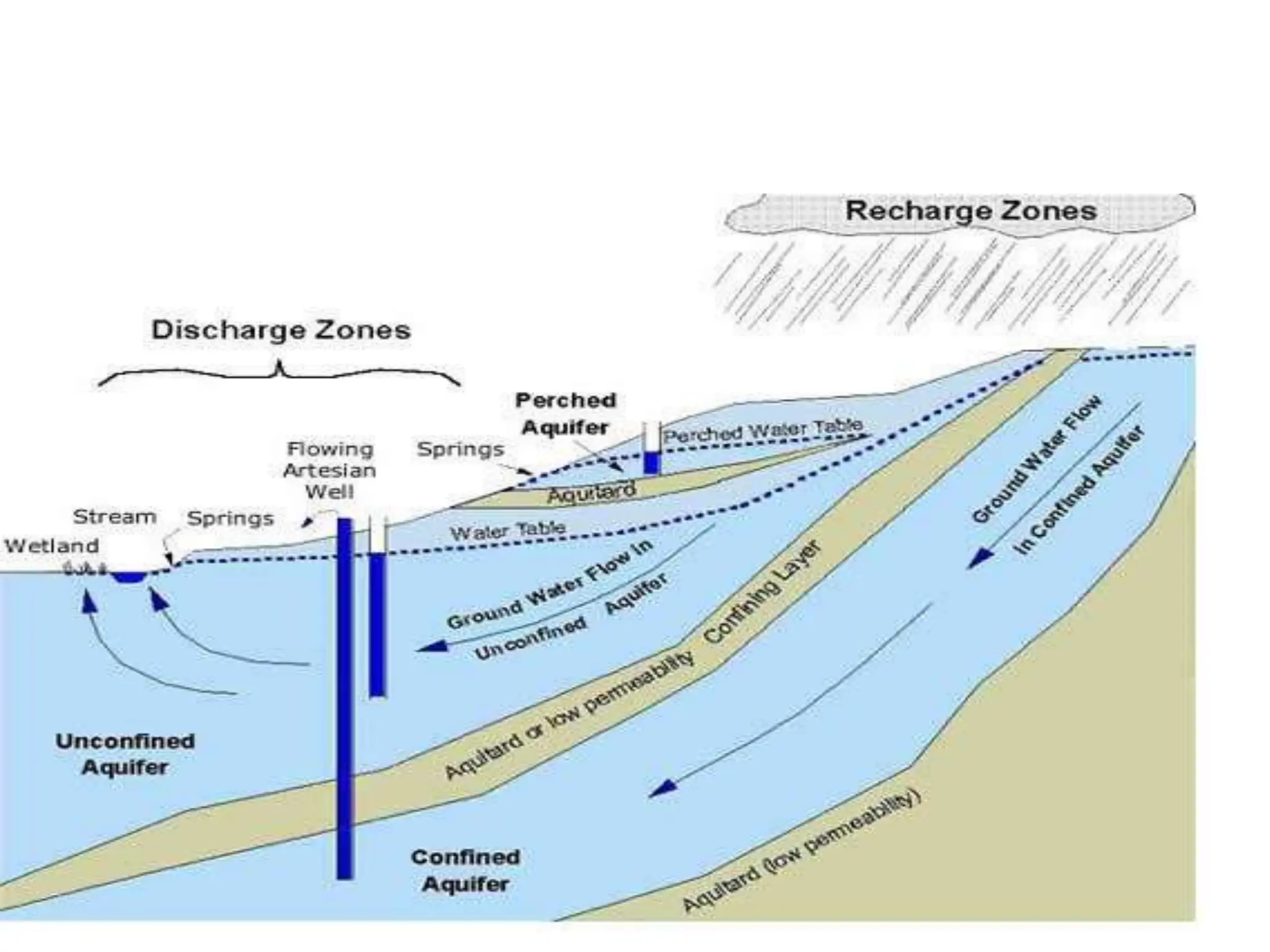
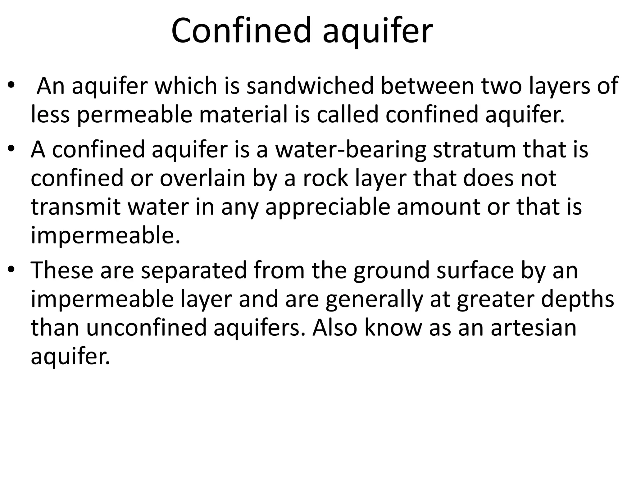
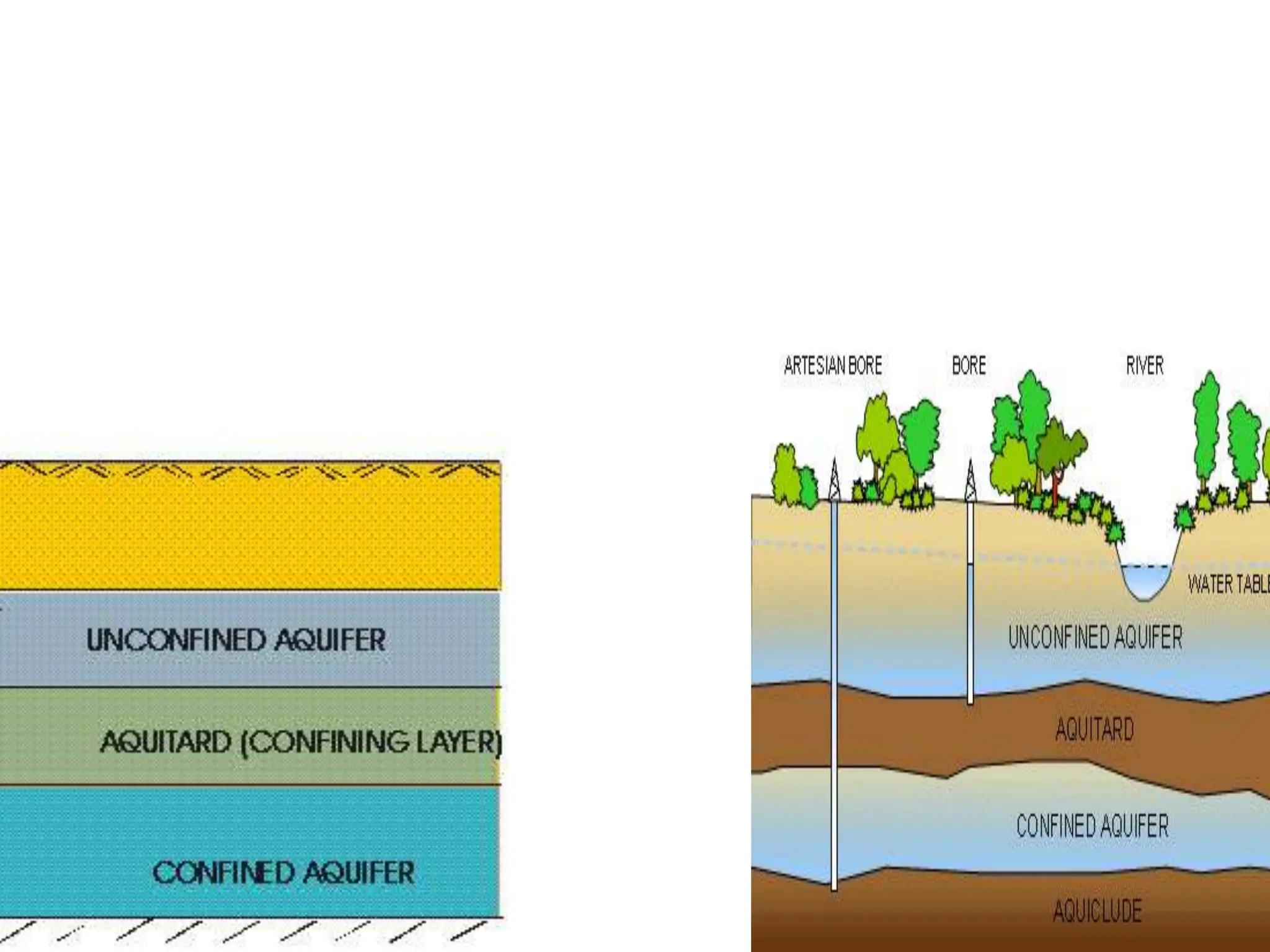
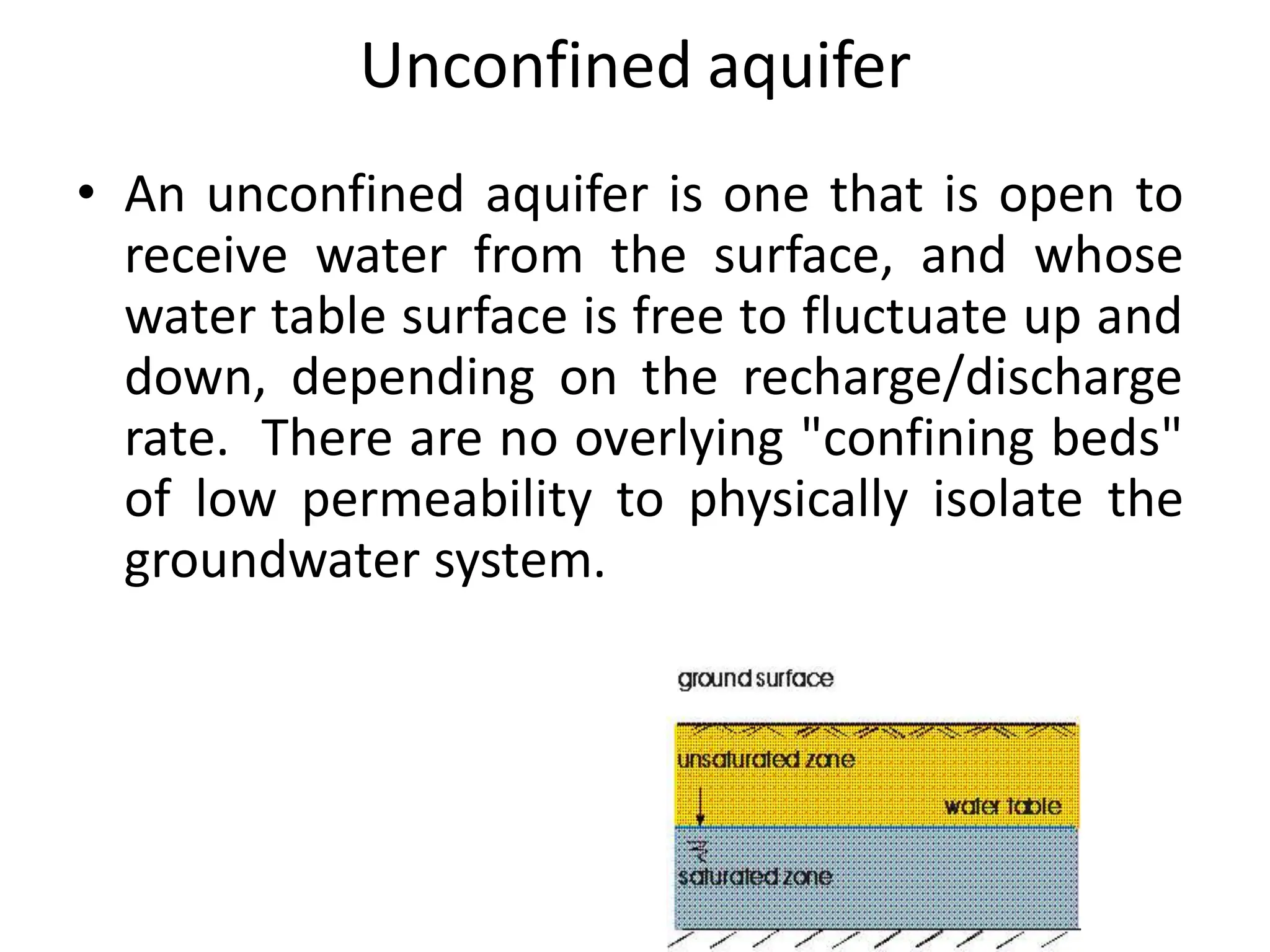
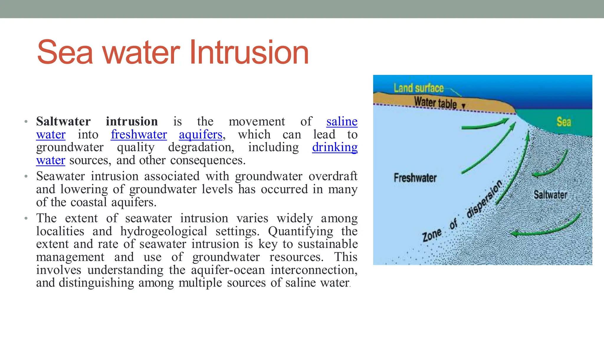
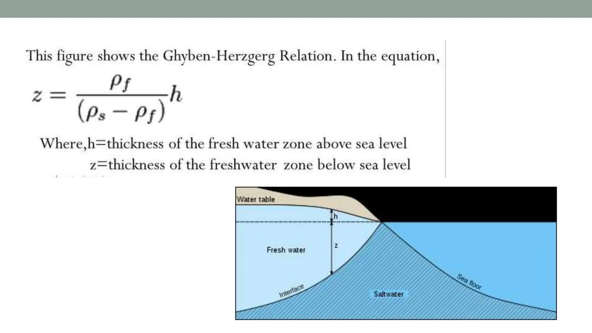
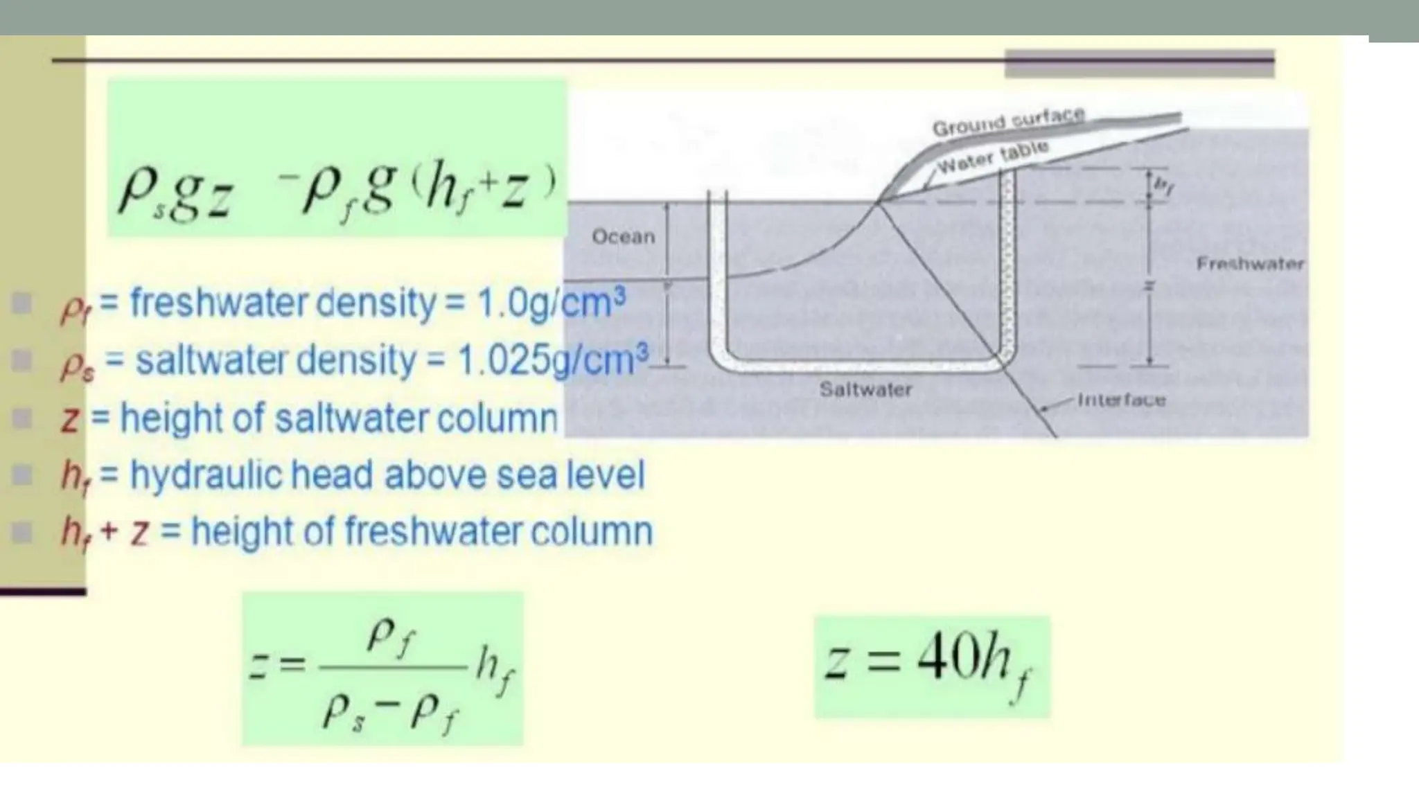
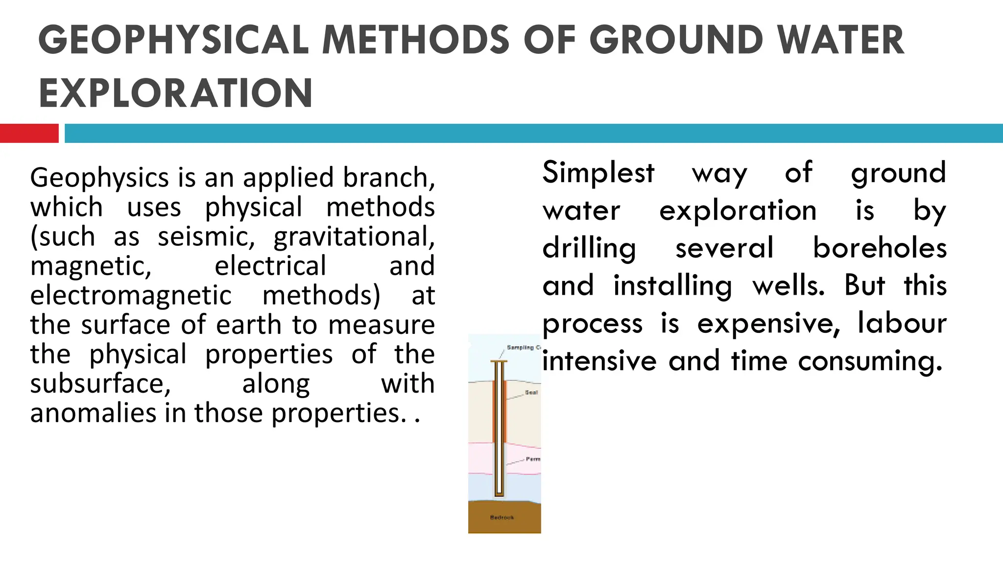
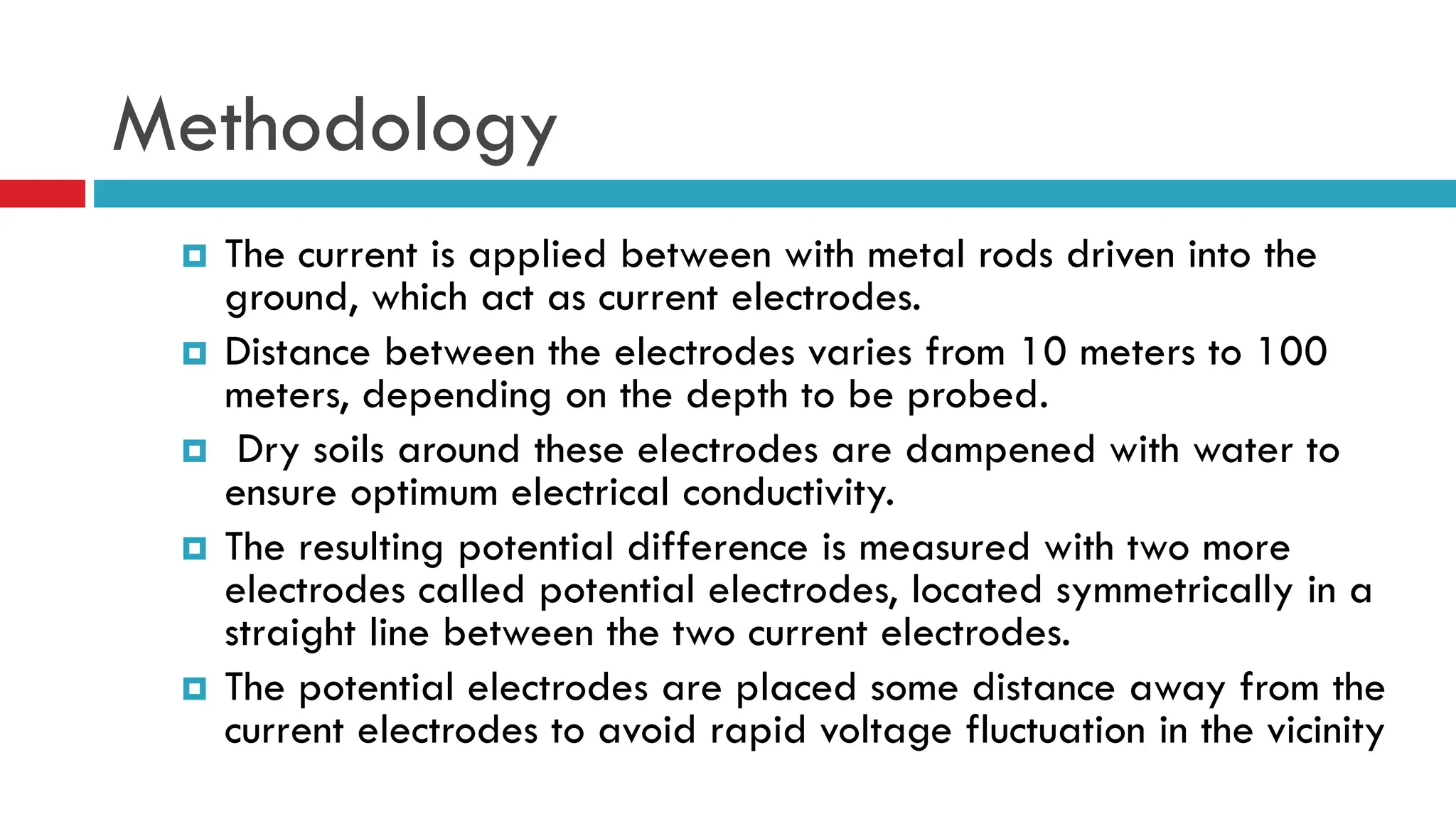
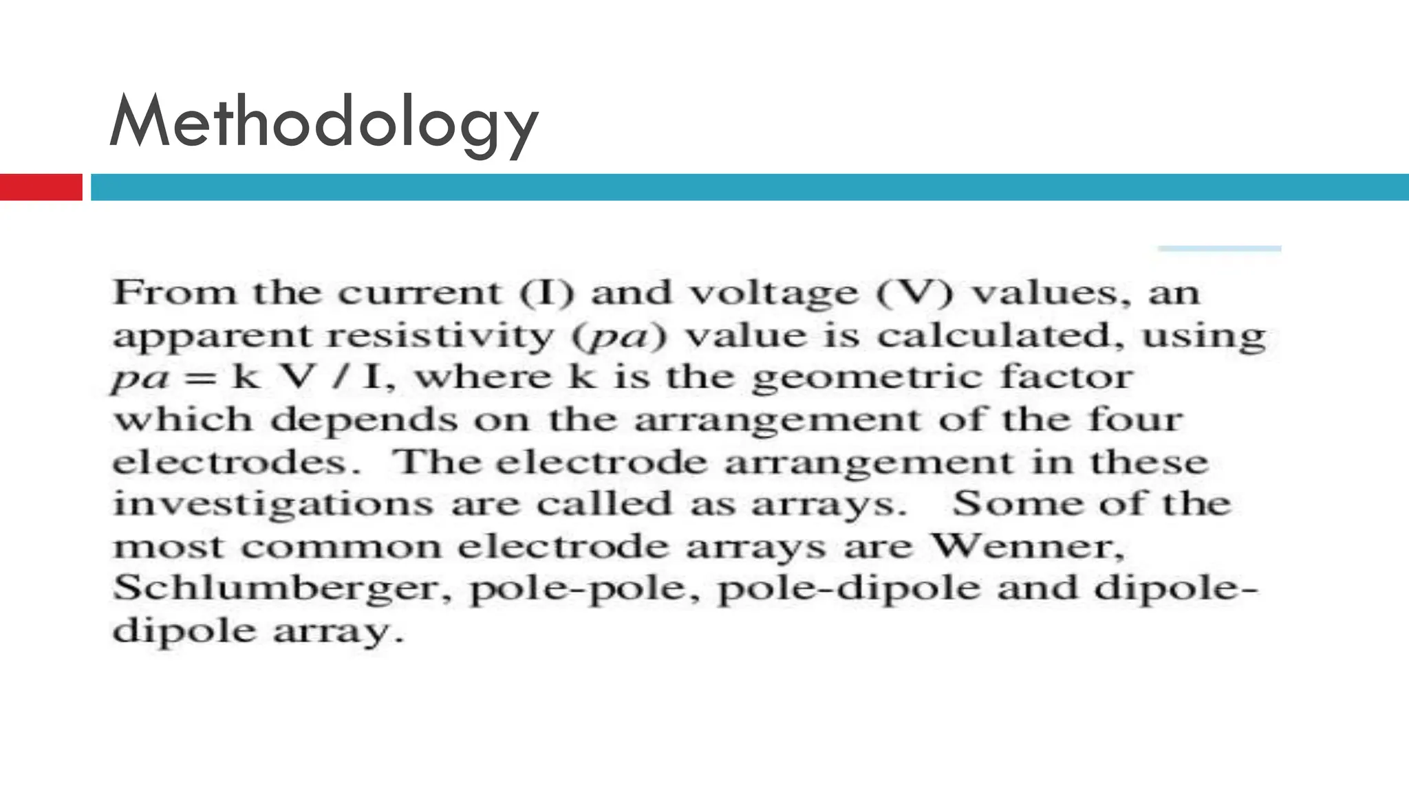
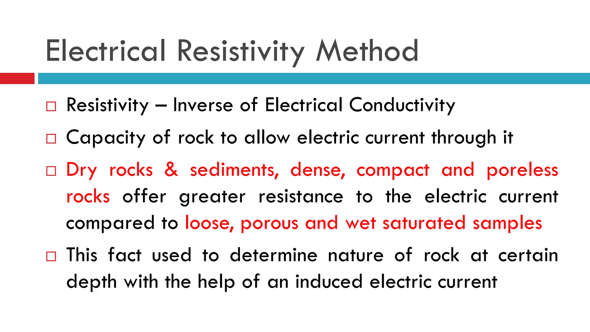
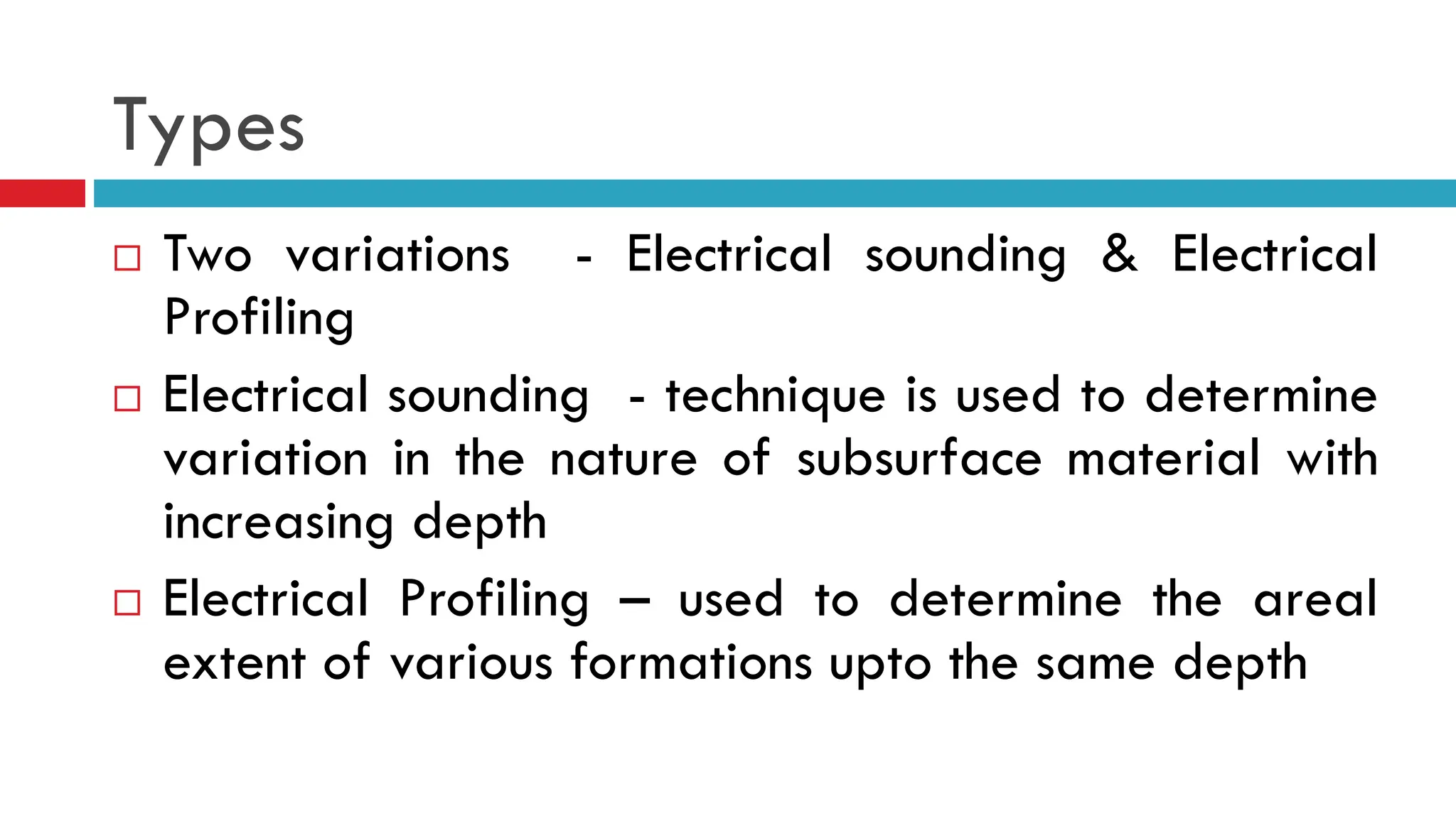
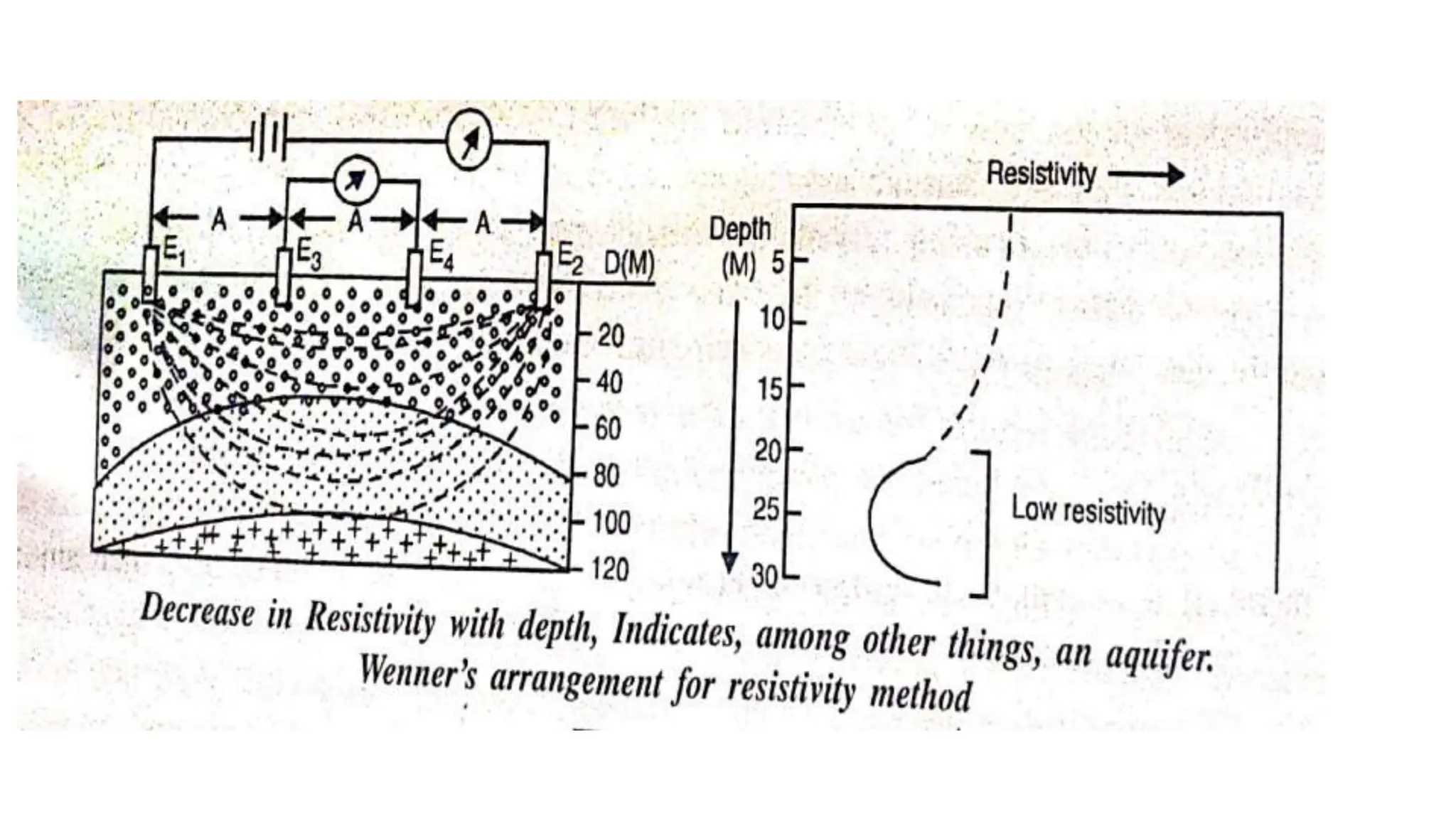
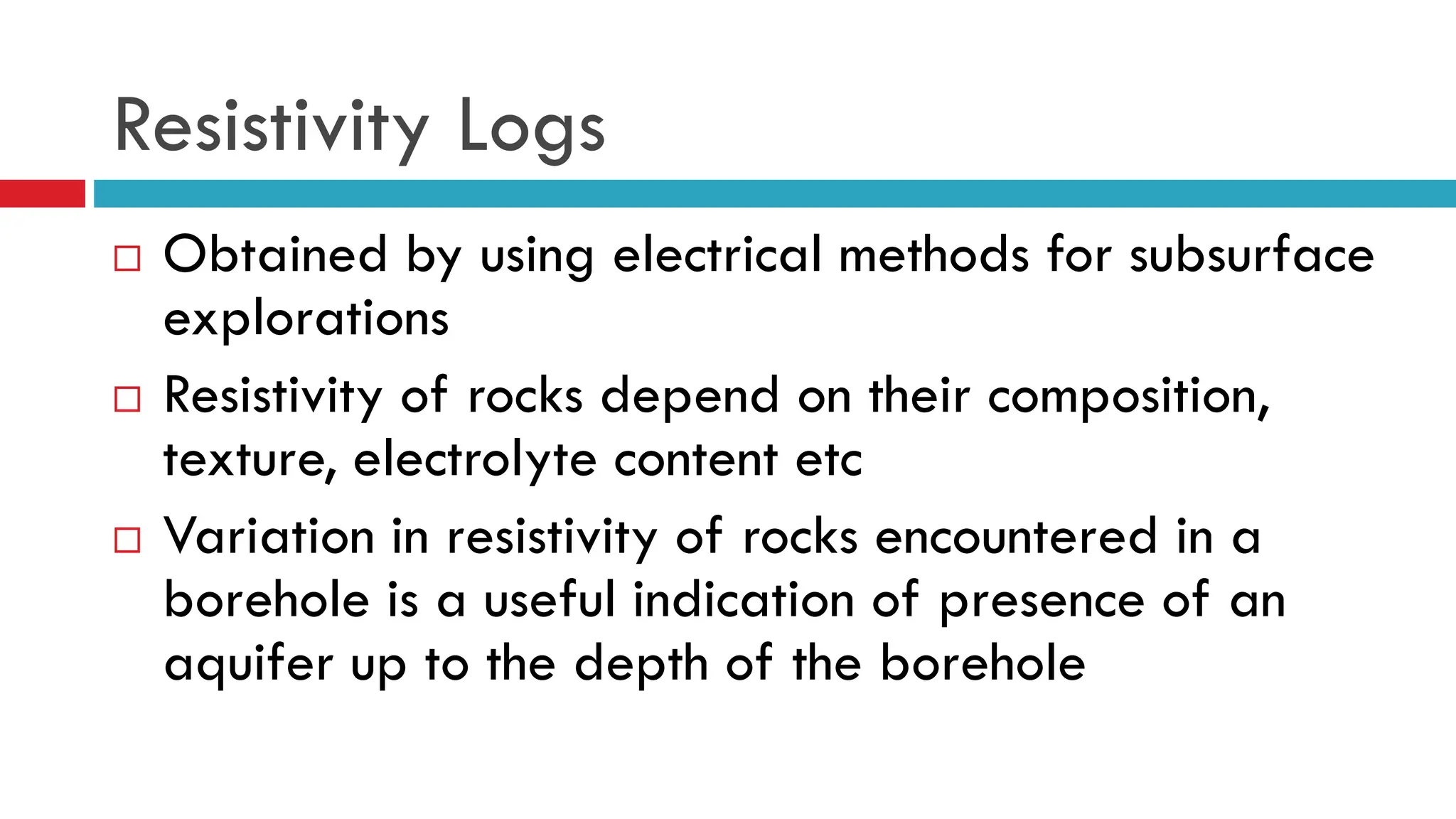
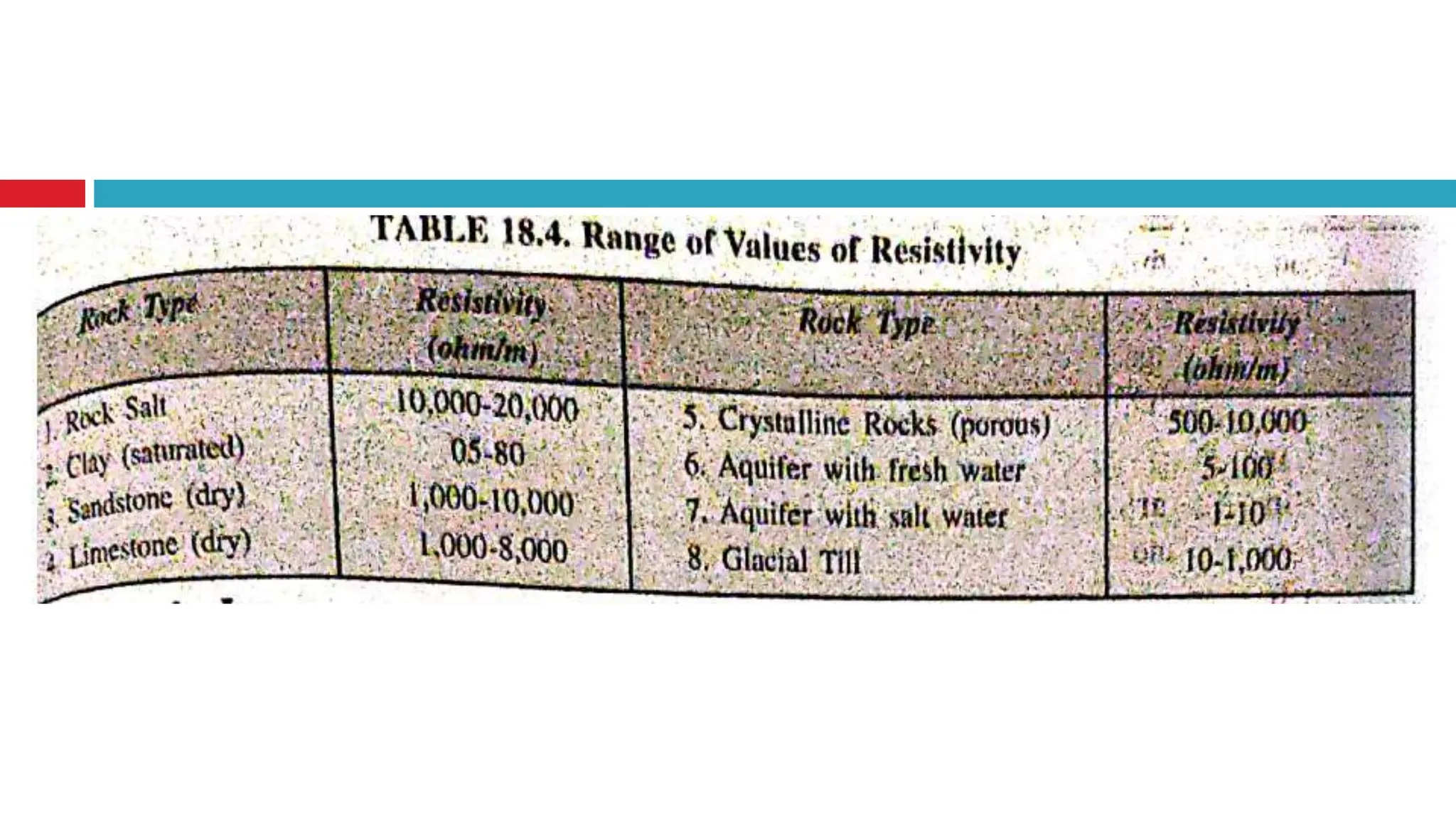
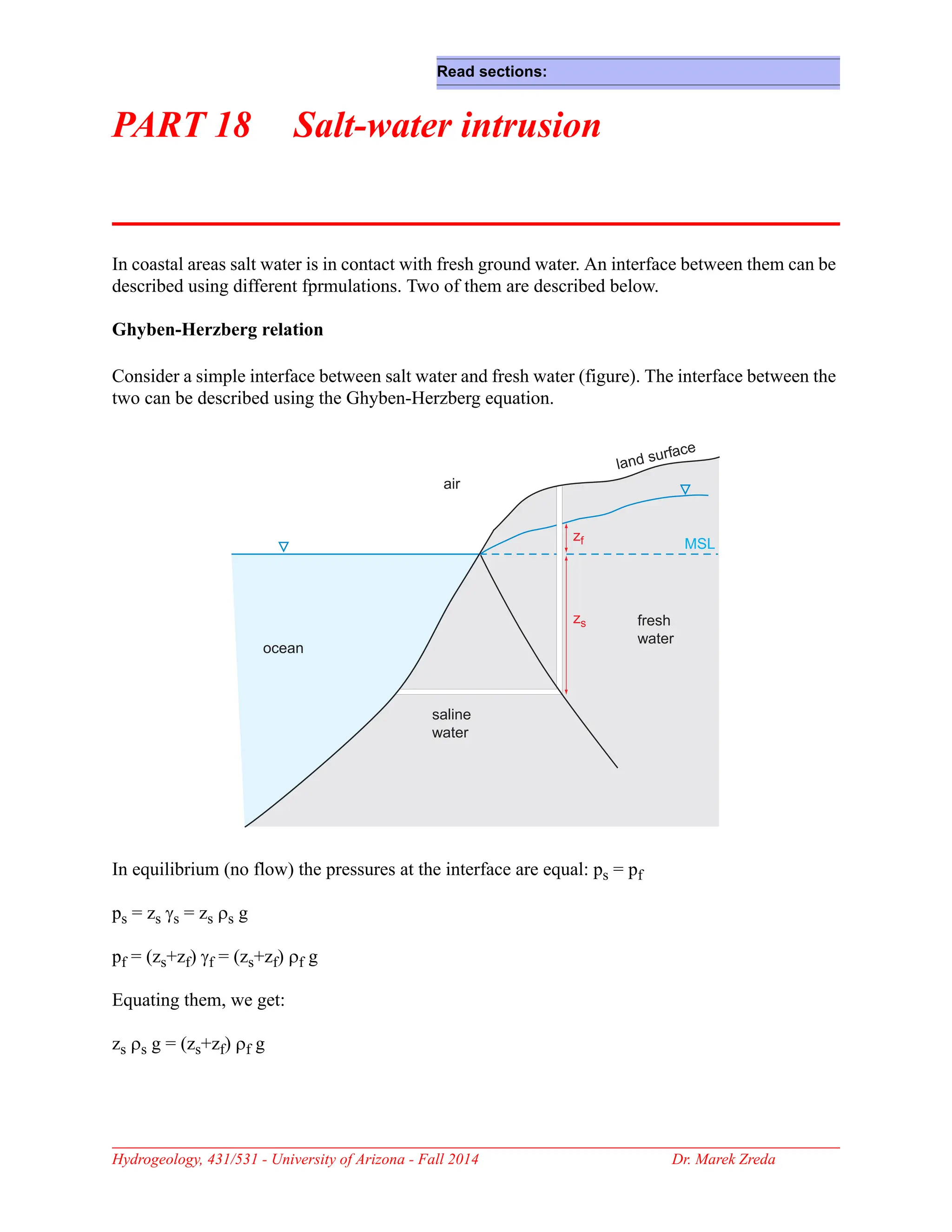
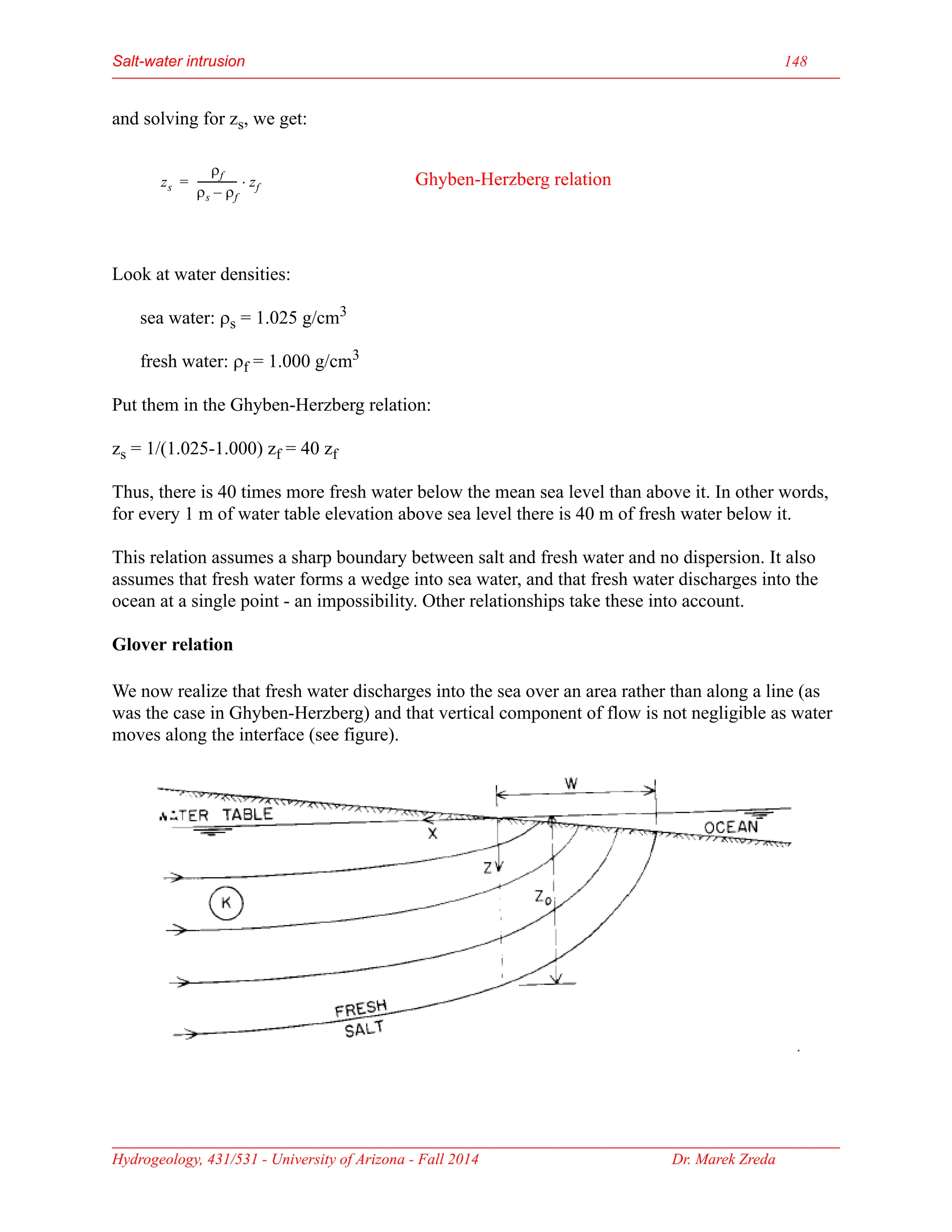
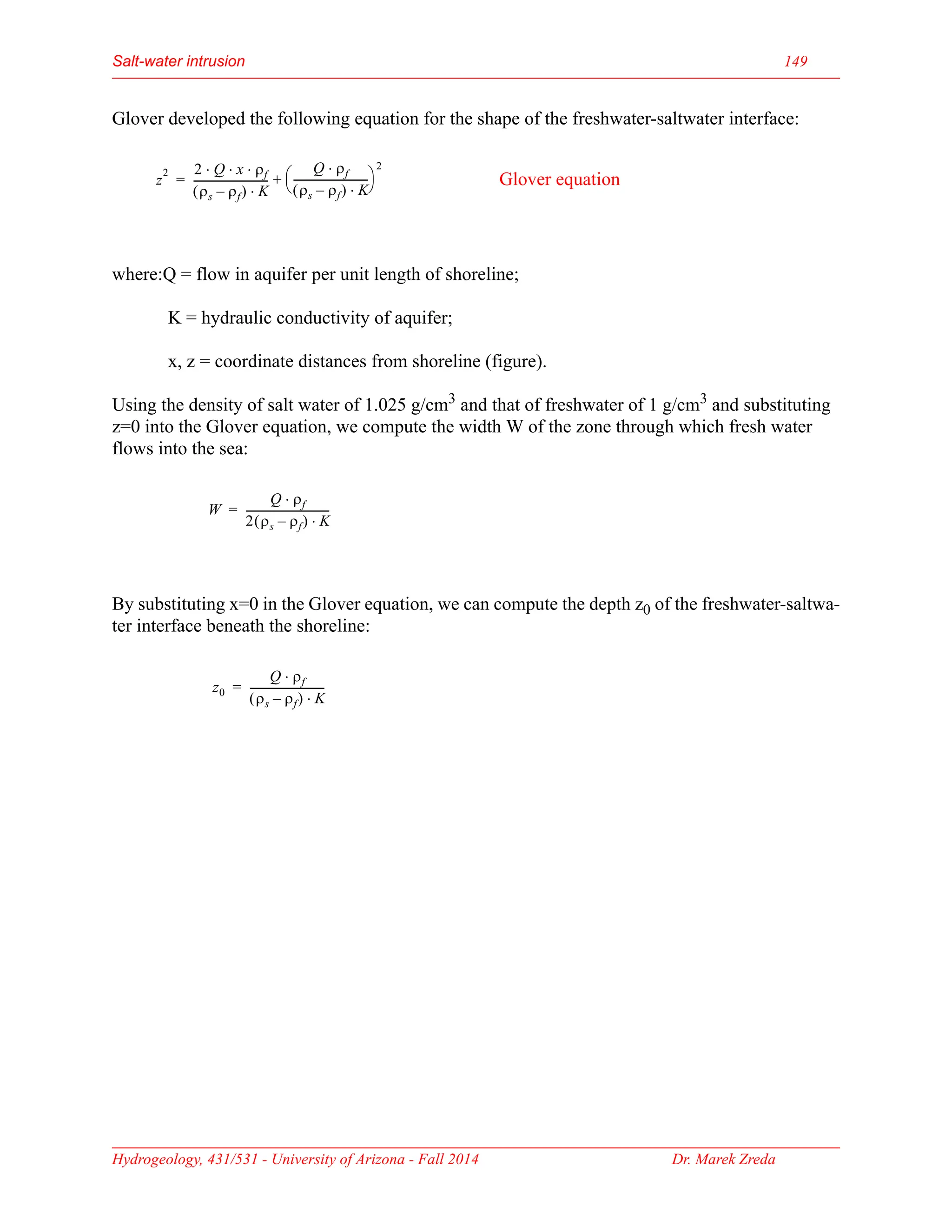
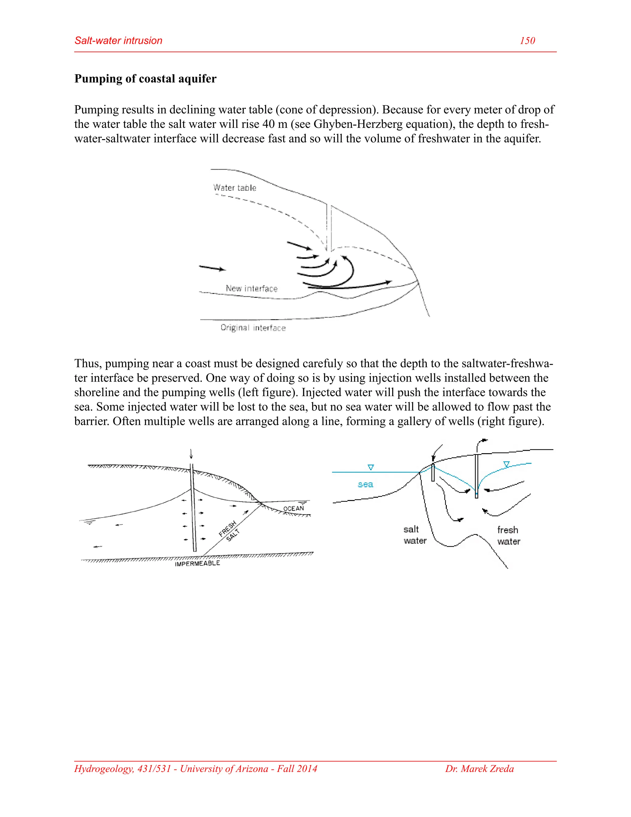
Groundwater is the largest source of freshwater on Earth, existing in saturated soil and rock formations known as aquifers, which can be confined or unconfined. Specific properties of aquifers, such as porosity, permeability, and transmissivity, impact their ability to store and yield water. Geophysical methods, including electrical resistivity, are used for groundwater exploration, and the Ghyben-Herzberg and Glover relations help understand saltwater intrusion in coastal areas due to changes in aquifer pressure and pumping practices.