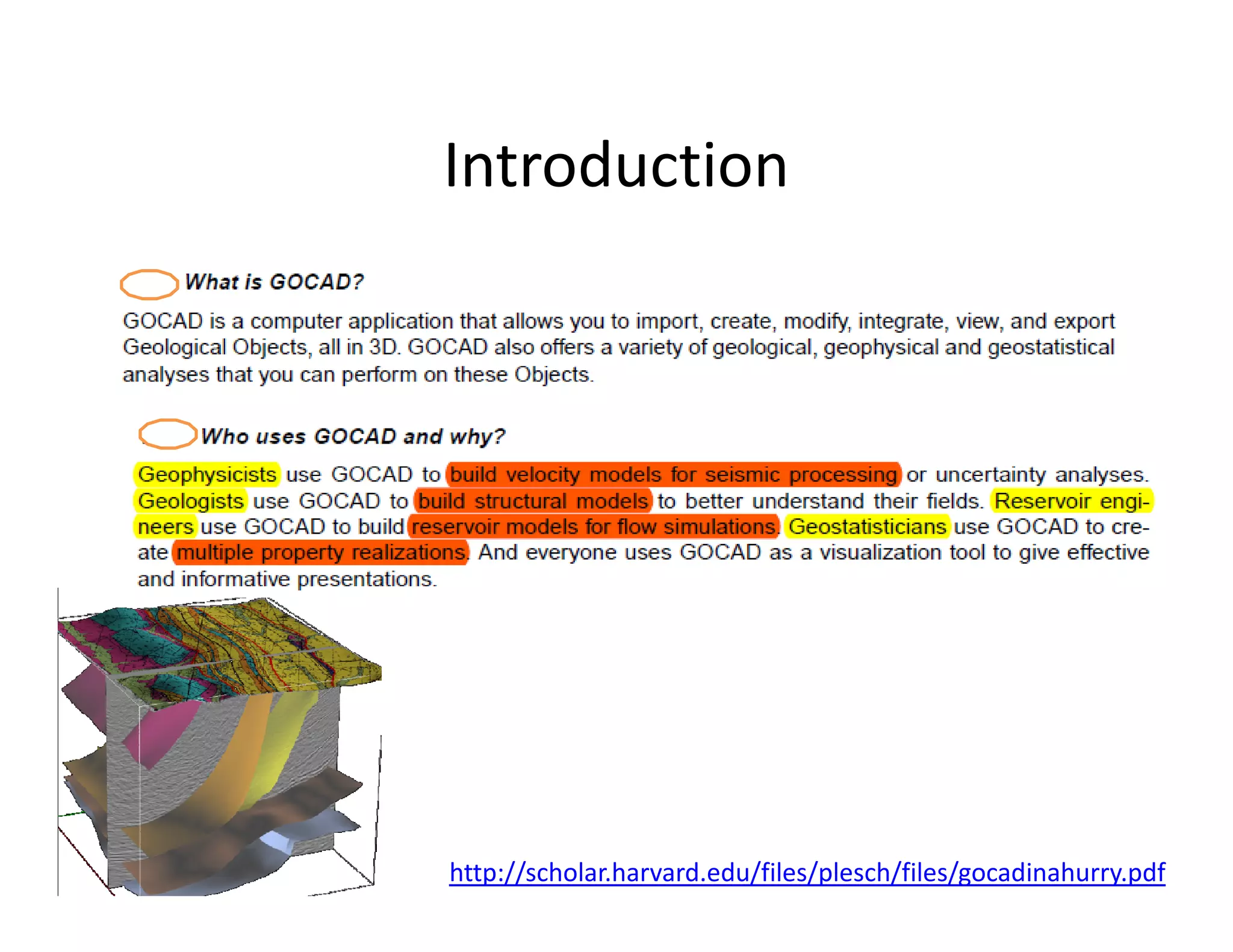
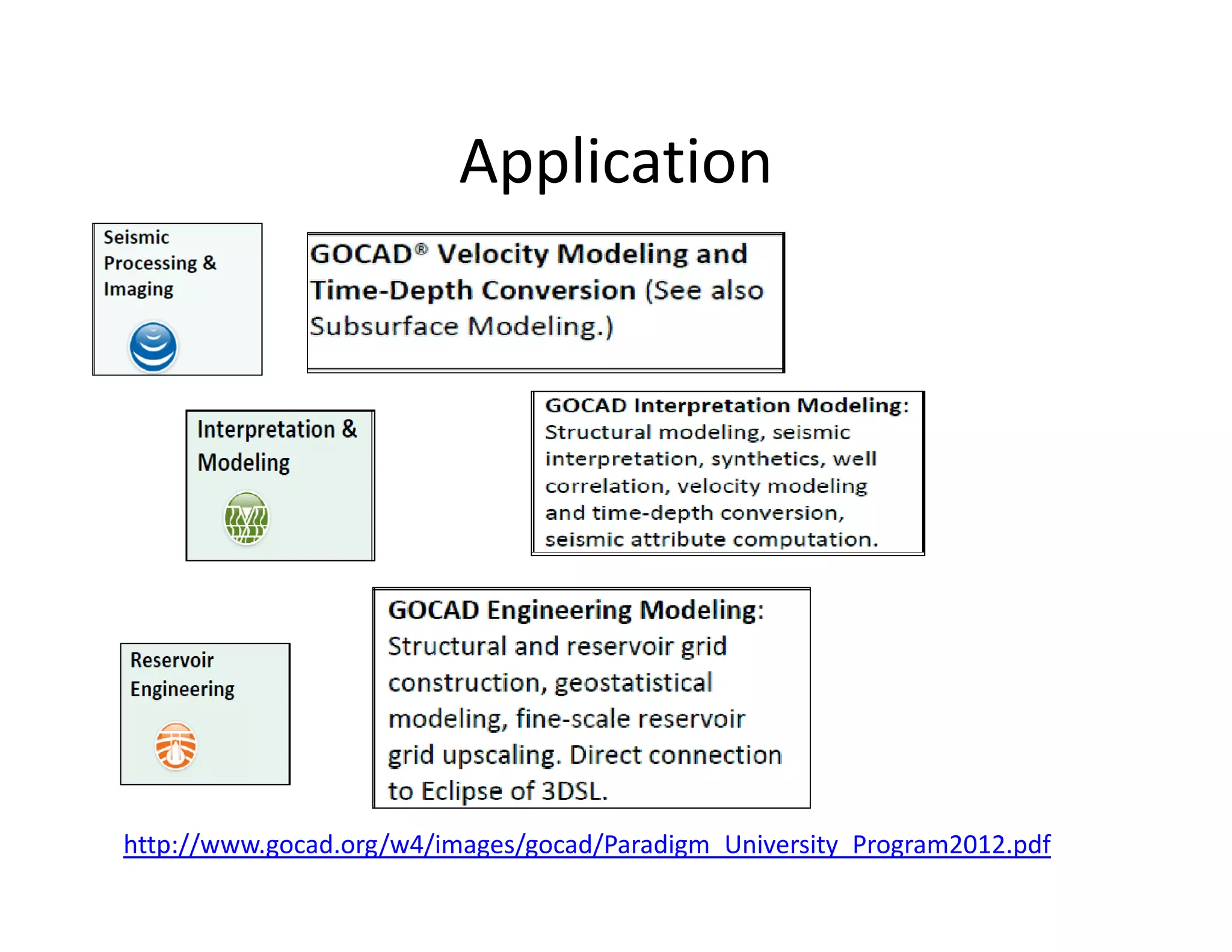
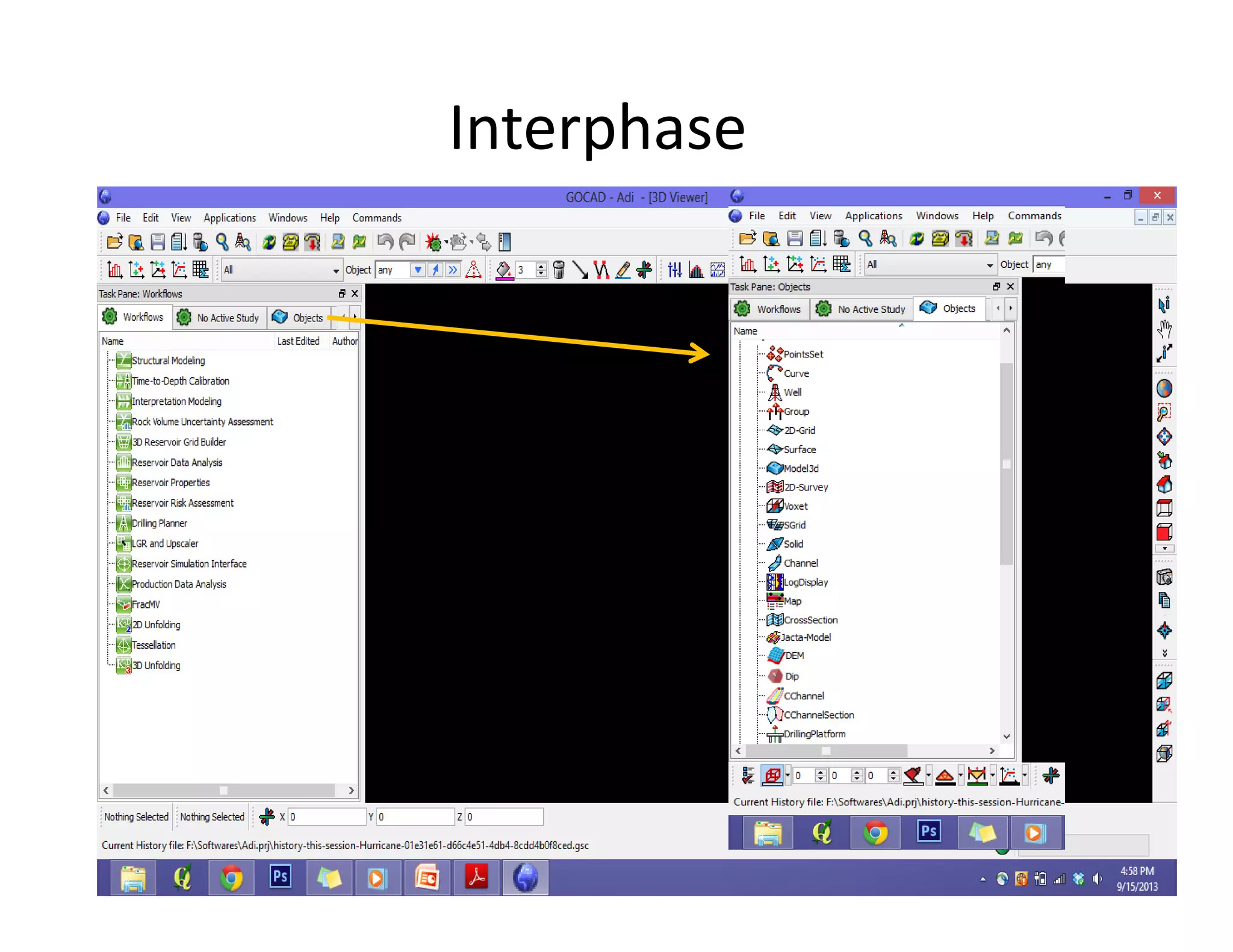
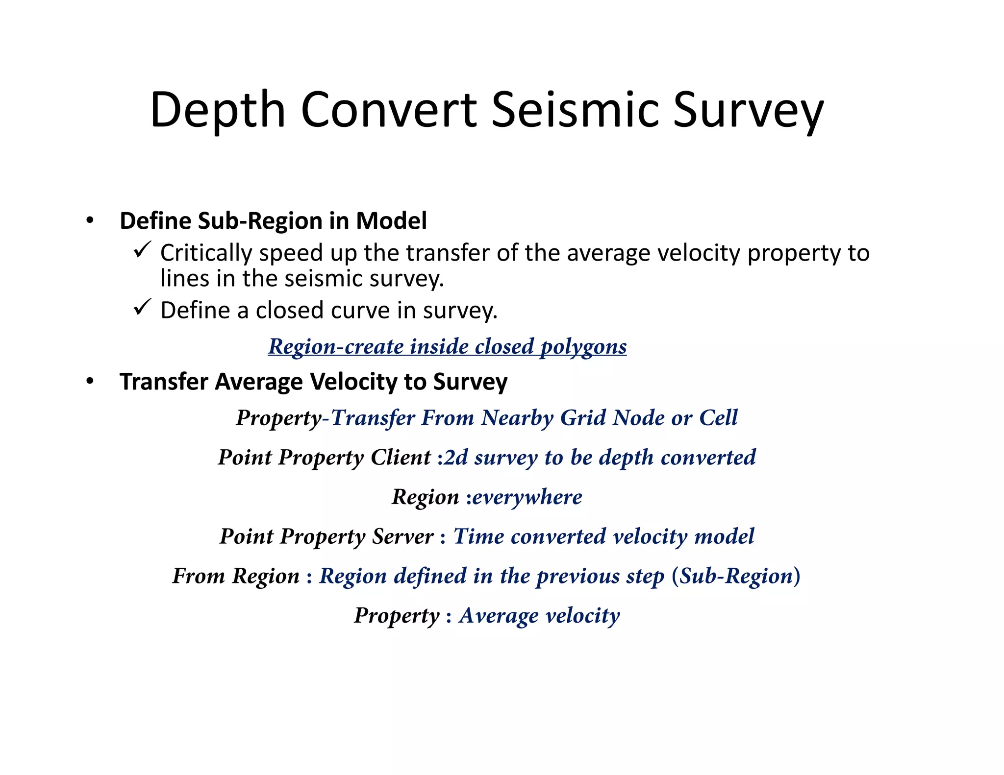
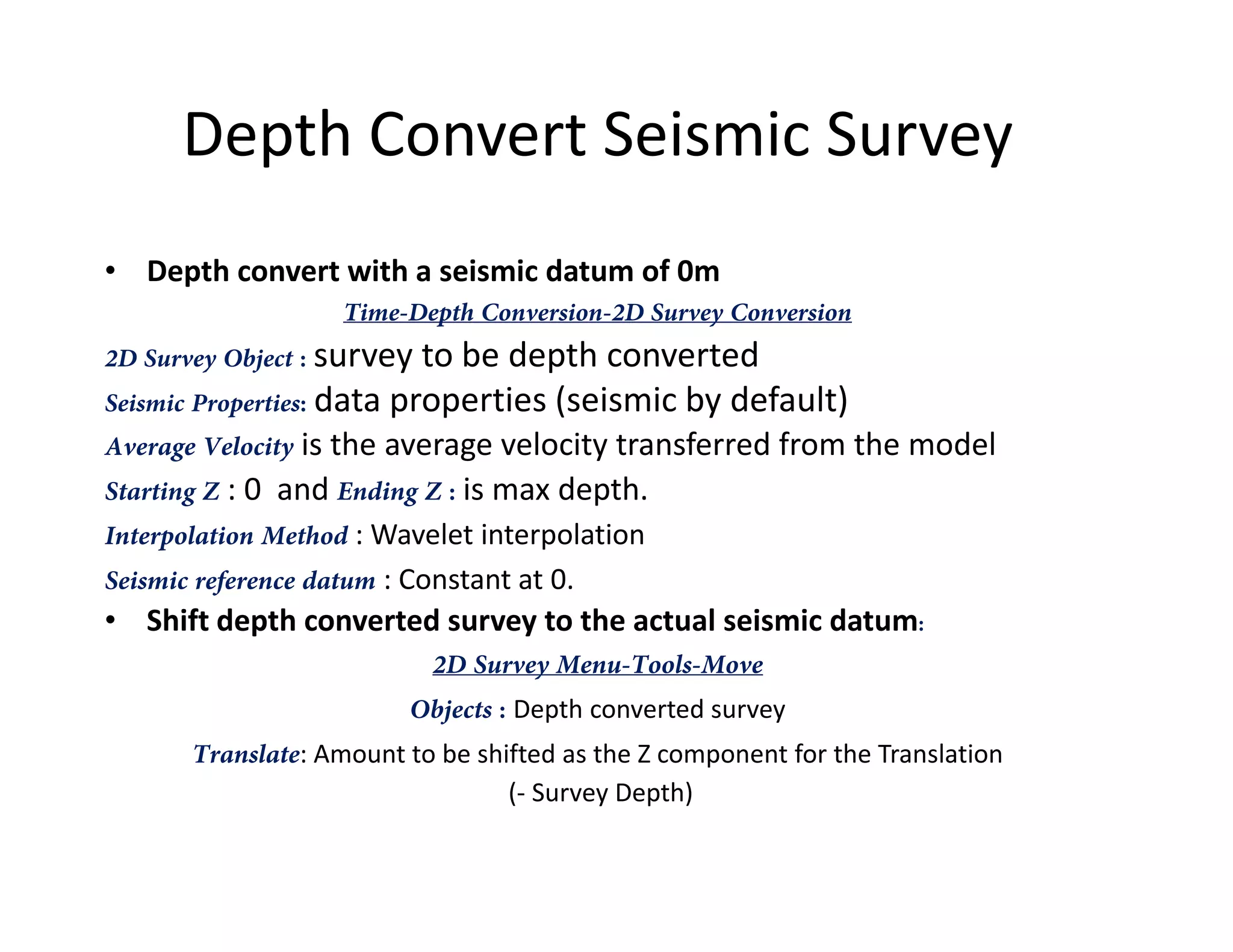
GOCAD
Aditya Tiwari
Introduction
http://scholar.harvard.edu/files/plesch/files/gocadinahurry.pdf
Application
http://www.gocad.org/w4/images/gocad/Paradigm_University_Program2012.pdf
Interphase
File Format
http://tu-freiberg.de/fakult3/gy/mageo/lehre_3d/vorlesung/script_uebung.pdf
Features
http://scholar.harvard.edu/files/plesch/files/gocadinahurry.pdf
Features
Stores Co-ordinates and add scalar /vector properties. Input Data: Sampling points
with orientation, Geochemical or Petro physical properties or locations for terrain
modeling.
Point Sets:
File - Import Objects - Horizon/Fault
Interpretations – PointsSet – Column-based File
..
Features
Region:
PointsSet - Region – Create PointsSet - Region -
Initialize From Property Range
Script:
Available on right click on Properties.
Allows to write small logical operations :
Example: Define Sw
Sw=1-sqrt (30/(resistivity*pow(porosity,2)));
Features
Curves:
Curves are often used to import 2d pre-interpreted data like geological maps and proles, or to
digitize data, like seismic reflectors, in Gocad.
File - Load Objects "CurveDigi.mx“
Object Panel - Objects - Curve - From Digitized Polyline
Edit:
Curve mode - Tools -Curve mode - Tools -
Node
Connect:
Curve - Tools - Node –
Bridge
Merge
Curve - New - From
Curves - Curves
Features
Surfaces:
Represent geological boundaries, like faults and bedding planes.Commonly they
are created by interpolating input data like Points Sets, Wells or Curves.
Surface -New From several curves -Name:cross section-ok-press Ctrl-key and keep
pressed-pick the curve objects profil1 and profil 2 in the 3D camera -leave Ctrl-key
1.
• New Surface with Direct Triangulation
Surface - New - From Several Curves
• nb of levels: how many triangle strips will be inserted between the
copied nodes of the Curve Parts,
• low value would result in very narrow triangles and rough surface
Surface - Tools - Beautify - Beautify Triangles
Smoothens the surface
Features
2.
• New Surface with Discrete Smooth Interpolation (DSI)
DSI method allows to smoothly interpolating Properties while taking into account
Constraints
Surface - New - From Points Set Medium Plane
The new plane Surface consists of only two triangles; we need to discretize
appropriately in order to fit data,
Surface - Tools - Split All Apply +Apply +Apply +OKSurface - Tools - Split All Apply +Apply +Apply +OK
Set the nodes of the All Curves as Control Points.
Surface - Constraints - Control Points - Set Control Points
Set a Constraint on the Border which fixes the Border nodes in the XY plane
Surface - Constraints- Constraints on Borders - Set On Straight Lines – All Borders
Interpolation
Surface - Interpolation - Geometry - On Entire Surface – Apply
Compute Thickness
Surface - Compute - Compute Vertical Thickness
Features
EXAMPLE: Import wells with a marker point sandstone_top and set it as an additional
constraint
File - Load Objects
Well markers cannot be set as Control Points directly.
Convert the Well markers to a Points Set.
3.
• Adapting a Surface to Honor Well or Point Data
PointsSet - New From Well - Well Markers
Surface - Constraints - Control Points - Set Control Points
Surface - Interpolation - Geometry - On Entire Surface
Surface - Constraints - Control Nodes - Set - From Control Points (Select top of sandstone)
Surface - Tools - Beautify - Beautify Triangles for Equilaterality
Surface - Tools – Node/Triangles
Modelling Fault
Steps:
Data import and data preparation, image georeferencing, and data
integration with DSI
From a set of wells, outcrop points with fault azimut/dip measurements, and a 2D
seismic section.
Create two conjugate normal faults master Fault and northFault.
(Shown in Figure)(Shown in Figure)
Import of Elevation Points and Outcrop Sampling Points
File - Import Objects - Horizon Interpretations - X Y Z
Velocity
Model
Velocity Model
Prepare velocity model:
Smoothing and replacement of infill
velocities
Extend to expected seismic datum of survey
Time convert velocity model using itself:
Shift top to 0
Calculate average velocity
Use linear interpolation at conversion
Prepare time converted velocity model:
http://scholar.harvard.edu/plesch/pages/depth-conversion-pdgm-gocad
Prepare time converted velocity model:
Recalculate average velocity in time
converted velocity model
Requires replacement of any no-data values
with infill velocity
Depth convert seismic survey:
Define sub-region in model;
Transfer average velocity to seismic survey as
additional property
Depth conversion.
Prepare velocity model:
• Smoothing
Severely smooth an existing velocity model to avoid any ungeologic features
being introduced by the depth conversion
Compute-Apply Median/Average Filter
Filter will replace the no-data with average values. But need to experiment with
window size. Because if model is fast and small window is not selected average
velocity increases.velocity increases.
Remove very high velocities with no data values
• Replace Infill Velocity
For offshore surveys the seismic velocity of water is often used (1480 m/s).
For Onshore the elevation where travel time in the processed seismic is set to
0ms is considered below ground surface.
Refer : http://scholar.harvard.edu/plesch/pages/depth-conversion-pdgm-gocad for details
on infill velocity in case seismic data includes data above ground level.
Prepare velocity model:
• Truncate/Extend to Seismic Datum
Top of the velocity model should be at the same elevation as the seismic
datum of the seismic survey to be depth converted.
GOCAD depth conversion function offers arbitrary seismic datum but is
inconsistent.
Well tops can help to estimate seismic datum if their position is known inWell tops can help to estimate seismic datum if their position is known in
time and depth
If the ground level in the seismic data can be identified, its elevation can
be looked up from a DEM
Convenient to use New-Extracted from Voxet to crop the velocity
model such that its top is identical to the seismic datum
Time Convert Velocity Model
• Shift Top to 0
Use Tools-Resize Voxet with Vectors and provide a new Z
value for the origin which will then shift the voxet to proper amount.
• Calculate Average Velocity
Convert Velocity Type: In One DomainConvert Velocity Type: In One Domain
Input Velocity is the smoothed and filled interval velocity of the
model
Input Velocity Type : Depth Interval
Unit is m/s (one way time)
Output velocity : Named vave,
Output Velocity Type : Depth Average
Visually quality check: Property should be smooth and increase in
value downwards (Generally)
Time Convert Velocity Model
• Convert model in time domain.
Time-Depth Conversion-Convert Seismic Cube
Voxet Seismic is the prepared velocity model voxet
Seismic Properties : Original interval velocity smoothed and filled
velocity and the calculated average velocity (vave).
Pick Depth to Time Conversion
Voxet Velocity Cube : Pick the prepared velocity model voxet
Average Velocity is v , and associated Velocity Unit m/s is (two wayAverage Velocity is vave , and associated Velocity Unit m/s is (two way
time because desired output should be in two way time)
Output Voxet Name can be time VelMod
Starting Z should be 0 and the Ending Z as high as the deepest level of the
seismic survey to be depth convert in milliseconds
Number of Depth/Time Steps : sufficiently high to capture the velocity
model structure
Choose linear interpolation as Interpolation Method, not wavelet
interpolation which is used for seismic data and not velocity data.
Seismic Reference Datum needs to be set as Constant and at 0.
Prepare Time Converted Velocity
Model
• Replace no-data values
Applied to the time converted model when the process is
not able to map corresponding depth data
if (v_int_smooth_filled < 0){v_int_smooth_filled = XXXX;}
• Recalculate Average Velocity
The result (v_ave_t) should be very similar to the average
velocity calculated in the depth domain (v_ave) but
without no-data values
Depth Convert Seismic Survey
• Define Sub-Region in Model
Critically speed up the transfer of the average velocity property to
lines in the seismic survey.
Define a closed curve in survey.
Region-create inside closed polygons
• Transfer Average Velocity to Survey• Transfer Average Velocity to Survey
Property-Transfer From Nearby Grid Node or Cell
Point Property Client :2d survey to be depth converted
Region :everywhere
Point Property Server : Time converted velocity model
From Region : Region defined in the previous step (Sub-Region)
Property : Average velocity
Depth Convert Seismic Survey
• Depth convert with a seismic datum of 0m
Time-Depth Conversion-2D Survey Conversion
2D Survey Object : survey to be depth converted
Seismic Properties: data properties (seismic by default)
Average Velocity is the average velocity transferred from the model
Starting Z : 0 and Ending Z : is max depth.Starting Z : 0 and Ending Z : is max depth.
Interpolation Method : Wavelet interpolation
Seismic reference datum : Constant at 0.
• Shift depth converted survey to the actual seismic datum:
2D Survey Menu-Tools-Move
Objects : Depth converted survey
Translate: Amount to be shifted as the Z component for the Translation
(- Survey Depth)
References (Web Links)
• http://paulbourke.net/dataformats/gocad/gocad.pdf
• http://tu-freiberg.de/fakult3/gy/mageo/lehre_3d/vorlesung/script_uebung.pdf
• http://scholar.harvard.edu/plesch/pages/depth-conversion-pdgm-gocad
• http://www.geol.agh.edu.pl/~dwornik/mtex/Gocad_Tutorial.pdf
• http://www.gocad.org/w4/index.php/gocad/presentation
• http://scholar.harvard.edu/files/plesch/files/gocadinahurry.pdf
Other Useful Links:
http://sepwww.stanford.edu/public/docs/sep80/bob/paper_html/
• http://www.pdgm.com/getattachment/Resources/Brochures/SKUA-Structure-and-
Stratigraphy/SKUA-Stratigraphy.pdf.aspx

Gocad Tutorial

  • 1.
  • 2.
  • 3.
  • 4.
  • 5.
  • 6.
  • 7.
    Features Stores Co-ordinates andadd scalar /vector properties. Input Data: Sampling points with orientation, Geochemical or Petro physical properties or locations for terrain modeling. Point Sets: File - Import Objects - Horizon/Fault Interpretations – PointsSet – Column-based File ..
  • 8.
    Features Region: PointsSet - Region– Create PointsSet - Region - Initialize From Property Range Script: Available on right click on Properties. Allows to write small logical operations : Example: Define Sw Sw=1-sqrt (30/(resistivity*pow(porosity,2)));
  • 9.
    Features Curves: Curves are oftenused to import 2d pre-interpreted data like geological maps and proles, or to digitize data, like seismic reflectors, in Gocad. File - Load Objects "CurveDigi.mx“ Object Panel - Objects - Curve - From Digitized Polyline Edit: Curve mode - Tools -Curve mode - Tools - Node Connect: Curve - Tools - Node – Bridge Merge Curve - New - From Curves - Curves
  • 10.
    Features Surfaces: Represent geological boundaries,like faults and bedding planes.Commonly they are created by interpolating input data like Points Sets, Wells or Curves. Surface -New From several curves -Name:cross section-ok-press Ctrl-key and keep pressed-pick the curve objects profil1 and profil 2 in the 3D camera -leave Ctrl-key 1. • New Surface with Direct Triangulation Surface - New - From Several Curves • nb of levels: how many triangle strips will be inserted between the copied nodes of the Curve Parts, • low value would result in very narrow triangles and rough surface Surface - Tools - Beautify - Beautify Triangles Smoothens the surface
  • 11.
    Features 2. • New Surfacewith Discrete Smooth Interpolation (DSI) DSI method allows to smoothly interpolating Properties while taking into account Constraints Surface - New - From Points Set Medium Plane The new plane Surface consists of only two triangles; we need to discretize appropriately in order to fit data, Surface - Tools - Split All Apply +Apply +Apply +OKSurface - Tools - Split All Apply +Apply +Apply +OK Set the nodes of the All Curves as Control Points. Surface - Constraints - Control Points - Set Control Points Set a Constraint on the Border which fixes the Border nodes in the XY plane Surface - Constraints- Constraints on Borders - Set On Straight Lines – All Borders Interpolation Surface - Interpolation - Geometry - On Entire Surface – Apply Compute Thickness Surface - Compute - Compute Vertical Thickness
  • 12.
    Features EXAMPLE: Import wellswith a marker point sandstone_top and set it as an additional constraint File - Load Objects Well markers cannot be set as Control Points directly. Convert the Well markers to a Points Set. 3. • Adapting a Surface to Honor Well or Point Data PointsSet - New From Well - Well Markers Surface - Constraints - Control Points - Set Control Points Surface - Interpolation - Geometry - On Entire Surface Surface - Constraints - Control Nodes - Set - From Control Points (Select top of sandstone) Surface - Tools - Beautify - Beautify Triangles for Equilaterality Surface - Tools – Node/Triangles
  • 13.
    Modelling Fault Steps: Data importand data preparation, image georeferencing, and data integration with DSI From a set of wells, outcrop points with fault azimut/dip measurements, and a 2D seismic section. Create two conjugate normal faults master Fault and northFault. (Shown in Figure)(Shown in Figure) Import of Elevation Points and Outcrop Sampling Points File - Import Objects - Horizon Interpretations - X Y Z
  • 14.
  • 15.
    Velocity Model Prepare velocitymodel: Smoothing and replacement of infill velocities Extend to expected seismic datum of survey Time convert velocity model using itself: Shift top to 0 Calculate average velocity Use linear interpolation at conversion Prepare time converted velocity model: http://scholar.harvard.edu/plesch/pages/depth-conversion-pdgm-gocad Prepare time converted velocity model: Recalculate average velocity in time converted velocity model Requires replacement of any no-data values with infill velocity Depth convert seismic survey: Define sub-region in model; Transfer average velocity to seismic survey as additional property Depth conversion.
  • 16.
    Prepare velocity model: •Smoothing Severely smooth an existing velocity model to avoid any ungeologic features being introduced by the depth conversion Compute-Apply Median/Average Filter Filter will replace the no-data with average values. But need to experiment with window size. Because if model is fast and small window is not selected average velocity increases.velocity increases. Remove very high velocities with no data values • Replace Infill Velocity For offshore surveys the seismic velocity of water is often used (1480 m/s). For Onshore the elevation where travel time in the processed seismic is set to 0ms is considered below ground surface. Refer : http://scholar.harvard.edu/plesch/pages/depth-conversion-pdgm-gocad for details on infill velocity in case seismic data includes data above ground level.
  • 17.
    Prepare velocity model: •Truncate/Extend to Seismic Datum Top of the velocity model should be at the same elevation as the seismic datum of the seismic survey to be depth converted. GOCAD depth conversion function offers arbitrary seismic datum but is inconsistent. Well tops can help to estimate seismic datum if their position is known inWell tops can help to estimate seismic datum if their position is known in time and depth If the ground level in the seismic data can be identified, its elevation can be looked up from a DEM Convenient to use New-Extracted from Voxet to crop the velocity model such that its top is identical to the seismic datum
  • 18.
    Time Convert VelocityModel • Shift Top to 0 Use Tools-Resize Voxet with Vectors and provide a new Z value for the origin which will then shift the voxet to proper amount. • Calculate Average Velocity Convert Velocity Type: In One DomainConvert Velocity Type: In One Domain Input Velocity is the smoothed and filled interval velocity of the model Input Velocity Type : Depth Interval Unit is m/s (one way time) Output velocity : Named vave, Output Velocity Type : Depth Average Visually quality check: Property should be smooth and increase in value downwards (Generally)
  • 19.
    Time Convert VelocityModel • Convert model in time domain. Time-Depth Conversion-Convert Seismic Cube Voxet Seismic is the prepared velocity model voxet Seismic Properties : Original interval velocity smoothed and filled velocity and the calculated average velocity (vave). Pick Depth to Time Conversion Voxet Velocity Cube : Pick the prepared velocity model voxet Average Velocity is v , and associated Velocity Unit m/s is (two wayAverage Velocity is vave , and associated Velocity Unit m/s is (two way time because desired output should be in two way time) Output Voxet Name can be time VelMod Starting Z should be 0 and the Ending Z as high as the deepest level of the seismic survey to be depth convert in milliseconds Number of Depth/Time Steps : sufficiently high to capture the velocity model structure Choose linear interpolation as Interpolation Method, not wavelet interpolation which is used for seismic data and not velocity data. Seismic Reference Datum needs to be set as Constant and at 0.
  • 20.
    Prepare Time ConvertedVelocity Model • Replace no-data values Applied to the time converted model when the process is not able to map corresponding depth data if (v_int_smooth_filled < 0){v_int_smooth_filled = XXXX;} • Recalculate Average Velocity The result (v_ave_t) should be very similar to the average velocity calculated in the depth domain (v_ave) but without no-data values
  • 21.
    Depth Convert SeismicSurvey • Define Sub-Region in Model Critically speed up the transfer of the average velocity property to lines in the seismic survey. Define a closed curve in survey. Region-create inside closed polygons • Transfer Average Velocity to Survey• Transfer Average Velocity to Survey Property-Transfer From Nearby Grid Node or Cell Point Property Client :2d survey to be depth converted Region :everywhere Point Property Server : Time converted velocity model From Region : Region defined in the previous step (Sub-Region) Property : Average velocity
  • 22.
    Depth Convert SeismicSurvey • Depth convert with a seismic datum of 0m Time-Depth Conversion-2D Survey Conversion 2D Survey Object : survey to be depth converted Seismic Properties: data properties (seismic by default) Average Velocity is the average velocity transferred from the model Starting Z : 0 and Ending Z : is max depth.Starting Z : 0 and Ending Z : is max depth. Interpolation Method : Wavelet interpolation Seismic reference datum : Constant at 0. • Shift depth converted survey to the actual seismic datum: 2D Survey Menu-Tools-Move Objects : Depth converted survey Translate: Amount to be shifted as the Z component for the Translation (- Survey Depth)
  • 23.
    References (Web Links) •http://paulbourke.net/dataformats/gocad/gocad.pdf • http://tu-freiberg.de/fakult3/gy/mageo/lehre_3d/vorlesung/script_uebung.pdf • http://scholar.harvard.edu/plesch/pages/depth-conversion-pdgm-gocad • http://www.geol.agh.edu.pl/~dwornik/mtex/Gocad_Tutorial.pdf • http://www.gocad.org/w4/index.php/gocad/presentation • http://scholar.harvard.edu/files/plesch/files/gocadinahurry.pdf Other Useful Links: http://sepwww.stanford.edu/public/docs/sep80/bob/paper_html/ • http://www.pdgm.com/getattachment/Resources/Brochures/SKUA-Structure-and- Stratigraphy/SKUA-Stratigraphy.pdf.aspx