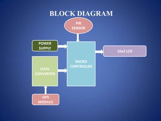
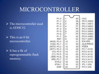
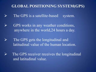
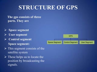
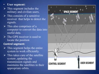
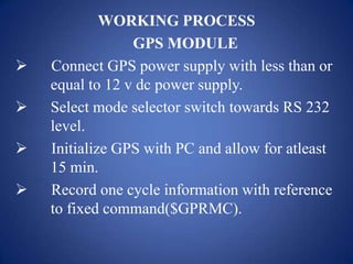
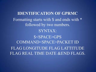
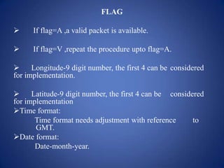
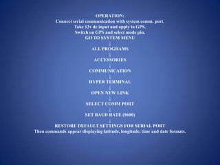
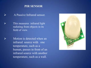
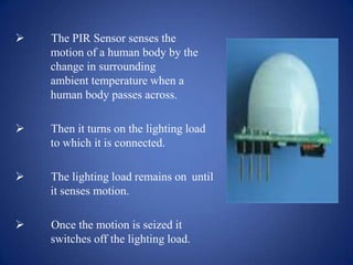
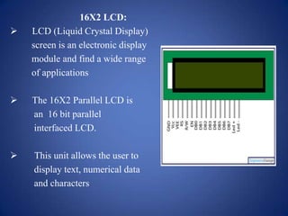
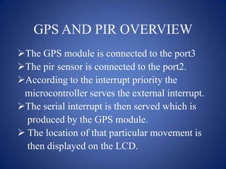
GPS TRACKING WITH
PIR APPLICATION
AIM OF THE PROJECT
This project intends us to geotag a
particular location in accordance with
movement detection by using GPS module
and PIR sensor respectively.
BLOCK DIAGRAM
PIR
SENSOR
POWER
SUPPLY
16x2 LCD
LEVEL
CONVERTER
GPS
MODULE
MICRO
CONTROLLER
DESCRIPTION
The project deals with a GPS module and a
PIR sensor.
The GPS module is a satellite based system
and tracks the location of the objects.
The PIR sensor is an infrared radiation based
sensor .
It detects the movement of the objects within a
radius of 5m.
MICROCONTROLLER
 The microcontroller used
is AT89C52.
 This is an 8 bit
microcontroller.
 It has a 8k of
reprogrammable flash
memory.
GLOBAL POSITIONING SYSTEM(GPS)
 The GPS is a satellite-based system.
 GPS works in any weather conditions,
anywhere in the world,24 hours a day.
 The GPS gets the longitudinal and
latitudinal value of the human location.
 The GPS receiver receives the longitudinal
and latitudinal value.
STRUCTURE OF GPS
The gps consists of three
parts. They are
 Space segment
 User segment
 Control segment
Space segment:
 This segment consists of the
satellite system
 These helps us to locate the
position by broadcasting the
signals.
Space Segment Control Segment User Segment
GPS
• User segment:
 This segment includes the
military and civilian users.
 This consists of a sensitive
receiver that helps to detect the
signals.
 This also comprises of a
computer to convert the data into
useful data.
 The GPS receiver is used to
locate the position
Control segment:
 This segment helps the entire
system to work efficiently.
 This takes care of the satellite
system ,updating the
transmission signals and
maintains the satellites in their
appropriate orbits.
WORKING PROCESS
GPS MODULE
 Connect GPS power supply with less than or
equal to 12 v dc power supply.
 Select mode selector switch towards RS 232
level.
 Initialize GPS with PC and allow for atleast
15 min.
 Record one cycle information with reference
to fixed command($GPRMC).
IDENTIFICATION OF GPRMC
Formatting starts with $ and ends with *
followed by two numbers.
SYNTAX:
$<SPACE>GPS
COMMAND<SPACE>PACKET ID
FLAG LONGITUDE FLAG LATTITUDE
FLAG REAL TIME DATE &END FLAGS.
FLAG
 If flag=A ,a valid packet is available.
 If flag=V ,repeat the procedure upto flag=A.
 Longitude-9 digit number, the first 4 can be considered
for implementation.
 Latitude-9 digit number, the first 4 can be considered
for implementation
Time format:
Time format needs adjustment with reference to
GMT.
Date format:
Date-month-year.
OPERATION:
Connect serial communication with system comm. port.
Take 12v dc input and apply to GPS.
Switch on GPS and select mode pin.
GO TO SYSTEM MENU
↓
ALL PROGRAMS
↓
ACCESSORIES
↓
COMMUNICATION
↓
HYPER TERMINAL
↓
OPEN NEW LINK
↓
SELECT COMM PORT
↓
SET BAUD RATE (9600)
↓
RESTORE DEFAULT SETTINGS FOR SERIAL PORT
Then commands appear displaying latitude, longitude, time and date formats.
PIR SENSOR
 A Passive Infrared sensor.
 This measures infrared light
radiating from objects in its
field of view.
 Motion is detected when an
infrared source with one
temperature, such as a
human, passes in front of an
infrared source with another
temperature, such as a wall.
 The PIR Sensor senses the
motion of a human body by the
change in surrounding
ambient temperature when a
human body passes across.
 Then it turns on the lighting load
to which it is connected.
 The lighting load remains on until
it senses motion.
 Once the motion is seized it
switches off the lighting load.
GEOTAGGING THE MOVEMENT
 Initialize GPS.
 Initialize embedded board.
 Connect PIR sensor towards main module
and reset the system.
 Connect GPS receiver and reset the system.
 For movement observation allow object to
move less than 5m with 120 degrees
viewing angle with respect to PIR base.
 Notice movement along with GPS data and
identification of places.
16X2 LCD:
 LCD (Liquid Crystal Display)
screen is an electronic display
module and find a wide range
of applications
 The 16X2 Parallel LCD is
an 16 bit parallel
interfaced LCD.
 This unit allows the user to
display text, numerical data
and characters
POWER SUPPLY
 230vAc mains are stepped down by
transformer.
 The transformer output is rectified by a
full-wave bridge rectifier.
 The capacitors used in the circuit bypass the
ripples present in the regulated power supply.
GPS AND PIR OVERVIEW
The GPS module is connected to the port3
The pir sensor is connected to the port2.
According to the interrupt priority the
microcontroller serves the external interrupt.
The serial interrupt is then served which is
produced by the GPS module.
 The location of that particular movement is
then displayed on the LCD.
ADVANTAGES
 Very easy installation.
 No separate wiring is required hence no
additional installation cost.
 PIR sensors are generally compact and can be
fitted into virtually any electronic device.
 They do not need an external power
source because they generate electricity as
they absorb infrared light.
LIMITATIONS
PIR sensors can only receive infrared light and
cannot emit it like other types of infrared
sensors.
 They can be expensive to purchase,
install, and calibrate as well.
APPLICATIONS
This project is widely applicable in
 Prohibited areas.
 Archeological surveys.
 Detection of unauthorized entries in the
border security.
 Navigation.
 Burglar alarm control panels.
 Home security systems.
FUTURE SCOPE
This project has it’s advancements in areas of
 Army
 Automobiles
 Aircraft
 Navy
 Archeological surveys
CONCLUSION
 The technology of the Global Positioning
System is allowing for huge changes in
society.
 More reliable and accurate measurements.
 Less costly to corporations - since the
error removing equipment will no longer be
needed.
 More affordable and accessible to
consumers.
 Greater incentive for the development of
new uses.
THANK YOU

Global positioning system

  • 1.
  • 2.
    AIM OF THEPROJECT This project intends us to geotag a particular location in accordance with movement detection by using GPS module and PIR sensor respectively.
  • 3.
  • 4.
    DESCRIPTION The project dealswith a GPS module and a PIR sensor. The GPS module is a satellite based system and tracks the location of the objects. The PIR sensor is an infrared radiation based sensor . It detects the movement of the objects within a radius of 5m.
  • 5.
    MICROCONTROLLER  The microcontrollerused is AT89C52.  This is an 8 bit microcontroller.  It has a 8k of reprogrammable flash memory.
  • 6.
    GLOBAL POSITIONING SYSTEM(GPS) The GPS is a satellite-based system.  GPS works in any weather conditions, anywhere in the world,24 hours a day.  The GPS gets the longitudinal and latitudinal value of the human location.  The GPS receiver receives the longitudinal and latitudinal value.
  • 7.
    STRUCTURE OF GPS Thegps consists of three parts. They are  Space segment  User segment  Control segment Space segment:  This segment consists of the satellite system  These helps us to locate the position by broadcasting the signals. Space Segment Control Segment User Segment GPS
  • 8.
    • User segment: This segment includes the military and civilian users.  This consists of a sensitive receiver that helps to detect the signals.  This also comprises of a computer to convert the data into useful data.  The GPS receiver is used to locate the position Control segment:  This segment helps the entire system to work efficiently.  This takes care of the satellite system ,updating the transmission signals and maintains the satellites in their appropriate orbits.
  • 9.
    WORKING PROCESS GPS MODULE Connect GPS power supply with less than or equal to 12 v dc power supply.  Select mode selector switch towards RS 232 level.  Initialize GPS with PC and allow for atleast 15 min.  Record one cycle information with reference to fixed command($GPRMC).
  • 10.
    IDENTIFICATION OF GPRMC Formattingstarts with $ and ends with * followed by two numbers. SYNTAX: $<SPACE>GPS COMMAND<SPACE>PACKET ID FLAG LONGITUDE FLAG LATTITUDE FLAG REAL TIME DATE &END FLAGS.
  • 11.
    FLAG  If flag=A,a valid packet is available.  If flag=V ,repeat the procedure upto flag=A.  Longitude-9 digit number, the first 4 can be considered for implementation.  Latitude-9 digit number, the first 4 can be considered for implementation Time format: Time format needs adjustment with reference to GMT. Date format: Date-month-year.
  • 12.
    OPERATION: Connect serial communicationwith system comm. port. Take 12v dc input and apply to GPS. Switch on GPS and select mode pin. GO TO SYSTEM MENU ↓ ALL PROGRAMS ↓ ACCESSORIES ↓ COMMUNICATION ↓ HYPER TERMINAL ↓ OPEN NEW LINK ↓ SELECT COMM PORT ↓ SET BAUD RATE (9600) ↓ RESTORE DEFAULT SETTINGS FOR SERIAL PORT Then commands appear displaying latitude, longitude, time and date formats.
  • 13.
    PIR SENSOR  APassive Infrared sensor.  This measures infrared light radiating from objects in its field of view.  Motion is detected when an infrared source with one temperature, such as a human, passes in front of an infrared source with another temperature, such as a wall.
  • 14.
     The PIRSensor senses the motion of a human body by the change in surrounding ambient temperature when a human body passes across.  Then it turns on the lighting load to which it is connected.  The lighting load remains on until it senses motion.  Once the motion is seized it switches off the lighting load.
  • 15.
    GEOTAGGING THE MOVEMENT Initialize GPS.  Initialize embedded board.  Connect PIR sensor towards main module and reset the system.  Connect GPS receiver and reset the system.  For movement observation allow object to move less than 5m with 120 degrees viewing angle with respect to PIR base.  Notice movement along with GPS data and identification of places.
  • 16.
    16X2 LCD:  LCD(Liquid Crystal Display) screen is an electronic display module and find a wide range of applications  The 16X2 Parallel LCD is an 16 bit parallel interfaced LCD.  This unit allows the user to display text, numerical data and characters
  • 17.
    POWER SUPPLY  230vAcmains are stepped down by transformer.  The transformer output is rectified by a full-wave bridge rectifier.  The capacitors used in the circuit bypass the ripples present in the regulated power supply.
  • 18.
    GPS AND PIROVERVIEW The GPS module is connected to the port3 The pir sensor is connected to the port2. According to the interrupt priority the microcontroller serves the external interrupt. The serial interrupt is then served which is produced by the GPS module.  The location of that particular movement is then displayed on the LCD.
  • 19.
    ADVANTAGES  Very easyinstallation.  No separate wiring is required hence no additional installation cost.  PIR sensors are generally compact and can be fitted into virtually any electronic device.  They do not need an external power source because they generate electricity as they absorb infrared light.
  • 20.
    LIMITATIONS PIR sensors canonly receive infrared light and cannot emit it like other types of infrared sensors.  They can be expensive to purchase, install, and calibrate as well.
  • 21.
    APPLICATIONS This project iswidely applicable in  Prohibited areas.  Archeological surveys.  Detection of unauthorized entries in the border security.  Navigation.  Burglar alarm control panels.  Home security systems.
  • 22.
    FUTURE SCOPE This projecthas it’s advancements in areas of  Army  Automobiles  Aircraft  Navy  Archeological surveys
  • 23.
    CONCLUSION  The technologyof the Global Positioning System is allowing for huge changes in society.  More reliable and accurate measurements.  Less costly to corporations - since the error removing equipment will no longer be needed.  More affordable and accessible to consumers.  Greater incentive for the development of new uses.
  • 24.