


![ASME PCC-1–2010
GUIDELINES FOR PRESSURE BOUNDARY
BOLTED FLANGE JOINT ASSEMBLY
1 SCOPE
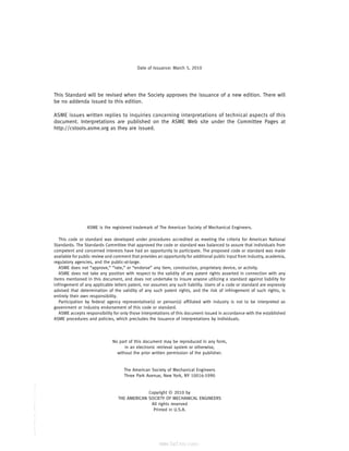
The bolted flange joint assembly (BFJA) guidelines
described in this document apply to pressure-boundary
flanged joints with ring-type gaskets that are entirely
within the circle enclosed by the bolt holes and with no
contact outside this circle.1
By selection of those features
suitable to the specific service or need, these guidelines
may be used to develop effective joint assembly proce-
dures for the broad range of sizes and service conditions
normally encountered in industry.
Guidance on troubleshooting BFJAs not providing
leak-tight performance is also provided in this document
(Appendix P).
2 INTRODUCTION
A BFJA is a complex mechanical device; therefore,
BFJAs that provide leak-free service are the result of
many selections/activities having been made/per-
formed within a relatively narrow band of acceptable
limits. One of the activities essential to leak-free per-
formance is the joint assembly process. The guidelines
outlined in this document cover the assembly elements
essential for a high level of leak-tightness integrity of
otherwise properly designed/constructed BFJAs. It is
recommended that written procedures, incorporating
the features of these guidelines that are deemed suitable
to the specific application under consideration, be devel-
oped for use by the joint assemblers. Alternative features
and methods for specific applications may be used sub-
ject to endorsement by the user or his designated agent.
3 TRAINING, QUALIFICATION, AND CERTIFICATION
OF JOINT ASSEMBLY PERSONNEL
It is recommended that the user or his designated
agent provide, or arrange to have provided, as appro-
priate, essential training and qualification testing of the
joint assembly personnel who will be expected to follow
procedures developed from this Guideline. Notes
1
Rules for design of bolted flanges with ring-type gaskets are
covered in Mandatory Appendix 2 of ASME Boiler and Pressure
Vessel Code, Section VIII, Division 1; see also Nonmandatory
Appendix S for supplementary considerations for bolted flanges
that are helpful to the designer of Appendix 2 flanges.
1
regarding qualifying flanged joint assemblers are pro-
vided in Appendix A.
See section F-2 of Appendix F for comments on
accepting flange joint assembly procedures not currently
listed in these guidelines.
4 CLEANING AND EXAMINATION OF FLANGE AND
FASTENER CONTACT SURFACES
Before assembly is started, clean and examine flange
and fastener contact surfaces as described in this section.
With one exception, remove all indications of the pre-
vious gasket installation from the gasket contact sur-
faces; use approved solvents and/or soft-wire brushes,
if required, for cleaning to prevent surface contamina-
tion and damage to existing surface finish. Avoid using
carbon steel brushes on stainless steel flanges.
The exception based on experience is flexible graphite
that may remain in the surface finish grooves when
either a flexible graphite clad or a spiral-wound gasket
with flexible graphite filler is to be used as the replace-
ment gasket.
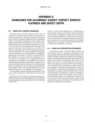
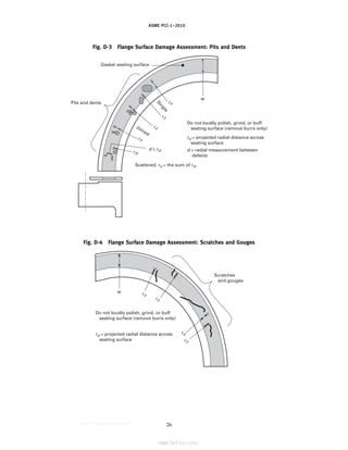
(a) Examine the gasket contact surfaces of both mat-
ing joint flanges for compliance with recommended sur-
face finish (see Appendix C) and for damage to surface
finish such as scratches, nicks, gouges, and burrs. Indica-
tions running radially across the facing are of particular
concern. Refer to Appendix D for guidelines covering
recommended limits on gasket contact surface imperfec-
tions and their locations.
(1) It is recommended that surface-finish compara-
tor gages be available to joint assembly personnel.
(2) Report any questionable imperfections for
appropriate disposition. If weld repair of imperfections
is deemed to be required, see ASME PCC-2, Article 3.5
for repair considerations. Appendix C provides recom-
mended final surface finishes.
(b) When working with problematic or critical service
[see Note (1) of Table 3] flanges of large diameter with
leak histories or suspect fabrication, it is recommended
to check gasket contact surfaces of both joint flanges for
flatness, both radially and circumferentially. This may be
accomplished in many cases using a machinist’s straight
edge and feeler gages, but using a securely mounted
run-out gage or field machining equipment capable of
--``,``,``,```,`,``,,,`,,,````,,-`-`,,`,,`,`,,`---](https://image.slidesharecdn.com/guidelinesforpressureboundarybolted-220921120801-038ce69b/85/Guidelines-for-Pressure-Boundary-Bolted-Flange-Joint-Assembly-9-320.jpg)
![ASME PCC-1–2010
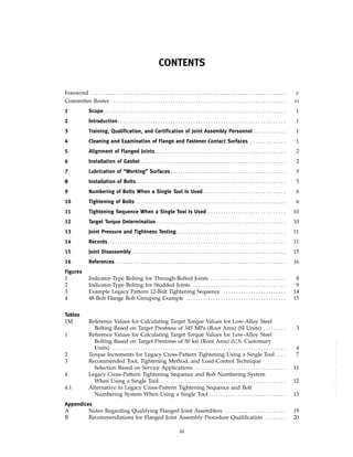
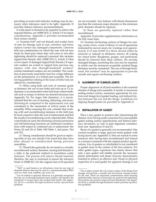
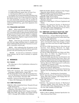
Table 1M Reference Values for Calculating Target Torque Values for Low-Alloy
Steel Bolting Based on Target Prestress of 345 MPa (Root Area) (SI Units)
(See section 12 for instructions on how to use this table.)
Target Torque, N·m
Basic Thread Designation Noncoated Bolts [Note (1)] Coated Bolts [Notes (1), (2), and (3)]
M14-2 110 85
M16-2 160 130
M20-2.5 350 250
M24-3 550 450
M27-3 800 650
M30-3 1 150 900
M33-3 1 550 1 200
M36-3 2 050 1 600
M39-3 2 650 2 050
M42-3 3 350 2 550
M45-3 4 200 3 200
M48-3 5 100 3 900
M52-3 6 600 5 000
M56-3 8 200 6 300
M64-3 12 400 9 400
M70-3 16 100 12 200
M76-3 20 900 15 800
M82-3 26 400 20 000
M90-3 35 100 26 500
M95-3 41 600 31 500
M100-3 48 500 36 700
GENERAL NOTE: The values shown are based on a Target Prestress of 345 MPa (root area). See section 12
(Target Torque Determination). The root areas are based on coarse-thread series for sizes M27 and smaller,
and 3 mm pitch thread series for sizes M30 and larger.
NOTES:
(1) Computed values are based on “working” surfaces that comply with section 4 (Cleaning and
Examination of Flange and Fastener Contact Surfaces) and section 7 (Lubrication of “Working”
Surfaces), and the following coefficients of friction: 0.16 for noncoated surfaces and 0.12 for new
coated surfaces. These coefficients were selected to make the computed Target Torques consistent
with that needed for a Target Prestress of 345 MPa as independently verified by accurate bolt
elongation measurements by several users. (See Appendix K for equivalent nut factors.)
(2) The coating on coated bolts is polyimide/amide and is considered to be the sole source of
“working” surface lubrication; the application of a lubricant to the coated surfaces can result in a
considerable reduction in the assumed coefficient of friction of 0.12. (See Appendix K for
equivalent nut factor.)
(3) Coated torque values apply only for initial tightening of new, coated bolts using the torque-
increment rounds shown in Table 2. For second and subsequent tightening by torquing methods,
use of lubricants and torque values as specified for noncoated bolts is recommended.
3
--``,``,``,```,`,``,,,`,,,````,,-`-`,,`,,`,`,,`---](https://image.slidesharecdn.com/guidelinesforpressureboundarybolted-220921120801-038ce69b/85/Guidelines-for-Pressure-Boundary-Bolted-Flange-Joint-Assembly-11-320.jpg)
![ASME PCC-1–2010
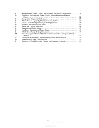
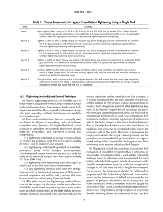
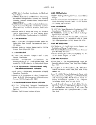
Table 1 Reference Values for Calculating Target Torque Values for Low-Alloy
Steel Bolting Based on Target Prestress of 50 ksi (Root Area)
(U.S. Customary Units)
(See section 12 for instructions on how to use this table.)
Target Torque, ft-lb
Nominal Bolt Size, in. Noncoated Bolts [Note (1)] Coated Bolts [Notes (1), (2), and (3)]
1
⁄2 60 45
5
⁄8 120 90
3
⁄4 210 160
7
⁄8 350 250
1 500 400
11
⁄8 750 550
11
⁄4 1,050 800
13
⁄8 1,400 1,050
11
⁄2 1,800 1,400
15
⁄8 2,350 1,800
13
⁄4 2,950 2,300
17
⁄8 3,650 2,800
2 4,500 3,400
21
⁄4 6,500 4,900
21
⁄2 9,000 6,800
23
⁄4 12,000 9,100
3 15,700 11,900
31
⁄4 20,100 15,300
31
⁄2 25,300 19,100
33
⁄4 31,200 23,600
4 38,000 28,800
GENERAL NOTE: The values shown are based on a Target Prestress of 50 ksi (root area). See section 12
(Target Torque Determination). The root areas are based on coarse-thread series for sizes 1 in. and smaller,
and 8-pitch thread series for sizes 11
⁄8 in. and larger.
NOTES:
(1) Computed values are based on “working” surfaces that comply with section 4 (Cleaning and
Examination of Flange and Fastener Contact Surfaces) and section 7 (Lubrication of “Working”
Surfaces), and the following coefficients of friction: 0.16 for noncoated surfaces and 0.12 for new
coated surfaces. These coefficients were selected to make the computed Target Torques consistent
with that needed for a Target Prestress of 50 ksi as independently verified by accurate bolt
elongation measurements by several users. (See Appendix K for equivalent nut factors.)
(2) The coating on coated bolts is polyimide/amide and is considered to be the sole source of
“working” surface lubrication; the application of a lubricant to the coated surfaces can result in a
considerable reduction in the assumed coefficient of friction of 0.12. (See Appendix K for
equivalent nut factor.)
(3) Coated torque values apply only for initial tightening of new, coated bolts using the torque-
increment rounds shown in Table 2. For second and subsequent tightening by torquing methods,
use of lubricants and torque values as specified for noncoated bolts is recommended.
4
--``,``,``,```,`,``,,,`,,,````,,-`-`,,`,,`,`,,`---
标准分享网 www.bzfxw.com 免费下载](https://image.slidesharecdn.com/guidelinesforpressureboundarybolted-220921120801-038ce69b/85/Guidelines-for-Pressure-Boundary-Bolted-Flange-Joint-Assembly-12-320.jpg)
![ASME PCC-1–2010
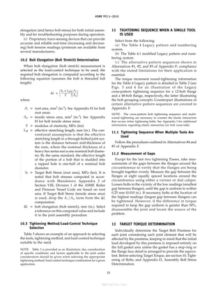
sufficient to detect such sealing surface factors as work-
hardening, brittleness, or the affects of heat or interaction
with the service fluid.
(a) Verify that the gasket complies with the dimen-
sional (O.D., I.D., thickness) and material specifications.
(b) Position the gasket to be concentric with the flange
I.D., taking suitable measures to ensure that it is ade-
quately supported during the positioning process. No
portion of the gasket should project into the flow path.
(c) Ensure that the gasket will remain in place during
the joint assembly process; a very light dusting of spray
adhesive on the gasket (not the flange) may be used.
Particular care should be taken to avoid adhesive chem-
istry that is incompatible with the process fluid or could
result in stress corrosion cracking or pitting of the flange
surfaces. Do not use tape strips radially across the gasket to
hold it in position. Do not use grease.
7 LUBRICATION OF “WORKING” SURFACES5
Lubrication reduces the coefficient of friction and
results in less required torque to achieve a given tension,
improves the consistency of achieved load from bolt to
bolt within the joint, and aids in the subsequent disas-
sembly of the fasteners.
The reference torque values for new, coated bolts/
nuts shown in Table 1M/Table 1 do not consider lubrica-
tion other than that provided by the bolt/nut coating
[see Note (2) of Table 1M/Table 1]. When reusing coated
bolts or if lubricant is applied to new or reused coated
bolts, the Nut Factor will change and therefore the torque
values should be adjusted accordingly (refer to
Appendix K). Do not apply either approved lubricant or
unapproved compounds to the gasket or gasket-contact
surfaces; protect against inadvertent application to these
surfaces.
(a) Ensure that the lubricant is chemically compatible
with the bolt/nut/washer materials and the process
fluid. Particular care should be taken to avoid lubricant
chemistry that could contribute to stress corrosion crack-
ing, galvanic corrosion, oxygen auto-ignition, etc.
(b) Ensure that the lubricant has proven to be suitable
for the expected range of service temperature(s) and
antiseize requirements.
(c) Before lubricant is applied to the bolt and nut
threads, nuts must run freely by hand past where they
will come to rest after tightening. If nuts will not turn
freely by hand, check for cause and make necessary
corrections/replacements.
(d) For noncoated bolts (see Notes to Table 1M/
Table 1), apply lubricant liberally and completely to the
nut contact faces and to the threads on both ends of
the bolts past where the nuts will come to rest after
5
The term “working” surfaces refers to those interfaces between
fastener components and/or fasteners and flanges that slide past
one another during tightening or loosening.
5
tightening; the lubricant should be applied after the
bolts are inserted through the flange bolt holes to avoid
possible contamination with solid particles that could
create unwanted reaction torque.
(e) For new coated bolts and nuts (see Notes to
Table 1M/Table 1), free running nut checks as described
in (c) are required; however, lubricant application as
described in (d) should be limited to the second and
subsequent tightening operations since the coating pro-
vides sufficient lubrication for the first tightening.
(1) The reference torque values for new, coated
bolts/nuts shown in Table 1M/Table 1 do not consider
lubrication other than that provided by the bolt/nut
coating [see Note (2) of Table 1M/Table 1]. When reusing
coated bolts or if lubricant is applied to new or reused
coated bolts, the Nut Factor will change and therefore
the torque values should be adjusted accordingly (refer
to Appendix K).
(f) While it is recognized that the inherent lubricity
of new coated bolts results in less torque being required
during the first tightening operation to achieve a given
level of tension in the bolt (see Table 1M/Table 1), the
major long-term value of coated bolts is to protect
against corrosion of the exposed threads and to mini-
mize break-out and nut-removal torque, thereby pro-
moting ease of joint disassembly [see section 15, and
Note (3) of Table 1M/Table 1].
(g) Do not apply either approved lubricant or unap-
proved compounds to the gasket or gasket-contact sur-
faces; protect against inadvertent application to these
surfaces.
8 INSTALLATION OF BOLTS
Install bolts and nuts so they are hand-tight with the
marked ends of the bolts and nuts located on the same
side of the joint and facing outward to facilitate inspec-
tion; then snug up to 15 N·m (10 ft-lb) to 30 N·m (20 ft-lb),
but not to exceed 20% of the Target Torque (see section
12). If nuts do not hand tighten, check for cause and
make necessary corrections.
8.1 Bolt/Nut Specifications
Verify compliance with bolt and nut specifications
[materials, diameter, length of bolts, thread pitch, and
nut thickness equal to the nominal bolt diameter (heavy
hex series nuts)].
8.2 Bolt Lengths
Check bolts for adequate length. Section VIII, Division
1 of the ASME Boiler and Pressure Vessel Code requires
that nuts engage the threads for the full depth of the
nut (see para. UG-13). The ASME B31.3, Process Piping
Code, has a similar provision but considers the nut to
be acceptably engaged if the lack of complete engage-
ment is not more than one thread (see para. 335.2.3). See
--``,``,``,```,`,``,,,`,,,````,,-`-`,,`,,`,`,,`---](https://image.slidesharecdn.com/guidelinesforpressureboundarybolted-220921120801-038ce69b/85/Guidelines-for-Pressure-Boundary-Bolted-Flange-Joint-Assembly-13-320.jpg)
![ASME PCC-1–2010
para. 10.1(c) of this document if use of hydraulic bolt
tensioners is planned.
8.2.1 Corrosion of excess threads can hinder joint
disassembly. A practice that facilitates joint disassembly
(see section 15) is to fully engage the nut on one end
(no bolt projection beyond the nut) so that all excess
threads are located on the opposite end; the excess
threads should not project more than 13 mm (1
⁄2 in.)
beyond the nut, unless required for the use of hydraulic
bolt tensioners [see para. 10.1(c)].
8.2.2 When the effective stretching length (“Leff,”
see para. 10.2) is short,6
the total initial bolt elongation
(⌬L; see para. 10.2) resulting from the determined Target
Bolt Stress (see section 12) will be a proportionately
small value, thereby resulting in a significant percentage
reduction in the post-assembly bolt stress due to normal
gasket creep, embedment losses, and joint heat-up. The
sensitivity to this occurrence should be given careful
attention along with other joint considerations when
selecting the level of Target Bolt Stress.
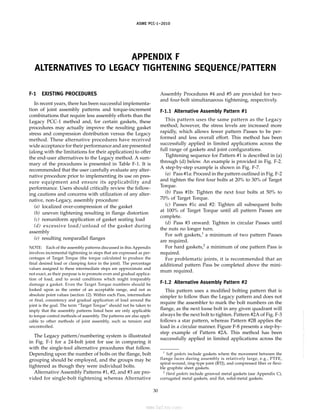
9 NUMBERING OF BOLTS WHEN A SINGLE TOOL
IS USED
Two optional bolt numbering systems that are pre-
sented in this Guideline are as follows:
(a) A system whereby each bolt location, starting with
No. 1 and continuing through N, is numbered sequen-
tially on the flange in a clockwise manner (where N is
the total number of bolts in the joint). This system was
used in ASME PCC-1–2000. It has been retained (there-
fore referenced as the Legacy system), and is the basis
for the Table 4, Legacy Cross-Pattern Tightening
Sequence and Bolt Numbering System. This numbering
system allows, for example, the quick identification of
bolt number 20 in a 40-bolt flange, but requires a refer-
ence table such as Table 4 for the tightening sequence
during the tightening process.
(b) The alternative numbering system (see Table 4.1)
is designed so that the number assigned at each bolt
location represents the sequential order for tightening
that bolt; in other words the cross-pattern tightening
sequence is identified by the assigned bolt number and,
therefore, a separate reference table is not required dur-
ing the tightening process.
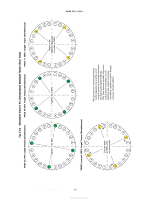
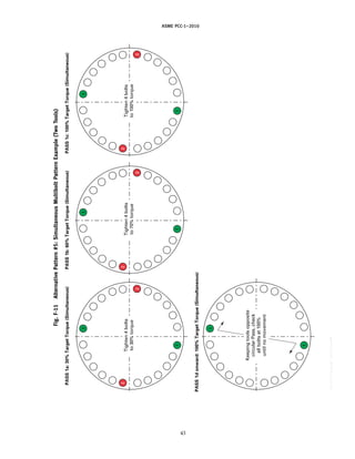
See Appendix F for joint assembly patterns and
torque-increment combinations that require less assem-
bly effort than the Table 4 Legacy and the Table 4.1
modified Legacy methods.
9.1 Numbering of Bolts When Multiple Tools Are
Used
See Appendix F (Alternative Patterns #4 and #5).
6
A bolt having an effective length shorter than 5 times its nominal
diameter is generally considered to be “short.”
6
10 TIGHTENING OF BOLTS
Using the selected tightening method/load-control
technique (see para. 10.1), tighten the joint using either
the torque increment rounds shown in Table 2 and either
the companion Table 4 or Table 4.1 cross-pattern tight-
ening sequences when using a single tool as described
in section 11, or one of the alternative tightening/
numbering systems shown in Alternatives #1, #2, and
#3 of Appendix F.
Alternatives #4 and #5 illustrate alternative group
numbering systems and tightening sequences when
simultaneously using multiple tools.
NOTE: When hydraulic bolt tensioners are employed, use the
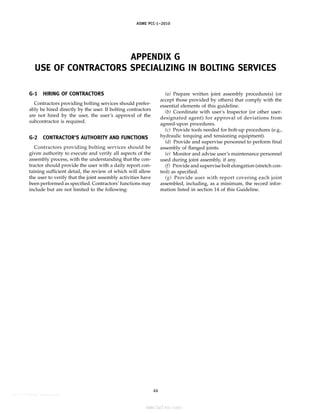
procedure recommended by personnel who are experienced and
qualified in controlled bolting services. Guidelines on use of con-
tractors specializing in bolting services are provided in
Appendix G.
It is recognized by Appendix S of the ASME Boiler
and Pressure Vessel Code, Section VIII, Division 1 that
the initial tightening of the bolts in a joint comprising
flanges designed in accordance with Appendix 2 of that
Code is a prestressing operation and that the level of
required Target Bolt Prestress can vary considerably
above the code tabulated design-stress value. This is an
acceptable and usually required practice. Appendix S
states that “. . . an initial bolt stress higher than the
design value may and, in some cases, must be developed
in the tightening operation, and it is the intent of this
Division that such a practice is permissible, provided it
includes necessary and appropriate provision to ensure
against excessive flange distortion and gross crushing
of the gasket.” For joints custom designed in accordance
with Appendix 2, a common range of Target Bolt
Prestress that is often found acceptable is around 40%
to 70% of the specified minimum yield strength of the
bolt material (see also para. 8.2.2 regarding the effect of
short bolts on the determination of the Target Torque
value). This range is normally only exceeded in excep-
tional cases that have been assessed by a qualified engi-
neer. However, any maximum Target Bolt Prestress must
be selected to ensure that all three of the joint compo-
nents — bolts, flange, and gasket — are stressed within
acceptable limits.
Section 12 provides guidance on the determination of
the assembly Target Torque value.
Appendix O outlines a method to determine the
assembly bolt stress for a given flange joint (bolt, flange,
gasket assembly). The method is based on a formula and
flange stress limits that are supported by and consistent
with elastic–plastic FEA work. A calculation is provided
that uses an example-specific maximum allowable gas-
ket stress; however, the user must provide this informa-
tion. Tables for maximum bolt load limits are provided
for ASME B16.5/B16.47 Series A flanges and the method
to calculate the assembly bolt load for other standard
and nonstandard flanges is outlined.
--``,``,``,```,`,``,,,`,,,````,,-`-`,,`,,`,`,,`---
标准分享网 www.bzfxw.com 免费下载](https://image.slidesharecdn.com/guidelinesforpressureboundarybolted-220921120801-038ce69b/85/Guidelines-for-Pressure-Boundary-Bolted-Flange-Joint-Assembly-14-320.jpg)
![www.bzfxw.com
ASME PCC-1–2010
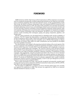
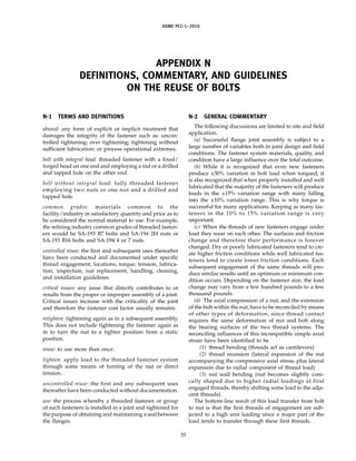
Fig.
1
Indicator-Type
Bolting
for
Through-Bolted
Joints
Indicator
rod
material
for
low-alloy
steel
bolting
(e.g.,
SA-193
GR-B7)
shall
be
nickel
alloy
UNS
N10276
(C-276)
bare
welding
rod
per
AWS
A5.14.
Indicator
rod
material
for
other
bolting
shall
be
same
as
bolt,
or
a
material
having
essentially
the
same
coefficient
of
expansion
and
a
composition
suitable
for
welding
to
the
bolt.
Indicator
rod
diameter
to
be
reduced
by
centerless
grinding
if
necessary
to
provide
free-fall
movement
of
rod
before
welding.
Washers
are
required
only
when
torquing
methods
(versus
use
of
hydraulic
tensioners)
are
used
for
bolt
tightening.
NOTES:
(1)
(2)
(3)
Drawn
by
Checked
by
Approved
by
Indicator-Type
Bolting
for
Through-Bolted
Joints
Date
Drawing
Number
For
Item
Number
,
see
Reference
Drawing
.
Machine
grind
end
of
bolt
and
indicator
rod
flush
after
rod
is
welded
in
place.
This
end
only.
A
–A–
.001
Drill
through
from
one
end
only
with
hole
centerline
coincident
with
axis
of
bolt
(see
Table
A)
32
Indicator
rod
[see
Table
A
and
Notes
(1)
and
(2)]
Thread
bolt
full
length
(see
Table
B)
Bolt
marking
off
center
on
welded
end
of
bolt
(do
not
deface
marking)
Washers;
two
required
per
bolt
[see
Note
(3)
and
Appendix
M]
Heavy
hex
nut;
two
required
per
bolt
(see
Table
B)
Weld
this
end
of
indicator
rod
to
bolt.
Do
not
grind
after
welding.
L
(see
Table
B)
Nominal
Bolt
Diameter,
in.
Quantity
Required
Materials
Bolt
Nuts
L
Nominal
Bolt
Diameter,
in.
7
/
8
–1
1
/
4
1
3
/
8
–1
7
/
8
Over
2
0.313
0.002
0.000
0.250
0.002
0.000
0.188
0.002
0.000
1
/
8
3
/
16
1
/
4
TABLE
A
TABLE
B
Indicator
Rod
Diameter,
in.
[Note
(2)]
Hole
Diameter,
in.
8
--``,``,``,```,`,``,,,`,,,````,,-`-`,,`,,`,`,,`---
标准分享网 www.bzfxw.com 免费下载](https://image.slidesharecdn.com/guidelinesforpressureboundarybolted-220921120801-038ce69b/85/Guidelines-for-Pressure-Boundary-Bolted-Flange-Joint-Assembly-16-320.jpg)
![www.bzfxw.com
ASME PCC-1–2010
Fig.
2
Indicator-Type
Bolting
for
Studded
Joints
Indicator-Type
Bolting
for
Studded
Joints
Washer
[see
Note
(3)
and
Appendix
M]
Externally
relieved
end
Plug
weld
this
end
of
indicator
rod
to
bolt.
Minimize
weld
projection
beyond
end
of
bolt.
Heavy
hex
nut
(see
Table
B)
Indicator
rod
material
for
low-alloy
steel
bolting
(e.g.,
SA-193
GR-B7)
shall
be
nickel
alloy
UNS
N10276
(C-276)
bare
welding
rod
per
AWS
A5.14.
Indicator
rod
material
for
other
bolting
shall
be
same
as
bolt,
or
a
material
having
essentially
the
same
coefficient
of
expansion
and
a
composition
suitable
for
welding
to
the
bolt.
Indicator
rod
diameter
to
be
reduced
by
centerless
grinding
if
necessary
to
provide
free-fall
movement
of
rod
before
welding.
Washers
are
required
only
when
torquing
methods
(versus
use
of
hydraulic
tensioners)
are
used
for
bolt
tightening.
NOTES:
(1)
(2)
(3)
Drawn
by
Checked
by
Approved
by
Date
Drawing
Number
For
Item
Number
,
see
Reference
Drawing
.
Machine
grind
end
of
bolt
and
indicator
rod
flush
after
rod
is
welded
in
place.
This
end
only.
A
–A–
.001
Drill
through
from
one
end
only
with
hole
centerline
coincident
with
axis
of
bolt
(see
Table
A)
32
Indicator
rod
[see
Table
A
and
Notes
(1)
and
(2)]
Thread
bolt
full
length
(see
Table
B)
Bolt
marking
off
center
on
welded
end
of
bolt
(do
not
deface
marking)
L
(see
Table
B)
Nominal
Bolt
Diameter,
in.
Quantity
Required
Materials
Bolt
Nuts
L
Nominal
Bolt
Diameter,
in.
7
/
8
–1
1
/
4
1
3
/
8
–1
7
/
8
Over
2
0.313
0.002
0.000
0.250
0.002
0.000
0.188
0.002
0.000
1
/
8
3
/
16
1
/
4
TABLE
A
TABLE
B
Indicator
Rod
Diameter,
in.
[Note
(2)]
Hole
Diameter,
in.
9
--``,``,``,```,`,``,,,`,,,````,,-`-`,,`,,`,`,,`---](https://image.slidesharecdn.com/guidelinesforpressureboundarybolted-220921120801-038ce69b/85/Guidelines-for-Pressure-Boundary-Bolted-Flange-Joint-Assembly-17-320.jpg)
![www.bzfxw.com
ASME PCC-1–2010
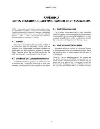
Table 3 Recommended Tool, Tightening Method, and Load-Control Technique Selection
Based on Service Applications
(See para. 10.1)
Service Applications
[Note (1)] Tools [Note (2)] Tightening Method Load-Control Technique
Mild Service Manual or auxiliary powered tools Pattern single or multibolt Consistent procedures per
tightening procedures industry best practices or
torque control
Intermediate Service Manual or auxiliary powered tools Pattern single or multibolt [Note (3)]
or torque or tension measuring tightening procedures
tools
Critical Service Torque or tension measuring Pattern single or multibolt Torque or tension control with
tools tightening procedures final bolt elongation/load
verification optional [Note (4)]
NOTES:
(1) Service Applications should be designated by the user and should consider governing design conditions (pressure, temperature, etc.),
mechanical criteria (bolt diameter, flange diameter, gasket type, etc.), joint leakage history, and fluid service category.
(a) An example of Mild Service could include Category D Fluid Service as defined in ASME B31.3.
(b) An example of Intermediate Service could include Normal Fluid Service as defined in ASME B31.3.
(c) Examples of Critical Service could include service requirements as defined by local jurisdictional requirements [example for
United States is CFR 1910.119 (OSHA PSM rule)], lethal substance service as defined in the ASME Section VIII, Division 1 Code, or
Category M Fluid Service as defined in ASME B31.3.
(2) All tools are to be regularly and properly maintained and calibrated.
(3) It is recognized that many joints are regularly tightened using impact wrenches or manual tools with no precise load control. Experi-
ence may prove this is sufficient for certain applications but unmeasured tightening is not recommended for intermediate service appli-
cations without careful consideration of the risks.
(4) Where past practice with specific or similar equipment warrant or where testing/research validates; elongation and load verification
may be waived.
12.1 Target Prestress
The Reference Torques for a Target Prestress of
345 MPa (50 ksi) (root area) are given in Table 1M/
Table 1. Target Torques for different Target Prestress
levels may be obtained by reducing (or increasing) the
values in Table 1M/Table 1 by the ratio
Target Prestress (MPa)
345 (MPa)
or
Target Prestress (ksi)
50 (ksi)
See Appendix J for calculation of Target Torque for
coefficients of friction other than those listed in Note (1)
of Table 1M/Table 1. See Appendix K for an alternative
method of calculating Target Torque when nut factors
are used.
13 JOINT PRESSURE AND TIGHTNESS TESTING
Bolted joint assemblies should be tested to ensure leak
tightness. Subject to code/regulatory requirements, the
user should establish
(a) the type of leak test (e.g., visual, bubble-forming
solution, sniffer)
(b) test fluid (e.g., air, inert gas, water, service fluid)
11
(c) test pressure (e.g., low pressure or up to a code-
mandated visual inspection pressure)
(d) acceptance criteria (often simply “no detectable
leaks”).
The user is also cautioned to consider that the practice
of using “temporary” gaskets for pressure or tightness
testing of systems that include bolted flange joint assem-
blies has resulted in numerous incidents of injury and
near injury to assembly personnel due to “blow out”
failure of these alternative gasket materials/types. The
use of substitute gaskets during testing instead of those
designed as the final seal for the joint is not recom-
mended.
Refer to ASME PCC-2, Article 5.1 for general good
practices for pressure and tightness testing of pressure
equipment.
14 RECORDS
Consideration should be given to the preparation of
a joint assembly record for each assembled joint, particu-
larly those that are deemed to be in critical service. This
record, which could be a logbook entry, would serve as
a helpful resource for troubleshooting purposes, future
assemblies, etc. The record could include but not neces-
sarily be limited to the following information:
(a) date of assembly
--``,``,``,```,`,``,,,`,,,````,,-`-`,,`,,`,`,,`---](https://image.slidesharecdn.com/guidelinesforpressureboundarybolted-220921120801-038ce69b/85/Guidelines-for-Pressure-Boundary-Bolted-Flange-Joint-Assembly-19-320.jpg)
![www.bzfxw.com
ASME PCC-1–2010
Table 4 Legacy Cross-Pattern Tightening Sequence and Bolt Numbering System
When Using a Single Tool
No. of
Bolts Sequentially Clockwise Sequence [Note (1)]
4 1-3-2-4
8 1-5-3-7 → 2-6-4-8
12 1-7-4-10 → 2-8-5-11 → 3-9-6-12
16 1-9-5-13 → 3-11-7-15 → 2-10-6-14 → 4-12-8-16
20 1-11-6-16 → 3-13-8-18 → 5-15-10-20 → 2-12-7-17 → 4-14-9-19
24 1-13-7-19 → 4-16-10-22 → 2-14-8-20 → 5-17-11-23 → 3-15-9-21 → 6-18-12-24
28 1-15-8-22 → 4-18-11-25 → 6-20-13-27 → 2-16-9-23 → 5-19-12-26 → 7-21-14-28 ↵
3-17-10-24
32 1-17-9-25 → 5-21-13-29 → 3-19-11-27 → 7-23-15-31 → 2-18-10-26 → 6-22-14-30 ↵
4-20-12-28 → 8-24-16-32
36 1-2-3 → 19-20-21 → 10-11-12 → 28-29-30 → 4-5-6 → 22-23-24 → 13-14-15 ↵
31-32-33 → 7-8-9 → 25-26-27 → 16-17-18 → 34-35-36
40 1-2-3-4 → 21-22-23-24 → 13-14-15-16 → 33-34-35-36 → 5-6-7-8 → 25-26-27-28 ↵
17-18-19-20 → 37-38-39-40 → 9-10-11-12 → 29-30-31-32
44 1-2-3-4 → 25-26-27-28 → 13-14-15-16 → 37-38-39-40 → 5-6-7-8 → 29-30-31-32 ↵
17-18-19-20 → 41-42-43-44 → 9-10-11-12 → 33-34-35-36 → 21-22-23-24
48 1-2-3-4 → 25-26-27-28 → 13-14-15-16 → 37-38-39-40 → 5-6-7-8 → 29-30-31-32 ↵
17-18-19-20 → 41-42-43-44 → 9-10-11-12 → 33-34-35-36 → 21-22-23-24 → 45-46-47-48
52 1-2-3-4 → 29-30-31-32 → 13-14-15-16 → 41-42-43-44 → 5-6-7-8 → 33-34-35-36 ↵
17-18-19-20 → 45-46-47-48 → 21-22-23-24 → 49-50-51-52 → 25-26-27-28 ↵
9-10-11-12 → 37-38-39-40
56 1-2-3-4 → 29-30-31-32 → 13-14-15-16 → 41-42-43-44 → 21-22-23-24 → 49-50-51-52 ↵
9-10-11-12 → 37-38-39-40 → 25-26-27-28 → 53-54-55-56 → 17-18-19-20 ↵
45-46-47-48 → 5-6-7-8 → 33-34-35-36
60 1-2-3-4 → 29-30-31-32 → 45-46-47-48 → 13-14-15-16 → 5-6-7-8 → 37-38-39-40 ↵
21-22-23-24 → 53-54-55-56 → 9-10-11-12 → 33-34-35-36 → 49-50-51-52 → 17-18-19-20 ↵
41-42-43-44 → 57-58-59-60 → 25-26-27-28
64 1-2-3-4 → 33-34-35-36 → 17-18-19-20 → 49-50-51-52 → 9-10-11-12 → 41-42-43-44 ↵
25-26-27-28 → 57-58-59-60 → 5-6-7-8 → 37-38-39-40 → 21-22-23-24 → 53-54-55-56 ↵
13-14-15-16 → 45-46-47-48 → 29-30-31-32 → 61-62-63-64
68 1-2-3-4 → 37-38-39-40 → 21-22-23-24 → 53-54-55-56 → 9-10-11-12 → 45-46-47-48 ↵
29-30-31-32 → 61-62-63-64 → 17-18-19-20 → 57-58-59-60 → 33-34-35-36 → 5-6-7-8 ↵
41-42-43-44 → 13-14-15-16 → 49-50-51-52 → 25-26-27-28 → 65-66-67-68
GENERAL NOTES:
(a) See Table 4.1 covering a modified Legacy pattern and numbering system.
(b) See Appendix F for Alternatives #1, #2, and #3 to Legacy Table 2, torque increments, and Legacy Table 4, single-tool tightening and
bolt numbering. Compliance with the limitations of the application of these alternatives is essential.
(c) See Appendix F for Alternatives #4 and #5 for alternative group numbering and tightening sequence when simultaneously using
multiple tools.
NOTE:
(1) See Figs. 3 and 4 for illustrations of Legacy cross-pattern tightening sequences and bolt numbering system when using a single tool.
12
--``,``,``,```,`,``,,,`,,,````,,-`-`,,`,,`,`,,`---
标准分享网 www.bzfxw.com 免费下载](https://image.slidesharecdn.com/guidelinesforpressureboundarybolted-220921120801-038ce69b/85/Guidelines-for-Pressure-Boundary-Bolted-Flange-Joint-Assembly-20-320.jpg)
![www.bzfxw.com
ASME PCC-1–2010
Table 4.1 Alternative to Legacy Cross-Pattern Tightening Sequence and Bolt Numbering System
When Using a Single Tool
(See section 9)
No. of
Bolts Bolt Numbering Sequence to Be Marked Clockwise on Flange [Note (1)]
4 1, 3, 2, 4
8 1, 5, 3, 7, 2, 6, 4, 8
12 1, 9, 5, 3, 11, 7, 2, 10, 6, 4, 12, 8
16 1, 9, 5, 13, 3, 11, 7, 15, 2, 10, 6, 14, 4, 12, 8, 16
20 1, 17, 9, 5, 13, 3, 19, 11, 7, 15, 2, 18, 10, 6, 14, 4, 20, 12, 8, 16
24 1, 17, 9, 5, 13, 21, 3, 19, 11, 7, 15, 23, 2, 18, 10, 6, 14, 22, 4, 20, 12, 8, 16, 24
28 1, 25, 17, 9, 5, 13, 21, 3, 27, 19, 11, 7, 15, 23, 2, 26, 18, 10, 6, 14, 22, 4, 28, 20, 12, 8, 16, 24
32 1, 25, 17, 9, 5, 13, 21, 29, 3, 27, 19, 11, 7, 15, 23, 31, 2, 26, 18, 10, 6, 14, 22, 30, 4, 28, 20, 12, 8, 16, 24, 32
36 1, 33, 25, 17, 9, 5, 13, 21, 29, 3, 35, 27, 19, 11, 7, 15, 23, 31, 2, 34, 26, 18, 10, 6, 14, 22, 30, 4, 36, 28, 20, 12, 8,
16, 24, 32
40 1, 33, 25, 17, 9, 5, 13, 21, 29, 37, 3, 35, 27, 19, 11, 7, 15, 23, 31, 39, 2, 34, 26, 18, 10, 6, 14, 22, 30, 38, 4, 36, 28,
20, 12, 8, 16, 24, 32, 40
44 1, 41, 33, 25, 17, 9, 5, 13, 21, 29, 37, 3, 43, 35, 27, 19, 11, 7, 15, 23, 31, 39, 2, 42, 34, 26, 18, 10, 6, 14, 22, 30, 38,
4, 44, 36, 28, 20, 12, 8, 16, 24, 32, 40
48 1, 41, 33, 25, 17, 9, 5, 13, 21, 29, 37, 45, 3, 43, 35, 27, 19, 11, 7, 15, 23, 31, 39, 47, 2, 42, 34, 26, 18, 10, 6, 14, 22,
30, 38, 46, 4, 44, 36, 28, 20, 12, 8, 16, 24, 32, 40, 48
52 1, 49, 41, 33, 25, 17, 9, 5, 13, 21, 29, 37, 45, 3, 51, 43, 35, 27, 19, 11, 7, 15, 23, 31, 39, 47, 2, 50, 42, 34, 26, 18, 10,
6, 14, 22, 30, 38, 46, 4, 52, 44, 36, 28, 20, 12, 8, 16, 24, 32, 40, 48
56 1, 49, 41, 33, 25, 17, 9, 5, 13, 21, 29, 37, 45, 53, 3, 51, 43, 35, 27, 19, 11, 7, 15, 23, 31, 39, 47, 55, 2, 50, 42, 34, 26,
18, 10, 6, 14, 22, 30, 38, 46, 54, 4, 52, 44, 36, 28, 20, 12, 8, 16, 24, 32, 40, 48, 56
60 1, 57, 49, 41, 33, 25, 17, 9, 5, 13, 21, 29, 37, 45, 53, 3, 59, 51, 43, 35, 27, 19, 11, 7, 15, 23, 31, 39, 47, 55, 2, 58, 50,
42, 34, 26, 18, 10, 6, 14, 22, 30, 38, 46, 54, 4, 60, 52, 44, 36, 28, 20, 12, 8, 16, 24, 32, 40, 48, 56
13
--``,``,``,```,`,``,,,`,,,````,,-`-`,,`,,`,`,,`---](https://image.slidesharecdn.com/guidelinesforpressureboundarybolted-220921120801-038ce69b/85/Guidelines-for-Pressure-Boundary-Bolted-Flange-Joint-Assembly-21-320.jpg)
![www.bzfxw.com
ASME PCC-1–2010
Table 4.1 Alternative to Legacy Cross-Pattern Tightening Sequence and Bolt Numbering System
When Using a Single Tool (Cont’d)
(See section 9)
No. of
Bolts Bolt Numbering Sequence to Be Marked Clockwise on Flange [Note (1)]
64 1, 57, 49, 41, 33, 25, 17, 9, 5, 13, 21, 29, 37, 45, 53, 61, 3, 59, 51, 43, 35, 27, 19, 11, 7, 15, 23, 31, 39, 47, 55, 63, 2,
58, 50, 42, 34, 26, 18, 10, 6, 14, 22, 30, 38, 46, 54, 62, 4, 60, 52, 44, 36, 28, 20, 12, 8, 16, 24, 32, 40, 48, 56, 64
68 1, 65, 57, 49, 41, 33, 25, 17, 9, 5, 13, 21, 29, 37, 45, 53, 61, 3, 67, 59, 51, 43, 35, 27, 19, 11, 7, 15, 23, 31, 39, 47, 55,
63, 2, 66, 58, 50, 42, 34, 26, 18, 10, 6, 14, 22, 30, 38, 46, 54, 62, 4, 68, 60, 52, 44, 36, 28, 20, 12, 8, 16, 24, 32, 40,
48, 56, 64
72 1, 65, 57, 49, 41, 33, 25, 17, 9, 5, 13, 21, 29, 37, 45, 53, 61, 69, 3, 67, 59, 51, 43, 35, 27, 19, 11, 7, 15, 23, 31, 39, 47,
55, 63, 71, 2, 66, 58, 50, 42, 34, 26, 18, 10, 6, 14, 22, 30, 38, 46, 54, 62, 70, 4, 68, 60, 52, 44, 36, 28, 20, 12, 8, 16,
24, 32, 40, 48, 56, 64, 72
76 1, 73, 65, 57, 49, 41, 33, 25, 17, 9, 5, 13, 21, 29, 37, 45, 53, 61, 69, 3, 75, 67, 59, 51, 43, 35, 27, 19, 11, 7, 15, 23, 31,
39, 47, 55, 63, 71, 2, 74, 66, 58, 50, 42, 34, 26, 18, 10, 6, 14, 22, 30, 38, 46, 54, 62, 70, 4, 76, 68, 60, 52, 44, 36, 28,
20, 12, 8, 16, 24, 32, 40, 48, 56, 64, 72
80 1, 73, 65, 57, 49, 44, 33, 25, 17, 9, 5, 13, 21, 29, 37, 45, 53, 61, 69, 77, 3, 75, 67, 59, 51, 43, 35, 27, 19, 11, 7, 15, 23,
31, 39, 47, 55, 63, 71, 79, 2, 74, 66, 58, 50, 42, 34, 26, 18, 10, 6, 14, 22, 30, 38, 46, 54, 62, 70, 78, 4, 76, 68, 60, 52,
44, 36, 28, 20, 12, 8, 16, 24, 32, 40, 48, 56, 64, 72, 80
84 1, 81, 73, 65, 57, 49, 44, 33, 25, 17, 9, 5, 13, 21, 29, 37, 45, 53, 61, 69, 77, 3, 83, 75, 67, 59, 51, 43, 35, 27, 19, 11, 7,
15, 23, 31, 39, 47, 55, 63, 71, 79, 2, 82, 74, 66, 58, 50, 42, 34, 26, 18, 10, 6, 14, 22, 30, 38, 46, 54, 62, 70, 78, 4, 84,
76, 68, 60, 52, 44, 36, 28, 20, 12, 8, 16, 24, 32, 40, 48, 56, 64, 72, 80
88 1, 81, 73, 65, 57, 49, 44, 33, 25, 17, 9, 5, 13, 21, 29, 37, 45, 53, 61, 69, 77, 85, 3, 83, 75, 67, 59, 51, 43, 35, 27, 19, 11,
7, 15, 23, 31, 39, 47, 55, 63, 71, 79, 87, 2, 82, 74, 66, 58, 50, 42, 34, 26, 18, 10, 6, 14, 22, 30, 38, 46, 54, 62, 70, 78,
86, 4, 84, 76, 68, 60, 52, 44, 36, 28, 20, 12, 8, 16, 24, 32, 40, 48, 56, 64, 72, 80, 88
NOTE:
(1) The number assigned at each bolt location represents the sequential order for tightening the bolt.
Fig. 3 Example Legacy Pattern 12-Bolt Tightening Sequence
12 1
2
3
4
5
6
7
8
9
10
11
End Start
Tightening sequence for 12 bolts (Round 1 through Round 3):
1-7-4-10 2-8-5-11 3-9-6-12
14
--``,``,``,```,`,``,,,`,,,````,,-`-`,,`,,`,`,,`---
标准分享网 www.bzfxw.com 免费下载](https://image.slidesharecdn.com/guidelinesforpressureboundarybolted-220921120801-038ce69b/85/Guidelines-for-Pressure-Boundary-Bolted-Flange-Joint-Assembly-22-320.jpg)


![www.bzfxw.com
ASME PCC-1–2010
APPENDIX C
RECOMMENDED GASKET CONTACT SURFACE FINISH FOR
VARIOUS GASKET TYPES
Table C-1 Recommended Gasket Contact Surface Finish for
Various Gasket Types
Gasket Contact Surface
Finish [Note (1)]
Gasket Description m in.
Spiral-wound 3.2–6.4 125–250
Corrugated metal jacket with corrugated metal core; full width and 3.2–6.4 125–250
circumference of both sides to be covered with adhesive-backed
flexible graphite tape
Grooved metal gasket with facing layers such as flexible graphite, 3.2–6.4 125–250
PTFE, or other conformable materials
Flexible graphite reinforced with a metal interlayer insert 3.2–6.4 125–250
Grooved metal 1.6 max. 63 max.
Flat solid metal 1.6 max. 63 max.
Flat metal jacketed 2.5 max. 100 max.
Soft cut sheet, thickness ≤ 1.6 mm (1
⁄16 in.) 3.2–6.4 125–250
Soft cut sheet, thickness > 1.6 mm (1
⁄16 in.) 3.2–13 125–500
NOTE:
(1) Finishes listed are average surface roughness values and apply to either the serrated concentric or
serrated spiral finish on the gasket contact surface of the flange.
21
--``,``,``,```,`,``,,,`,,,````,,-`-`,,`,,`,`,,`---](https://image.slidesharecdn.com/guidelinesforpressureboundarybolted-220921120801-038ce69b/85/Guidelines-for-Pressure-Boundary-Bolted-Flange-Joint-Assembly-29-320.jpg)
![ASME PCC-1–2010
Fig. F-4 Alternative Assembly Pattern #3
1
2
3
4
5
6
24
23
22
21
20
19
13
14
15
16
17
18
12
11
10
9
8
7
GENERAL NOTES:
(a) Pass 1a — 20% to 30% of Target Torque: 1,13,7,19
(b) Pass 1b — 50% to 70% of Target Torque: 1,13,7,19
(c) Pass 1c — 100% of Target Torque: 1,13,7,19
(d) Pass 1d onward — 100% of Target Torque, in circular pattern,
until nuts do not turn. 1,2,3,4,5,6,7,8,9,10,11,12,13,14,15,
16,17,18,19,20,21,22,23,24 – 1,2,3, etc.
(b) Pass #1b: Tighten the same four bolts to 50% to
70% of Target Torque.
(c) Pass #1c: Tighten the same four bolts to 100% of
Target Torque.
(d) Pass #1d onward: Tighten in circular Passes at
100% of Target Torque until the nuts no longer turn.
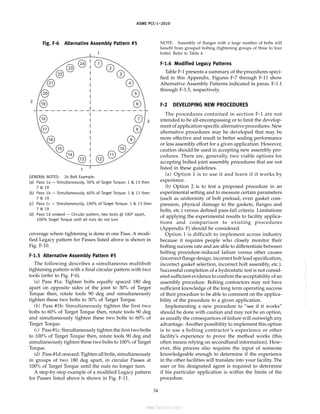
F-1.4 Alternative Assembly Pattern #4: Simultaneous
Multibolt Tightening Pattern (Group Numbering
System)
The simultaneous use of multiple tools spaced evenly
around a flange has been shown to give equal or even
superior tightening parity, and parallel closure, in less
time than using a single tool in a cross-pattern (see
Fig. F-5). This method has been successfully applied in
limited applications across the full range of gaskets and
joint configurations commonly found in refining and
petrochemical applications.
As a practical matter, multibolt tightening works best
on larger flanges [bolt diameters M20 (3
⁄4 in.) or larger],
with hydraulic tools connected to a common pressure
source. One tool per every four to eight bolts in the
flange should be used in even numbered groups of tools
equally distributed around the flange. For very critical
and/or time sensitive bolting jobs, 50% or even 100%
tool coverage is recommended.
NOTE: A minimum of four bolts are tightened simultaneously.
33
Fig. F-5 Alternative Assembly Pattern #4
1
3
5
2
4
6
6
4
2
5
3
1
1
3
5
2
4
6
6
4
2
5
3
1
24-BOLT FLANGE
4 TOOLS AT ONCE
F-1.4.1 Group Numbering. Number the flange with
the bolt sequence groups corresponding to the number
of bolts in the flange and the number of tools employed
(for this example, assume as shown in Fig. F-5, with four
tools being used to tighten).
(a) Mark the bolts at the 12, 3, 6, and 9 o’clock positions
with the number one.
(b) Moving clockwise, split the angles between the
marked bolts and number the next group as number two.
(c) Split the remaining large angles as evenly as you
can and continue numbering the groups until all bolts
are numbered. All bolts are now numbered in groups
at 90 deg from each of their own number.
F-1.4.2 Tightening. Tightening is accomplished in
three Passes.
(a) Pass #1a and #1b: Tighten approximately one-
fourth of the bolts to 50% of the Target Torque. In this
example, tighten all of the 1s and then all of the 2s to
50% of the Target Torque. It is not necessary to do the
remaining bolts because the purpose of this initial Pass
is to seat the gasket and square up the flange. Flange
alignment and gap should be checked. The remaining
bolts will have loosened so time can be saved at this
point by snugging them again.
(b) Pass #1c: Tighten all of the bolts to 100% of the
Target Torque beginning with the 3s then 4s then 5s then
6s then returning to the 1s then 2s.
(c) Pass #2 (check Pass): Beginning from the end of
the previous Pass and with the torque value still set at
100% of the target, move the tools clockwise one bolt at
a time until the nuts no longer turn. This is the check
Pass that compensates for elastic interaction and brings
all bolts into parity.
This same three-Pass procedure is used regardless of
the number of tools. The only exception would be 100%
--``,``,``,```,`,``,,,`,,,````,,-`-`,,`,,`,`,,`---](https://image.slidesharecdn.com/guidelinesforpressureboundarybolted-220921120801-038ce69b/85/Guidelines-for-Pressure-Boundary-Bolted-Flange-Joint-Assembly-41-320.jpg)

![ASME PCC-1–2010
Table
F-1
Summary
Instruction
on
the
Use
of
Alternative
Assembly
Procedures
Second
Fourth
Method
Application
First
Action
Action
Third
Action
Action
Fifth
Action
Notes
Legacy
All
bolted,
flanged
connections
All
bolts,
All
bolts,
All
bolts,
All
bolts,
All
bolts,
circular
This
assembly
procedure
has
been
star
pattern
star
pattern
star
pattern
circular
pattern,
until
no
successfully
applied
throughout
STAR
PATTERN
pattern
further
nut
industry
for
all
gasket
styles
movement
and
flange
types.
It
is
the
stan-
dard
“Best
Practices”
assembly
Percent
of
Final
procedure
for
bolted,
flanged
Torque
30%
70%
100%
100%
100%
connections.
Alternative
The
same
as
the
Legacy
First
four
to
Next
four
to
Remaining
All
bolts,
All
bolts,
circular
For
soft
gaskets
[Note
(1)],
a
Pattern
#1
pattern,
however
the
stress
six
bolts,
six
bolts,
bolts,
star
star
pattern
pattern,
until
no
minimum
of
2
pattern
passes
levels
are
increased
more
star
pattern
star
pattern
pattern
further
nut
are
required.
MODIFIED
rapidly,
allowing
fewer
pat-
movement
For
hard
gaskets
[Note
(2)],
a
LEGACY
tern
passes
to
be
performed
minimum
of
one
pattern
pass
is
PATTERN
and
less
overall
effort.
This
required.
method
has
been
success-
For
problematic
joints,
it
is
fully
applied
in
limited
appli-
recommended
that
an
addi-
cations
across
the
full
range
tional
pattern
pass
be
com-
of
gaskets
and
joint
pleted
above
the
minimum
configurations.
required.
Percent
of
Final
Torque
30%
70%
100%
100%
100%
Alternative
A
modified
pattern
that
is
First
four
Index
one
Index
two
All
bolts,
All
bolts,
circular
For
soft
gaskets
[Note
(1)],
a
Pattern
#2:
simpler
to
follow
than
the
bolts,
star
bolt
from
bolts
from
star
or
pattern,
until
no
minimum
of
two
pattern
passes
Legacy
pattern
and
does
not
or
circular
start,
then
start,
then
circular
further
nut
are
required.
QUADRANT
require
bolt
numbers
on
the
sequence
next
four
remaining
sequence
movement
For
hard
gaskets
[Note
(2)],
a
PATTERN
flange
to
be
marked,
as
the
bolts,
star
bolts
minimum
of
one
pattern
pass
is
next
loose
bolt
in
any
given
or
circular
indexing
required.
For
problematic
joints,
quadrant
will
always
be
the
sequence
another
bolt
additional
pattern
pass
should
next
bolt
to
tighten.
Success-
each
pass,
be
completed
above
the
mini-
fully
applied
in
limited
appli-
star
or
mum
required.
cations
across
the
full
range
circular
of
gaskets
and
joint
configu-
sequence
rations
commonly
found
in
refining
industry.
Percent
of
Final
Torque
20%
to
30%
50%
to
70%
100%
100%
100%
36
--``,``,``,```,`,``,,,`,,,````,,-`-`,,`,,`,`,,`---
标准分享网 www.bzfxw.com 免费下载](https://image.slidesharecdn.com/guidelinesforpressureboundarybolted-220921120801-038ce69b/85/Guidelines-for-Pressure-Boundary-Bolted-Flange-Joint-Assembly-44-320.jpg)
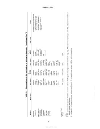
![ASME PCC-1–2010
Table
F-1
Summary
Instruction
on
the
Use
of
Alternative
Assembly
Procedures
(Cont’d)
Second
Fourth
Method
Application
First
Action
Action
Third
Action
Action
Fifth
Action
Notes
Alternative
This
bolting
pattern
only
12:00
12:00
12:00
All
bolts,
For
hard
gaskets
[Note
(2)],
a
Pattern
#3:
tightens
four
bolts
in
a
pat-
6:00
6:00
6:00
circular
minimum
of
one
pattern
pass
is
tern
to
bring
the
joint
into
3:00
3:00
3:00
pattern,
required.
CIRCULAR
alignment,
prior
to
com-
9:00
bolts
9:00
bolts
9:00
bolts
until
no
For
problematic
joints,
it
is
PATTERN
mencing
the
circular
passes.
further
nut
recommended
that
an
addi-
It
is
easy,
does
not
require
Star
pattern
Star
pattern
Star
pattern
movement
tional
pattern
pass
be
com-
the
assembler
to
mark
the
pleted
above
the
minimum
bolt
numbers,
and
requires
required.
less
effort
for
the
overall
This
procedure
has
recently
been
tightening
process.
This
approved
by
Japan’s
High
method
has
been
success-
Pressure
Institute.
Recent
analy-
fully
applied
in
limited
appli-
sis
shows
it
to
also
be
suitable
cations
across
the
harder
for
soft
materials
such
as
gaskets
[Note
(2)]
in
joint
expanded
PTFE.
configurations
commonly
found
in
refining
applications.
Percent
of
Final
Torque
20%
to
30%
50%
to
70%
100%
100%
Alternative
Eliminates
the
need
for
pat-
12:00
Split
the
Return
to
Complete
a
Purpose
of
50%
initial
tightening
Pattern
#4:
tern
passes.
At
least
four
3:00
angles
start.
circular
of
about
one-fourth
of
the
bolts
bolts
are
tightened
simulta-
6:00
between
Tighten
all
“check
is
to
ensure
parallel
alignment,
SIMULTANEOUS
neously.
Flange
alignment
is
9:00
bolts
tightened
bolts
in
pass”
mov-
seat
gasket,
and
avoid
non-
MULTIBOLT
ensured
without
the
need
bolts
until
groups
of
ing
the
four
recoverable
errors.
PATTERN
for
tightening
patterns.
It
is
approx.
four
at
tools
a
bolt
Purpose
of
splitting
the
angles
is
(4
Tools)
simpler,
does
not
require
one-fourth
90
deg
from
at
a
time
at
to
avoid
potential
“wrinkling”
of
More
than
four
the
assembler
to
mark
the
of
bolts
are
one
another
100%
until
the
gasket
or
flange.
tools
can
be
bolt
numbers
and
requires
at
50%
of
to
100%
of
no
nut
Critical
applications
may
justify
a
used,
always
less
effort.
Requires
an
auto-
final
torque
final
torque
movement
tool
on
every
bolt.
In
this
case
maintaining
matable
tightening
process,
all
bolts
should
be
tightened
even
spac-
such
as
hydraulic
torque
or
Tighten
Tighten
Tighten
Tighten
simultaneously
to
100%
of
tar-
ing
of
tools
tension.
This
method
has
four
at
a
four
at
a
four
at
at
four
at
a
get
torque.
No
check
pass
is
around
the
been
successfully
applied
in
time
time
time
time
then
required.
flange
applications
across
the
full
range
of
gaskets
and
joint
configurations
commonly
found
in
refining
and
petro-
chemical
applications.
Percent
of
Final
Torque
50%
50%
100%
100%
37
--``,``,``,```,`,``,,,`,,,````,,-`-`,,`,,`,`,,`---](https://image.slidesharecdn.com/guidelinesforpressureboundarybolted-220921120801-038ce69b/85/Guidelines-for-Pressure-Boundary-Bolted-Flange-Joint-Assembly-45-320.jpg)
![ASME PCC-1–2010
APPENDIX H
BOLT ROOT AND TENSILE STRESS AREAS
Table H-1 Bolt Root and Tensile Stress Areas
SI Units U.S. Customary Units
Bolt Size, Tensile Stress Tensile Stress
Basic Thread Designation Root Area, Area, mm2
Bolt Threads Root Area, Area, in.2
[Notes (1), (2)] mm2
[Note (3)] Size, in. per Inch in.2
[Note (3)]
M14-2 102.1 115.4 1
⁄2 13 0.1257 0.1419
M16-2 141.0 156.7 5
⁄8 11 0.2017 0.2260
M20-2.5 220.4 244.8 3
⁄4 10 0.3019 0.3345
M24-3 317.3 352.5 7
⁄8 9 0.4192 0.4617
M27-3 419.1 459.4 1 8 0.5509 0.6057
M30-3 535.0 580.4 11
⁄8 8 0.7276 0.7905
M33-3 665.1 715.6 11
⁄4 8 0.9289 0.9997
M36-3 809.3 864.9 13
⁄8 8 1.155 1.234
M39-3 976.6 1 028 11
⁄2 8 1.405 1.492
M42-3 1 140 1 206 15
⁄8 8 1.680 1.775
M45-3 1 327 1 398 13
⁄4 8 1.979 2.082
M48-3 1 527 1 604 17
⁄8 8 2.303 2.414
M52-3 1 817 1 900 2 8 2.652 2.771
M56-3 2 132 2 222 21
⁄4 8 3.422 3.557
M64-3 2 837 2 940 21
⁄2 8 4.291 4.442
M70-3 3 432 3 545 23
⁄4 8 5.258 5.425
M76-3 4 083 4 207 3 8 6.324 6.506
M82-3 4 791 4 925 31
⁄4 8 7.487 7.686
M90-3 5 822 5 970 31
⁄2 8 8.748 8.963
M95-3 6 518 6 674 33
⁄4 8 10.11 10.34
M100-3 7 253 7 418 4 8 11.57 11.81
NOTES:
(1) Metric thread designations are given in bolt size (mm) and pitch (mm) (e.g., M14-2 refers to a 14 mm diameter bolt with a 2 mm pitch
thread).
(2) The side-by-side placement of the two tables is not meant to infer direct conversion between the listed SI and U.S. Customary units.
(3) The root and tensile stress areas are based on coarse-thread series for sizes M27 and smaller, and 3 mm pitch thread series for sizes
M30 and larger (coarse-thread series for sizes 1 in. and smaller, and 8-pitch thread series for sizes 11
⁄8 in. and larger).
45
--``,``,``,```,`,``,,,`,,,````,,-`-`,,`,,`,`,,`---](https://image.slidesharecdn.com/guidelinesforpressureboundarybolted-220921120801-038ce69b/85/Guidelines-for-Pressure-Boundary-Bolted-Flange-Joint-Assembly-53-320.jpg)
![ASME PCC-1–2010
APPENDIX K
NUT FACTOR CALCULATION OF TARGET TORQUE
A common method for calculating Target Torque is
the use of the following formula:
(SI Units)
T p K D F/1 000 (K-1M)
(U.S. Customary Units)
T p K D F/12 (K-1)
where
D p nominal diameter of the bolt, mm (in.)
F p target bolt load, N (lb)
K p nut factor (see below)
T p Target Torque, N·m (ft-lb)
“K” is an experimentally determined dimensionless
constant related to the coefficient of friction. The value
of K in most applications at ambient temperature is
generally considered to be approximately equal to the
coefficient of friction plus 0.04.1
Based on the above,
friction coefficients of 0.16 and 0.12 (see Table 1M/
Table 1 of this Guideline) correspond approximately to
nut factors of 0.20 and 0.16 for noncoated and coated
bolts, respectively.
Published tables of experimental nut factors are avail-
able from a number of sources; however, care must be
taken to ensure that the factors are applicable to the
application being considered. Typical nut factors for
industrial pressure vessel and piping applications using
1
“An Introduction to the Design and Behavior of Bolted Joints,”
Bickford, p. 233.
48
SA-193 low-alloy steel bolts range from 0.16 to 0.23 at
ambient temperature. It is worthwhile to note the sensi-
tivity of obtained load to an applied torque from rela-
tively small changes in nut factor. For example, a change
from 0.1 to 0.3 does not result in a 20% change in torque,
but a 200% change. Insufficient application of lubricant
to the working surfaces will have the effect of adding
significant variability to the obtained bolt load.
It should also be noted that recent research has shown
there to be nut factor dependence on bolt material, bolt
diameter, and assembly temperature. These factors can
be significant2
and should not be ignored when selecting
the nut factor or antiseize compound. The end-user is
advised to seek test results conducted on similar bolt
and antiseize specifications or to conduct nut factor trials
with their own conditions. Nut factor trials can be con-
ducted relatively easily by tightening a bolt using torque
and measuring the obtained bolt load by calibrated
ultrasonic measurement, use of a calibrated load cell, or
measuring pressure rise on a hydraulic tensioner. In
addition, the maximum temperature listed by the manu-
facturer for a given antiseize product has been found to
not be a good indication that the product will improve
disassembly of the joint after operation at elevated tem-
perature. Once again, it is recommended that test results
on similar materials and operating conditions be sought
to guide the end-user on the appropriate product to be
employed in a given service.
2
In test results the effect of temperature was found to halve the
nut factor over the ambient temperature range often found in the
field [0°C to 40°C (32°F to 100°F)] for one antiseize product. In
addition, the nut factor has been found to increase by 30% with
SA-193 B8M bolts, by comparison to SA-193 B7 bolt material tests.
--``,``,``,```,`,``,,,`,,,````,,-`-`,,`,,`,`,,`---
标准分享网 www.bzfxw.com 免费下载](https://image.slidesharecdn.com/guidelinesforpressureboundarybolted-220921120801-038ce69b/85/Guidelines-for-Pressure-Boundary-Bolted-Flange-Joint-Assembly-56-320.jpg)
![ASME PCC-1–2010
APPENDIX M
WASHER USAGE GUIDANCE AND PURCHASE SPECIFICATION
FOR THROUGH-HARDENED WASHERS
M-1 WASHER USAGE GUIDANCE
M-1.1 Usage
The use of washers on pressure boundary bolted
flange joints is optional. However, it is generally recog-
nized that the use of through-hardened steel washers
will improve the translation of torque input into bolt
preload by providing a smooth and low friction bearing
surface for the nut.
Washers protect the contact surface of the flange from
damage caused by a turning nut. These are important
considerations when torquing methods (either manual
or hydraulic) are used for bolt tightening.
This Appendix specifies the procurement of through-
hardened washers for bolted flange joints covered within
the scope of this Guideline. The use of surface-hardened
washers is not recommended since the soft interior mate-
rial under direct compression will flow plastically, caus-
ing washer cupping and thinning with associated
reduction in preload.
M-1.2 Dimensions
The outside diameter of the washers detailed in this
Appendix was selected to enable their use on flanges
with spot faces or back facing meeting the requirements
of standard ISO 7005-1 (Metallic Flanges — Part 1: Steel
Flanges) for metric flanges and MSS SP-9 (Spot Facing
for Bronze, Iron and Steel Flanges) for inch flanges.
The inside diameter of these washers was selected to
enable their use under the nut. Use of these washers
under the head of a bolt may lead to interference with
the bolt shank or underhead fillet.
M-1.3 Service Temperature (Washer Temperature)
Service temperature limits are shown in Table M-1.
Note that in operation, actual bolting temperature
may be lower than process fluid temperature.
For uninsulated joints, ASME B31.3 (Process Piping)
considers flange bolting temperature to be 80% of fluid
temperature.
M-1.4 Existing Standards
Washers in accordance with ASTM F 436 have been
used previously on piping flanges. However, the use of
ASTM F 436 washers may lead to interference with the
spotface/backfacing on the flanges. Also, ASTM F 436
50
Table M-1 Service Temperature Limits
Material Single-Use Reuse
Type [Note (1)] [Note (2)]
1 425°C (800°F) 205°C (400°F)
4 540°C (1,000°F) 400°C (750°F)
5 650°C (1,200°F) 425°C (800°F)
6 815°C (1,500°F) 550°C (1,025°F)
NOTES:
(1) Single-use service temperature limits are based on
replacement whenever the existing washer has been exposed
to temperature in excess of the corresponding reuse limit.
(2) Reuse service temperature limits are based on metallurgical
concerns (softening) for the washer material.
does not provide dimensions for certain nominal sizes
needed for pipe or vessel flanges. The intent of the Type 1
washer in this Appendix is to specify a washer of the
same general material as an ASTM F 436 washer but
with revised dimensions to make them compatible with
pipe or vessel flanges.
M-1.5 Previous Material
Figures 1 and 2 in the original edition of PCC-1 refer-
enced ASME SA-540 for the manufacture of washers for
elevated temperature. This Appendix does not continue
the use of this material due to material cost and manufac-
turing concerns. Discontinuation of the use of SA-540
material does not imply that this material is technically
deficient.
M-1.6 Material Application
Types 1 and 4 washer materials are intended for use
with steel fasteners such as Grade 2H, 4, or 7 steel nuts
per ASME SA-194. The Type 4 washer material is an
alloy steel with higher service temperature. Types 5 and
6 washer materials are intended for use with austenitic
steel fasteners such as Grade 8 austenitic steel nuts per
ASME SA-194. The Type 6 washer material is a precipita-
tion hardening stainless steel that has increased corro-
sion resistance as compared to Type 5 washer material.
M-1.7 Installation
To avoid any concerns about the effect of washer mark-
ings on the performance of the washer to nut interface,
--``,``,``,```,`,``,,,`,,,````,,-`-`,,`,,`,`,,`---
标准分享网 www.bzfxw.com 免费下载](https://image.slidesharecdn.com/guidelinesforpressureboundarybolted-220921120801-038ce69b/85/Guidelines-for-Pressure-Boundary-Bolted-Flange-Joint-Assembly-58-320.jpg)
![ASME PCC-1–2010
Table M-2 Chemical Requirements
Composition, % [Note (1)]
Element Type 1 Type 4 [Note (2)] Type 5 [Note (3)] Type 6 [Note (4)]
Phosphorus (max.) 0.050 0.040 0.040 0.040
Sulfur (max.) 0.060 0.050 0.030 0.030
NOTES:
(1) Maximum.
(2) Type 4 low-alloy steel washers shall be manufactured from SAE number 4130 or 4140 steel listed
in ASTM A 829.
(3) Type 5 martensitic steel washers shall be manufactured from UNS S41000 steel listed in
ASME SA-240.
(4) Type 6 precipitation hardening steel washers shall be manufactured from UNS S17400 steel listed
in ASME SA-693.
Table M-3 Dimensional Requirements
for Metric Washers
O.D.
T
I.D.
Nominal Outside Diameter, Inside Diameter, Thickness,
Size, mm O.D., mm I.D., mm T, mm
14 28 15 3
16 30 17 4
20 37 21 5
24 44 25 6
27 50 28 6
30 56 31 6
33 60 34 6
36 66 37 6
39 72 42 6
42 78 45 6
45 85 48 6
48 92 52 6
52 98 56 6
56 105 62 6
64 115 70 6
70 125 76 6
76 135 82 6
82 145 88 6
90 160 96 6
95 165 101 6
100 175 107 6
GENERAL NOTE: Tolerances are as noted in Table M-5.
52
--``,``,``,```,`,``,,,`,,,````,,-`-`,,`,,`,`,,`---
标准分享网 www.bzfxw.com 免费下载](https://image.slidesharecdn.com/guidelinesforpressureboundarybolted-220921120801-038ce69b/85/Guidelines-for-Pressure-Boundary-Bolted-Flange-Joint-Assembly-60-320.jpg)
![ASME PCC-1–2010
Table M-4 Dimensional Requirements for U.S. Customary Washers
O.D.
T
I.D.
Outside Diameter,
O.D. Inside Diameter, I.D. Thickness, T
Nominal
Size, in. mm in. mm in. mm in.
1
⁄2 27.0 1.063 14.3 0.563 3.2 0.125
5
⁄8 33.4 1.313 17.5 0.688 4.0 0.156
3
⁄4 38.1 1.500 20.7 0.813 4.8 0.188
7
⁄8 43.6 1.718 23.8 0.938 5.6 0.219
1 50.0 1.968 27.0 1.063 6.4 0.250
11
⁄8 54.8 2.156 30.2 1.188 6.4 0.250
11
⁄4 60.3 2.375 33.4 1.313 6.4 0.250
13
⁄8 65.9 2.593 36.5 1.438 6.4 0.250
11
⁄2 71.4 2.812 39.7 1.563 6.4 0.250
15
⁄8 77.8 3.062 42.9 1.688 6.4 0.250
13
⁄4 82.6 3.250 46.1 1.813 6.4 0.250
17
⁄8 87.3 3.438 49.2 1.938 6.4 0.250
2 93.7 3.688 54.0 2.125 6.4 0.250
21
⁄4 104.8 4.125 60.3 2.375 6.4 0.250
21
⁄2 115.9 4.563 66.7 2.625 6.4 0.250
23
⁄4 127 5.000 73.0 2.875 6.4 0.250
3 138.1 5.438 79.4 3.125 6.4 0.250
31
⁄4 149.2 5.875 85.7 3.375 6.4 0.250
31
⁄2 160.4 6.313 92.1 3.625 6.4 0.250
33
⁄4 173.1 6.813 98.4 3.875 6.4 0.250
4 182.6 7.188 104.8 4.125 6.4 0.250
GENERAL NOTE: Tolerances are as noted in Table M-6.
Table M-5 Dimensional Tolerances for Metric Washers
14–16 mm 20–27 mm 30–42 mm 45–76 mm 82–100 mm
Dimensional Characteristics Nominal Size Nominal Size Nominal Size Nominal Size Nominal Size
Inside diameter, I.D., mm −0, +0.4 −0, +0.5 −0, +0.6 −0, +0.7 −0, +0.9
Outside diameter, O.D., mm −1.3, +0 −1.6, +0 −1.9, +0 −2.2, +0 −2.5, +0
Thickness, T, mm ±0.15 ±0.15 ±0.15 ±0.15 ±0.15
Flatness, mm (max. deviation from 0.25 0.30 0.40 0.50 0.80
straightedge placed on cut
side)
Concentricity, FIM [Note (1)], mm 0.3 0.5 0.5 0.5 0.5
(inside to outside diameters)
Burr height, mm (max. projection 0.25 0.40 0.40 0.50 0.65
above adjacent washer surface)
NOTE:
(1) Full indicator movement.
53
--``,``,``,```,`,``,,,`,,,````,,-`-`,,`,,`,`,,`---](https://image.slidesharecdn.com/guidelinesforpressureboundarybolted-220921120801-038ce69b/85/Guidelines-for-Pressure-Boundary-Bolted-Flange-Joint-Assembly-61-320.jpg)
![ASME PCC-1–2010
Table M-6 Dimensional Tolerances for U.S. Customary Washers
< 1 in. 1 through 11
⁄2 in. > 11
⁄2 through 3 in. > 3 in.
Nominal Size Nominal Size Nominal Size Nominal Size
Dimensional Characteristics mm in. mm in. mm in. mm in.
Inside diameter, I.D. −0 −0 −0 −0 −0 −0 −0 −0
+0.81 +0.032 +0.81 +0.032 +1.60 +0.063 +1.60 +0.063
Outside diameter, O.D. ±0.81 ±0.032 ±0.81 ±0.032 ±1.60 ±0.063 ±1.60 ±0.063
Thickness, T ±0.13 ±0.005 ±0.13 ±0.005 ±0.13 ±0.005 ±0.13 ±0.005
Flatness (max. deviation from 0.25 0.010 0.38 0.015 0.51 0.020 0.81 0.032
straightedge placed on cut
side)
Concentricity, FIM [Note (1)] 0.81 0.032 0.81 0.032 1.60 0.063 1.60 0.063
(inside to outside diameters)
Burr height (max. projection 0.25 0.010 0.38 0.015 0.51 0.020 0.64 0.025
above adjacent washer
surface)
NOTE:
(1) Full indicator movement.
Table M-7 Sampling
Number of Pieces in Lot Number of Specimens
800 and under 1
801 to 8,000 2
8,001 to 22,000 3
Over 22,000 5
54
--``,``,``,```,`,``,,,`,,,````,,-`-`,,`,,`,`,,`---
标准分享网 www.bzfxw.com 免费下载](https://image.slidesharecdn.com/guidelinesforpressureboundarybolted-220921120801-038ce69b/85/Guidelines-for-Pressure-Boundary-Bolted-Flange-Joint-Assembly-62-320.jpg)
![ASME PCC-1–2010
(e) From the previous points it can be seen that work-
ing and reworking the same threads in a proper installa-
tion can be beneficial.
(1) In the case of bolts with an integral head, it is
very simple to rework the same threads over and over
from assembly to assembly by simply properly installing
the same nut on the same bolt each time. Since the flange
determines the grip length (effective stretching length),
the same threads are always being worked.
(2) In the case of bolts without integral head, it is
virtually impossible to work and rework the same
threads given the current workforce practices. When it
becomes necessary to reuse bolts without integral heads,
strict control is advised to ensure that the threaded fas-
teners are correctly installed with some means of
determining that you are working the same threads. A
complete change of the nuts is also a step that may
create more uniformity.
(f) Knowing the thread friction condition of a fastener
is impossible but creating similar and fairly predictable
conditions is possible. Starting with new threaded fas-
teners and treating them all the same is the best way to
minimize load variability from bolt-to-bolt.
(g) Continuous reuse is an option when you have
adequately attended to the issues herein discussed.
(h) If an adequate bolt reuse system is used, it is
advised that the fasteners be periodically replaced based
on the following:
(1) operational fatigue or abuse, surface and/or
integral inspections, mechanical integrity inspections,
galling, nut not running freely, difficult disassembly, or
joint leakage.
(2) if one bolt in a joint is replaced, it is recom-
mended that all be replaced. If all bolts cannot be
changed, and more than one bolt is changed; space them
symmetrically around the bolt circle so that they are
surrounded by old fasteners.
(i) Tightening methods that do not apply friction
loads to the threads during the loading process such as
56
hydraulic or mechanical tensioning usually do not have
a detrimental effect on the threads due to the lack of
friction during the loading.
(j) While factors such as handling, transporting, and
storage are very important, suffice it to say that those
shall be done in a manner as to preserve both the quality
and integrity of the fastener and fastener threads.
(k) Working with and reconditioning fasteners in the
field is expensive and unpredictable when compared to
cost of new. Reconditioning/replacement considera-
tions could include
(1) number of bolts to recondition
(2) availability of new bolts
(3) labor cost
(4) criticality of the BFJ
(5) previously applied coating such as polyimide/
amide [see Notes (2) and (3) of Table 1M/Table 1]
N-3 GUIDELINES
(a) When using bolts and nuts of common grade for
fasteners up to 11
⁄8 in. diameter, the use of new bolts
and nuts is recommended when bolt load control meth-
ods such as torque or tension are deemed necessary. For
larger diameters, it is recommended that the cost of
cleaning, deburring, and reconditioning be compared to
the replacement cost and considered in the assessment
of critical issues of the assembly.
(b) Strong consideration should be given to replacing
bolts of any size should it be found that they have been
abused or nonlubricated during previous assemblies.
(c) Thread dies generally do not yield a highly cleaned
reconditioned surface; therefore, turning bolt threads in
a lathe is the preferred method to recondition costly
fasteners. Although preferred, this process will remove
thread material and tolerance limits specified in
ASME B1.1 must be maintained.
(d) Nuts are not generally reconditioned.
--``,``,``,```,`,``,,,`,,,````,,-`-`,,`,,`,`,,`---
标准分享网 www.bzfxw.com 免费下载](https://image.slidesharecdn.com/guidelinesforpressureboundarybolted-220921120801-038ce69b/85/Guidelines-for-Pressure-Boundary-Bolted-Flange-Joint-Assembly-64-320.jpg)
![ASME PCC-1–2010
APPENDIX O
ASSEMBLY BOLT STRESS DETERMINATION
O-1 INTRODUCTION
O-1.1 Scope
The intent of this Appendix is to provide guidance
for the determination of an appropriate assembly bolt
stress with due consideration for joint integrity. The
detailed procedures provided in this Appendix are
intended for flange joints for which controlled assembly
methods are to be used. Provisions are made for both a
simple approach and for a joint component approach.
O-1.2 Cautions
The provisions of this Appendix consider that the
PCC-1 guidelines for the joint component condition
(flange surface finish, bolt spacing, flange rigidity, bolt
condition, etc.) are within acceptable limits.
The methodology outlined below assumes that the
gaskets being used undergo a reasonable amount (>15%)
of relaxation during the initial stages of operation, such
that the effects of operational loads in increasing the
bolt stress need not be considered (i.e., gasket relaxation
will exceed any operational bolt load increase). In some
rare cases, this may not be the case, and the limits should
then also be checked at both the ambient and operating
bolt stress and temperatures. For most standard applica-
tions, this will not be necessary.
In addition, the methodology is for ductile materials
(strain at tensile failure in excess of 15%). For brittle
materials, the margin between the specified assembly
bolt stress and the point of component failure may be
considerably reduced and, therefore, additional safety
factors should be introduced to guard against such
failure.
The method does not consider the effect of fatigue,
creep, or environmental damage mechanisms on either
the bolt or flange. These additional modes of failure may
also need to be considered for applications where they
are found and additional reductions in assembly bolt
stress may be required to avoid joint component failure.
O-1.3 Definitions
Ab p bolt root area, mm2
(in.2
)
Ag p gasket area [/4 (GO.D.
2
− GI.D.
2
)], mm2
(in.2
)1
1
Where a gasket has additional gasket area, such as a pass parti-
tion gasket, which may not be as compressed as the main outer
sealing element, due to flange rotation, then a reduced portion of
that area, such as half the additional area, should be added to Ag.
57
GI.D., GO.D. p gasket sealing element inner/outer
diameter, mm (in.)
K p nut factor (for bolt material and
temperature)
nb p number of bolts
Pmax p maximum design pressure, MPa (psi)
Sya p flange yield stress at assembly, MPa
(psi)
Syo p flange yield stress at operation, MPa
(psi)
Sbmax p maximum permissible bolt stress,
MPa (psi)
Sbmin p minimum permissible bolt stress,
MPa (psi)
Sbsel p selected assembly bolt stress, MPa (psi)
Sfmax p maximum permissible bolt stress prior
to flange damage, MPa (psi)
SgT p target assembly gasket stress, MPa
(psi)
Sgmax p maximum permissible gasket stress,
MPa (psi)
Sgmin-S p minimum gasket seating stress, MPa
(psi)
Sgmin-O p minimum gasket operating stress,
MPa (psi)
Tb p assembly bolt torque, N·m (ft-lb)
b p bolt diameter, mm (in.)
fmax p sum of flange rotations at Sfmax, deg
gmax p maximum permissible flange rotation
for gasket at the maximum operating
temperature, deg
g p fraction of gasket load remaining after
relaxation
O-2 ASSEMBLY BOLT STRESS SELECTION
It is recommended that bolt assembly stresses be
established with due consideration of the following joint
integrity issues.
(a) Sufficient Gasket Stress to Seal the Joint. The assem-
bly bolt stress should provide sufficient gasket stress
to seat the gasket and sufficient gasket stress during
operation to maintain a seal.
(b) Damage to the Gasket. The assembly bolt stress
should not be high enough to cause over-compression
(physical damage) of the gasket or excessive flange rota-
tion of the flange, which can also lead to localized gasket
over-compression.
--``,``,``,```,`,``,,,`,,,````,,-`-`,,`,,`,`,,`---](https://image.slidesharecdn.com/guidelinesforpressureboundarybolted-220921120801-038ce69b/85/Guidelines-for-Pressure-Boundary-Bolted-Flange-Joint-Assembly-65-320.jpg)
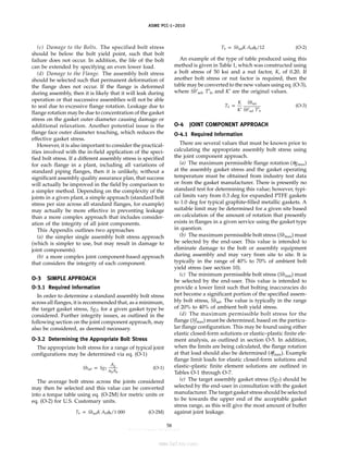
![ASME PCC-1–2010
(f) The maximum assembly gasket stress (Sgmax) must
be obtained from industry test data or from the gasket
manufacturer. This value is the maximum compressive
stress at the assembly temperature, based on full gasket
area, which the gasket can withstand without permanent
damage (excessive leakage or lack of elastic recovery) to
the gasket sealing element. Any value provided should
include consideration of the effects of flange rotation
for the type of flange being considered in increasing the
gasket stress locally on the outer diameter.
(g) The minimum gasket seating stress (Sgmin-S) must
be obtained from industry test data or from the gasket
manufacturer. This value is the minimum recommended
compressive stress at the assembly temperature and is
based on full gasket area. The value is the stress that
the gasket should be assembled to in order to obtain
adequate redistribution of any filler materials and
ensure an initial seal between the gasket and the
flange faces.
(h) The minimum gasket operating stress (Sgmin-O)
must be obtained from industry test data or from the
gasket manufacturer. This value is the minimum recom-
mended compressive stress during operation and is
based on full gasket area. This is the gasket stress that
should be maintained on the gasket during operation
in order to ensure the leakage does not occur.
(i) The gasket relaxation fraction (g) must also be
obtained from industry test data or from the gasket
manufacturer for the gasket in flange assemblies of simi-
lar configuration to the ones being assessed. A default
value of 0.7 may be used if data are not available.
O-4.2 Determining the Appropriate Bolt Stress
Once the limits are defined, it is possible to utilize
the following process for each joint configuration. This
process can be performed using a spreadsheet or soft-
ware program, which allows the determination of many
values simultaneously.
Step 1: Determine the target bolt stress in accordance
with eq. (O-1).
Step 2: Determine if the bolt upper limit controls
Sbsel p min. (Sbsel, Sbmax) (O-4)
Step 3: Determine if the bolt lower limit controls
Sbsel p max. (Sbsel, Sbmin) (O-5)
59
Step 4: Determine if the flange limit controls2
Sbsel p min. (Sbsel, Sfmax) (O-6)
Step 5: Check if the gasket assembly seating stress is
achieved.
Sbsel ≥ Sgmin-S [Ag/(Abnb)] (O-7)
Step 6: Check if the gasket operating stress is
maintained.3
Sbsel ≥ (Sgmin-O Ag + /4PmaxGI.D.
2
)/(gAbnb) (O-8)
Step 7: Check if the gasket maximum stress is
exceeded.
Sbsel ≤ Sgmax [Ag/(Abnb)] (O-9)
Step 8: Check if the flange rotation limit is exceeded.
Sbsel ≤ Sfmax (gmax/fmax) (O-10)
If one of the final checks (Steps 5 through 8) is
exceeded, then judgment should be used to determine
which controlling limit is more critical to integrity and,
therefore, what the selected bolt load ought to be. A
table of assembly bolt torque values can then be calcu-
lated using eq. (O-2M) or (O-2). An example table of
assembly bolt stresses and torque values using this
approach is outlined in Tables O-8 and O-9, respectively.
O-4.3 Example Calculation
NPS 3 Class 300 Flange Operating at Ambient
Temperature (Identical Limits Used as Those in
Table O-8) with nut factor per Table O-9
Ab p 0.3019 in.2
nb p 8
AbWnb p 2.42 in.2
Ag p 5.17 in.2
b p 0.75 in.
Pmax. p 750 psig (0.75 ksi)
g p 0.7
GI.D. p 4.19 in.
2
In some cases (e.g., high temperature stainless steel flanges)
the yield strength of the flange may reduce significantly during
operation. In those cases, the flange limit should be reduced by
the ratio of the yields (Sfmax Syo/Sya). A useful ratio for determining
if this adjustment must be performed is to compare the reduction
in yield to the amount of relaxation occurring and if the reduction
ratio exceeds the relaxation, the effect should be included. This
check is expressed as follows: the reduction factor should be
included if (1 − Syo/Sya) > 1.25g. The additional reduction in gasket
relaxation (1.25 term) is included to capture possible variances in
actual relaxation versus test or assumed values.
3
Note that this simple treatment does not take into account the
changes in bolt load during operation due to component elastic
interaction. A more complex relationship for the operational gasket
stress may be used in lieu of this equation that includes the effects
of elastic interaction in changing the bolt stress.
--``,``,``,```,`,``,,,`,,,````,,-`-`,,`,,`,`,,`---](https://image.slidesharecdn.com/guidelinesforpressureboundarybolted-220921120801-038ce69b/85/Guidelines-for-Pressure-Boundary-Bolted-Flange-Joint-Assembly-67-320.jpg)
![ASME PCC-1–2010
Determine Bolt Stress:
Equation (O-1): Sbsel p 30.(5.17/2.42) p 64 ksi
Equation (O-4): Sbsel p min. (64, 75) p 64 ksi
Equation (O-5): Sbsel p max. (64, 35) p 64 ksi
Table O-2: Sfmax p 63 ksi (note: Syo p Sya)
Equation (O-6): Sbsel p min. (64, 63) p 63 ksi
Additional Checks:
Equation (O-7): Sbsel ≥ 12.5 (5.17/2.42) ≥ 26.7 ksi ✓
Equation (O-8): Sbsel ≥ (6.0 ⴛ 5.17 + /4 ⴛ 0.75 ⴛ
4.192
)/(0.7 ⴛ 2.42) ≥ 24 ksi ✓
Equation (O-9): Sbsel ≤ 40 (5.17/2.42) ≤ 85 ksi ✓
Table O-4: fmax p 0.32 deg
Equation (O-10): Sbsel ≤ 63 (1.0/0.32) ≤ 197 ksi ✓
Equation (O-2): Tb p 63,000 ⴛ 0.2 ⴛ 0.3019 ⴛ
0.75/12
Tb ≈ 240 ft-lb
Note that for some flanges (NPS 8, class 150 for exam-
ple) the additional limits [eq. (O-7) onward] are not
satisfied. In those cases, engineering judgment should
be used to determine which limits are more critical to the
joint integrity, and the value of Sbsel should be modified
accordingly. It should be noted that the values presented
are not hard limits (i.e., flange leakage will not occur if
the gasket stress falls 0.1 psi below the limit) and there-
fore some leeway in using the values is to be considered
normal.
60
O-5 DETERMINING FLANGE LIMITS
O-5.1 Elastic Analysis
A series of elastic analysis limits have been deter-
mined that allow the calculation of the approximate
assembly bolt stress that will cause significant perma-
nent deformation of the flange. Since this bolt stress is
approximate, and the flange material yield tends to be
lower bound, it is considered appropriate to use these
limits without modification or additional safety factor.
An explanation of the limits and equations used to deter-
mine the bolt stress can be found in WRC Bulletin 528.
O-5.2 Finite Element Analysis
A more accurate approach to determining the appro-
priate limit on assembly bolt load is to analyze the joint
using elastic–plastic nonlinear Finite Element Analysis
(FEA). An explanation of the requirements for per-
forming such an analysis are outlined in WRC Bulletin
528. It is not necessary to rerun the analysis for minor
changes to the joint configuration (such as different gas-
ket dimensions or minor changes to the flange material
yield strength) as linear interpolation using the ratio of
the change in gasket moment arm or ratio of the different
yield strength can be used to estimate the assembly bolt
stress limit for the new case.
--``,``,``,```,`,``,,,`,,,````,,-`-`,,`,,`,`,,`---
标准分享网 www.bzfxw.com 免费下载](https://image.slidesharecdn.com/guidelinesforpressureboundarybolted-220921120801-038ce69b/85/Guidelines-for-Pressure-Boundary-Bolted-Flange-Joint-Assembly-68-320.jpg)
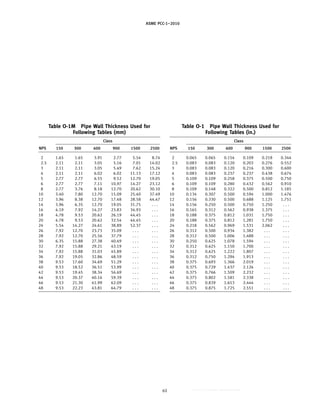
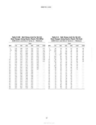
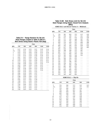
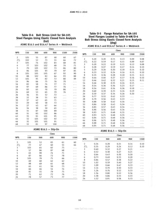
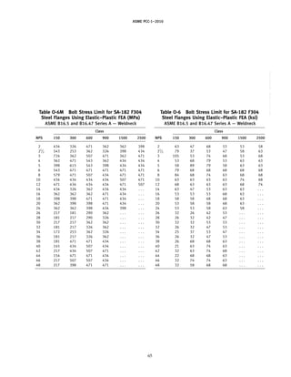
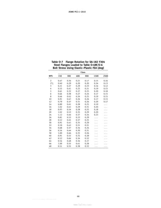
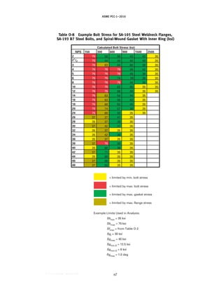
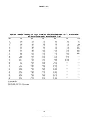
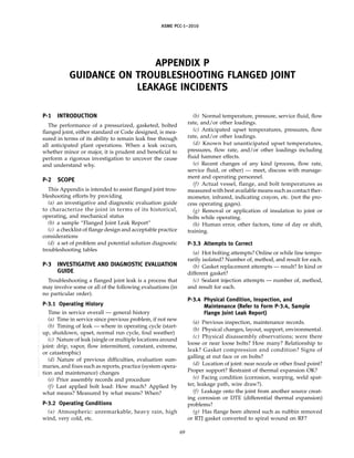
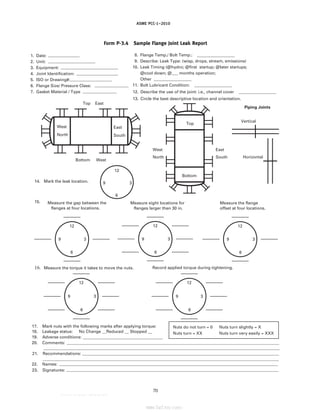
![ASME PCC-1–2010
(h) Is the flange within minimum thickness require-
ments? (Check flanged joint standard or Code
calculation.)
(i) Flange alignment measurements — current and
previous?
(j) Support (or lack of) for external loadings (weight
or thermal).
(k) Are the bolts and/or flanges insulated? Condition
of insulation? Condition of portable pads (removable
insulation pads)?
(l) Same effective length for all bolts? Example of
different effective lengths would be a heat exchanger
tubesheet joint where the tubesheet has some but not
all holes threaded for retaining the tubesheet to shell seal
when removing the channel for inspection and cleaning.
The threaded tubesheet creates a different effective bolt
length as it functions as a nut in the middle of the bolt.
Refer to P-4.2.
P-3.5 Previous Assembly Practices
(a) Assembler qualifications, training.
(b) Assembly procedures and/or PCC-1
conformance.
(c) Assembler access — i.e., poor tool access, ineffec-
tive staging, nut socket fit, etc.
(d) Ability to access the joint to perform the assembly.
Assembly tooling employed.
P-3.6 Specifications Conformance
(a) Gasket
(b) Hardware (bolts/studs, nuts, washers), (were
washers through-hardened?), flanges.
(c) Conformance of support arrangements (or lack of)
for external loads (weight, dynamic or thermal), and
piping thermal expansion restraint arrangement.
P-4 CHECKLIST OF FLANGE DESIGN AND
ACCEPTABLE PRACTICE CONSIDERATIONS
A well assembled joint cannot function as intended,
and the correct clamping force cannot be created if the
design, the specification, or the fabrication, including
the gasket, are faulty. Because of the interactions, inter-
dependencies, and interrelationships that are inherent
in a bolted joint assembly, the performance of a properly
assembled bolted joint assembly is contingent upon
many choices made and activities performed within
acceptable limits.
The design and practice checklist below is a tool
intended to assist the troubleshooter in spotting poten-
tial problems associated with a particular joint. It applies
to both standard piping joints and Code designed
flanged joints (as noted) that have experienced chronic
leakage.
71
P-4.1 Loading Effects
Often a flanged joint is designed (or selected) for inter-
nal system pressure loadings only, whereas in reality
significant external forces, pressure surge, and thermal
loadings may occur and affect the gasket load and joint
tightness.
P-4.1.1 External Bending or Axial Force
(a) Review design documents and calculations for any
specified additional forces and compare these with cur-
rent operating circumstances. Consider the reactions of
piping systems against nozzles and vessel joints.
(b) Review against design documents the actual pip-
ing system layout, support, guides, and constraints for
sources of unanticipated bending or axial forces. Con-
sider the effect of unintended restraint of piping thermal
expansion in terms of forces and bending moments.
(c) Evaluate the effect of external loads on the joint.
Reference [1] and its references provide methodology
for the evaluation of external loadings on pressurized
flanged joints. Public computer programs exist that are
fully capable of evaluating external loadings on flanged
joints.
(d) Although not specifically referenced in
Appendix 2 of Section VIII, Division 1 of the Boiler and
Pressure Vessel Code, the requirement that all loads be
considered is covered in Code para. UG-22 which, if
considered, will diminish the likelihood of leakage.
P-4.1.2 Differential Thermal Expansion (DTE). Differ-
ential thermal expansion between the bolts and flanges
is present in all joints operating at non-ambient tempera-
tures. Both axial and radial effects on flange components
must be considered. Generally, when the coefficients of
expansion of flanges and bolting are closely matched,
properly assembled joints with an operating fluid tem-
perature less than about 260°C (500°F) should withstand
normal start-ups and shutdowns.
P-4.1.3 Pressure Surge. Flanged joints within sys-
tems subject to pressure surge should be reviewed to
ascertain the consistency of restraints and anchors for
both DTE and surge loads.
P-4.2 Joint Flexibility Issues
Generally speaking, strong and long bolts provide for
more flexible joints as will a joint with two flanges as
opposed to a single flange joint. A more flexible joint
will withstand more abuse such as DTE loads. Stronger
bolts also permit higher assembly loads if needed.
P-4.2.1 Single Flange Joints. Flange joints con-
sisting of a single flange with bolts threaded into tapped
holes are inherently less flexible and generally more
troublesome because they are less tolerant of gasket
thickness loss, or relaxation, and DTE effects because of
the shorter effective stretching length of the bolts. Such
joints are roughly twice as stiff as a normal two-flange
--``,``,``,```,`,``,,,`,,,````,,-`-`,,`,,`,`,,`---](https://image.slidesharecdn.com/guidelinesforpressureboundarybolted-220921120801-038ce69b/85/Guidelines-for-Pressure-Boundary-Bolted-Flange-Joint-Assembly-79-320.jpg)
![ASME PCC-1–2010
joint of the same size and rating and therefore will suffer
roughly twice the bolt load loss for each 0.001 in. loss
of gasket thickness (post assembly).
P-4.2.2 Increasing Bolt Flexibility. Consider increas-
ing bolt flexibility with extension collars and longer bolts
to increase effective length if necessary. (Effective
stretching length is normally calculated as the distance
between nut contact faces plus one bolt diameter.)
P-4.2.3 Flange Rigidity. Flange rigidity should meet
ASME Code requirements for best joint performance
[see para. 2-14(a) of Section VIII, Division 1] unless
acceptable successful experience indicates otherwise.
Consider the addition of split backing rings to increase
rigidity for existing flanges to limit excessive flange
rotation.
P-4.3 Bolting Material Considerations
(a) If yielding of low strength bolts is evident (or pre-
dictable by computation), the use of high strength bolt-
ing to allow a greater target bolt prestress should be
considered. For example, SA-193 B7, SA-193 B16, SB-637
(Alloy N07718), etc.
(b) Match coefficients of expansion of flange and bolt-
ing as closely as possible (see P-4.1.2).
(c) Employ and design for high strength bolting [e.g.,
SA-193 B7, SA-193 B16, SB-637 (Alloy N07718), etc.], to
allow 345 MPa (50 ksi) or greater target bolt prestress.
(d) If stainless steel bolting is required, SA-453 Grade
660 is the best choice since it has the strength properties
to allow a 345 MPa (50 ksi) target bolt prestress.
(e) Avoid use of low-strength SA-193 B8 Class 1 stain-
less steel bolts. These will most likely result in unaccept-
ably low assembly loads. Strain-hardened SA-193 B8
Class 2 bolts will provide better results.
P-4.4 Bolt Spacing Considerations
(a) Check minimum bolt spacing based on wrench
clearance considerations to confirm accessibility.
(b) Low gasket stress can result from excessive bolt
spacing. Bolt spacing for non-standard flanges should
normally not exceed 2 times bolt diameter plus 6ⴛ the
flange thickness divided by the quantity (m + 0.5), where
m is the Section VIII, Division 1, Appendix 2 gasket
factor. Use m p Smo/pressure where tightness based
gasket constants are used as in References [2] and [3].
P-4.5 Gasket Considerations
P-4.5.1 Gasket Selection
(a) Spiral-wound gaskets in nominal sizes greater
than 600 mm (24 in.) are fragile and must be carefully
handled. Consider an inner ring.
(b) Avoid double-jacketed gaskets, regardless of the
filler material, for joints subjected to differential radial
movement of the flanges, such as in shell and tube
exchanger girth joints.
72
Fig. P-1 Tapered Hub Type Flange
X
A
B Y
tf
O
Welding Neck
(c) As an exception to (b) for male/female facings,
consider use of 3-ply corrugated metal style gasket with
0.4 mm (0.015 in.) thick expanded graphite adhesive-
backed tape on both sides for sizes greater than NPS 24.
A 0.8 mm (1
⁄32 in.) thick center ply will improve the
gasket elastic recovery characteristic.
(d) Check adequacy of gasket stress under the antici-
pated or specified bolt prestress.
(e) Gasket Width Selection — Normally use 16 mm
(5
⁄8 in.) or wider gaskets. Use widths in the range of
25 mm to 38 mm (1.0 in. to 1.5 in.).
P-4.5.2 Gasket Location and Contact Surface
(a) Check if gasket contact surface location is as close
as practicable to the bolt circle (e.g., minimize hG dimen-
sion) to reduce flange rotation effects at seating surface.
(b) Gasket contact surface finish should be in range
of 3.2 m to 6.3 m (125 in. to 250 in.) for most
nonpiping applications. Follow ASME B16.5 for piping
flange finishes.
(c) Radial scratches deeper than the surface finish
should be repaired. (Refer to Appendix D.)
(d) The use of nubbins is not generally accepted good
engineering practice regardless of gasket type. Nubbins
should be removed if differential radial movement of
flanges occurs or is evidenced by inspection of facing
surfaces.
(e) The use of male/female or tongue and groove
facing to ensure proper gasket centering avoids work-
manship issues.
P-4.6 Flange Type Selection Considerations
P-4.6.1 Tapered Hub Type Flange (See Fig. P-1)
(a) Provides most favorable transition of stress
through the tapered hub from the flange thickness to
the shell thickness, a consideration favorable for services
for which fatigue and brittle fracture avoidance are gov-
erning design requirements.
(b) Allows butt-welded attachment to the shell
(Category C location).
(c) Allows radiographic examination of the
Category C butt joint.
--``,``,``,```,`,``,,,`,,,````,,-`-`,,`,,`,`,,`---
标准分享网 www.bzfxw.com 免费下载](https://image.slidesharecdn.com/guidelinesforpressureboundarybolted-220921120801-038ce69b/85/Guidelines-for-Pressure-Boundary-Bolted-Flange-Joint-Assembly-80-320.jpg)
![ASME PCC-1–2010
Fig. P-2 Slip-on Type Flange
X
B
Y
tf
O
Slip-on Welding
(d) Provides the most flange rigidity for a given flange
thickness.
(e) Suitable for lethal service application.
P-4.6.2 Slip-On Type Flanges (See Fig. P-2)
(a) Not to be used for lethal service application
(Section VIII, Division 1 Code requirement).
(b) Is double fillet welded to shell, thereby limiting
the nondestructive examination to either MT or PT.
(c) The abrupt transition of stress from the flange (or
flange hub) thickness to the shell via a fillet weld is
not favorable to services for which fatigue and brittle
fracture avoidance are governing design requirements.
(d) Pocket formed by face welds in a companion joint
may create a liquid pool and unequal thermal stresses
with resultant temporary leakage during heat-up cycle.
(e) Good practices that have evolved over time
regarding the use of slip-on type flanges are to
(1) limit use to design temperatures not exceeding
343°C (650°F).
(2) limit use of carbon or low-alloy steel flanges to
solid high-alloy shells to design temperatures no higher
than 232°C (450°F), unless a higher temperature is justi-
fied by a complete stress analysis and accepted by the
user or his designated agent.
(3) provide small [DN 6 (NPS 1
⁄8)] vent through hub
prior to assembly.
(4) avoid for services subject to moderate corrosion
such as to require a corrosion allowance in excess of
1.5 mm (1
⁄16 in.); consider face-weld leakage and resultant
hidden corrosion in crevice between flange I.D. and
shell.
(5) avoid use in hot hydrogen service [defined for
carbon steel as a hydrogen partial pressure exceeding
100 psia with a corresponding coincident temperature
exceeding 200°C (400°F)], or other suitable user, API, or
PIP defined hydrogen service limits.
P-4.6.3 Lap Joint Flange (See Fig. P-3)
(a) Allows use of high strength, carbon, or low-alloy
steel flange material in services where expensive
high-alloy pressure-boundary materials are required.
73
Fig. P-3 Lap Joint Flange
Lap Joint
(b) Allows use of closely matching coefficients of
expansion of flange materials as described above with
high-strength bolting such as SA-193-B7, SA-193-B16,
SB-637 (Alloy N07718), etc.
(c) Superior flange style when the joint will be sub-
jected to rapid heat-up/cooldown temperature cycles.
This is because lap joint flanges do not experience the
discontinuity forces and moments created during a ther-
mal cycle in the tapered hub-type flange which result
in an unwanted flange rotation cycle. Additionally, the
lap-joint flange is not in intimate contact with the service
fluid and hence the heating/cooling rate of the flange
assembly is retarded relative to service-fluid changes,
thereby minimizing the unwanted temperature differen-
tials between the flange and bolts.
(d) Suitable for lethal service application provided
the Category C joint for lap joint stub end meets the
requirement of para. UW-2 of the Section VIII, Division 1
Code.
P-4.6.4 Use of Lap Joint Flanges. Good practices
that have evolved over time regarding the use of lap
joint flanges are to
(a) require a finished lap ring thickness to be a mini-
mum of 5 mm (3
⁄16 in.) greater than the nominal wall
thickness of the shell.
(b) require that the laps be machined front and back
as required to provide parallel surfaces and surfaces
normal to the axis of the shell after all fabrication is
complete.
(c) provide lap type flange-to-shell clearance of 3 mm
(1
⁄8 in.) for nominal diameters up to and including
1 000 mm (40 in.) and 5 mm (3
⁄16 in.) for larger nominal
diameters.
(d) Configure the gasket/lap/flange design so that
the gasket load reaction on the lap (defined as G in
Appendix 2 of Section VIII, Division 1) is as close as
practicable to being coincident with the reaction of the
flange against the back of the lap (taken as the midpoint
of contact between the flange and lap).
--``,``,``,```,`,``,,,`,,,````,,-`-`,,`,,`,`,,`---](https://image.slidesharecdn.com/guidelinesforpressureboundarybolted-220921120801-038ce69b/85/Guidelines-for-Pressure-Boundary-Bolted-Flange-Joint-Assembly-81-320.jpg)
![ASME PCC-1–2010
Recommended radial lap widths are as follows:
Nozzle/Vessel O.D., mm (in.) Radial Lap Width, mm (in.)
O.D. ≤ 457 (18) 25 (1.00)
457 (18) < O.D. ≤ 914 (36) 38 (1.50)
914 (36) < O.D. ≤ 1 523 (60) 45 (1.75)
O.D. > 1 523 (60) 50 (2.00)
GENERAL NOTES:
(a) Radial lap width is measured from the toe of the lap-to-shell
attachment weld to the outer edge of the lap ring.
(b) Provide a minimum of four lugs on the shell for each lap joint
flange to permit the joint to be pried apart for removing and
replacing the gasket. The lugs for the lowermost flange in a
joint for which the flange ring is in a horizontal plane will also
support the flange when the joint is disassembled.
P-5 Leakage Problems and Potential Solutions
This section provides a series of diagnostic tables with
each dedicated to a specific type of leak event. These are
LHT: Leak during hydro-test (see Table P-1)
74
LIO: Leak during heat-up or initial operation (see
Table P-2)
LCU: Leak corresponding to thermal or pressure upset
(see Table P-3)
LTO: Leak after several months operation — piping (see
Table P-4)
LDS: Leak during shut down (see Table P-5)
P-6 REFERENCES
[1] Koves, W. J., “Design for Leakage in Flange Joints
Under External Loads,” ASME PVP Proceedings, Paper
PVP2005-71254, July 2005
[2] Payne, J. R., “On The Operating Tightness Of B16.5
Flanged Joints,” ASME PVP Proceedings, Paper
PVP2008-61561, July 2008
[3] Bickford, J. H., “An Introduction to the Design and
Behavior of Bolted Joints,” Chapter 19, CRC Press, 1995
--``,``,``,```,`,``,,,`,,,````,,-`-`,,`,,`,`,,`---
标准分享网 www.bzfxw.com 免费下载](https://image.slidesharecdn.com/guidelinesforpressureboundarybolted-220921120801-038ce69b/85/Guidelines-for-Pressure-Boundary-Bolted-Flange-Joint-Assembly-82-320.jpg)
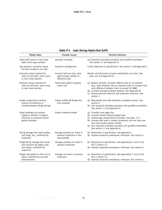
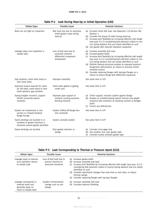
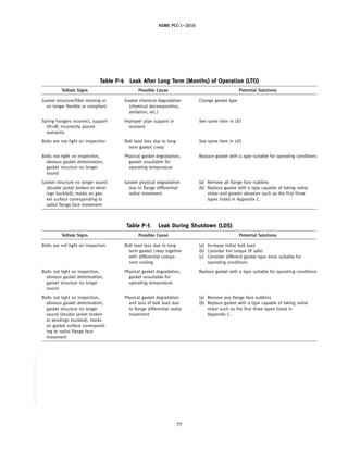


The document establishes guidelines for the assembly of pressure boundary bolted flange joints as defined in ASME PCC-1–2010. It outlines various processes such as training, cleaning, installation, alignment, tightening, and disassembly of joints, emphasizing good practices and responsibilities for users. The standard was developed following accredited procedures and includes references for further guidance in pressure equipment maintenance and integrity management.


