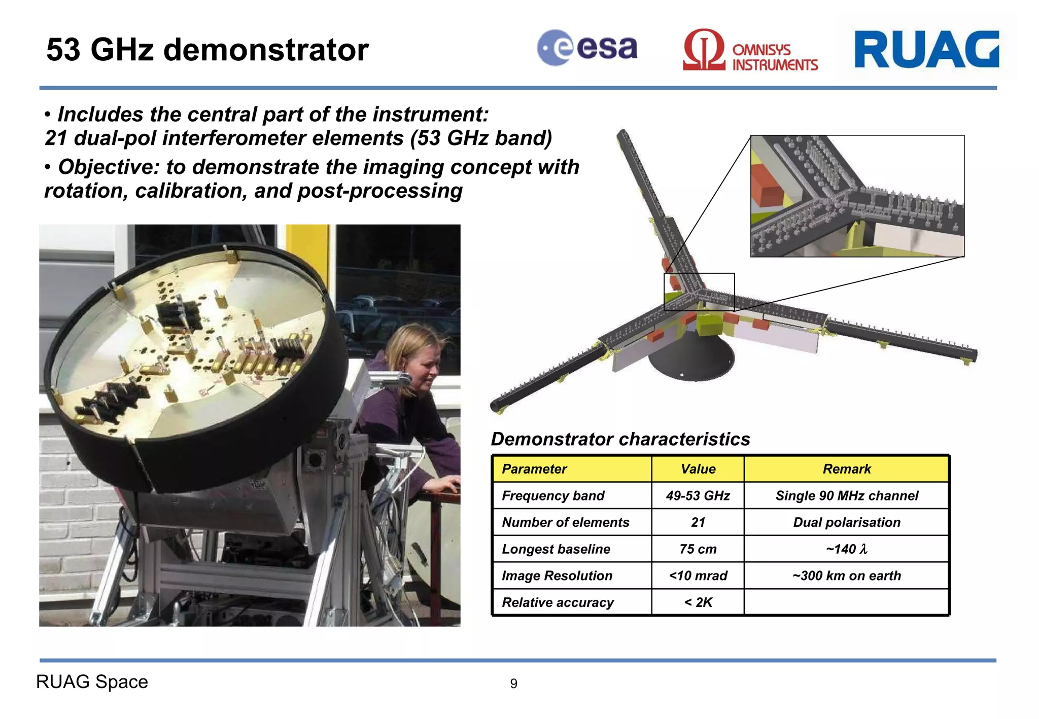
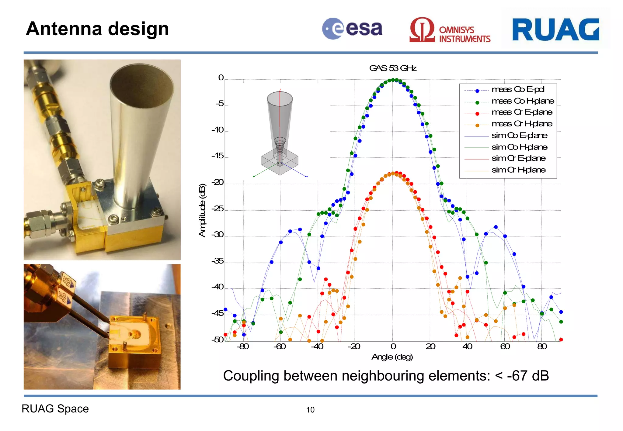
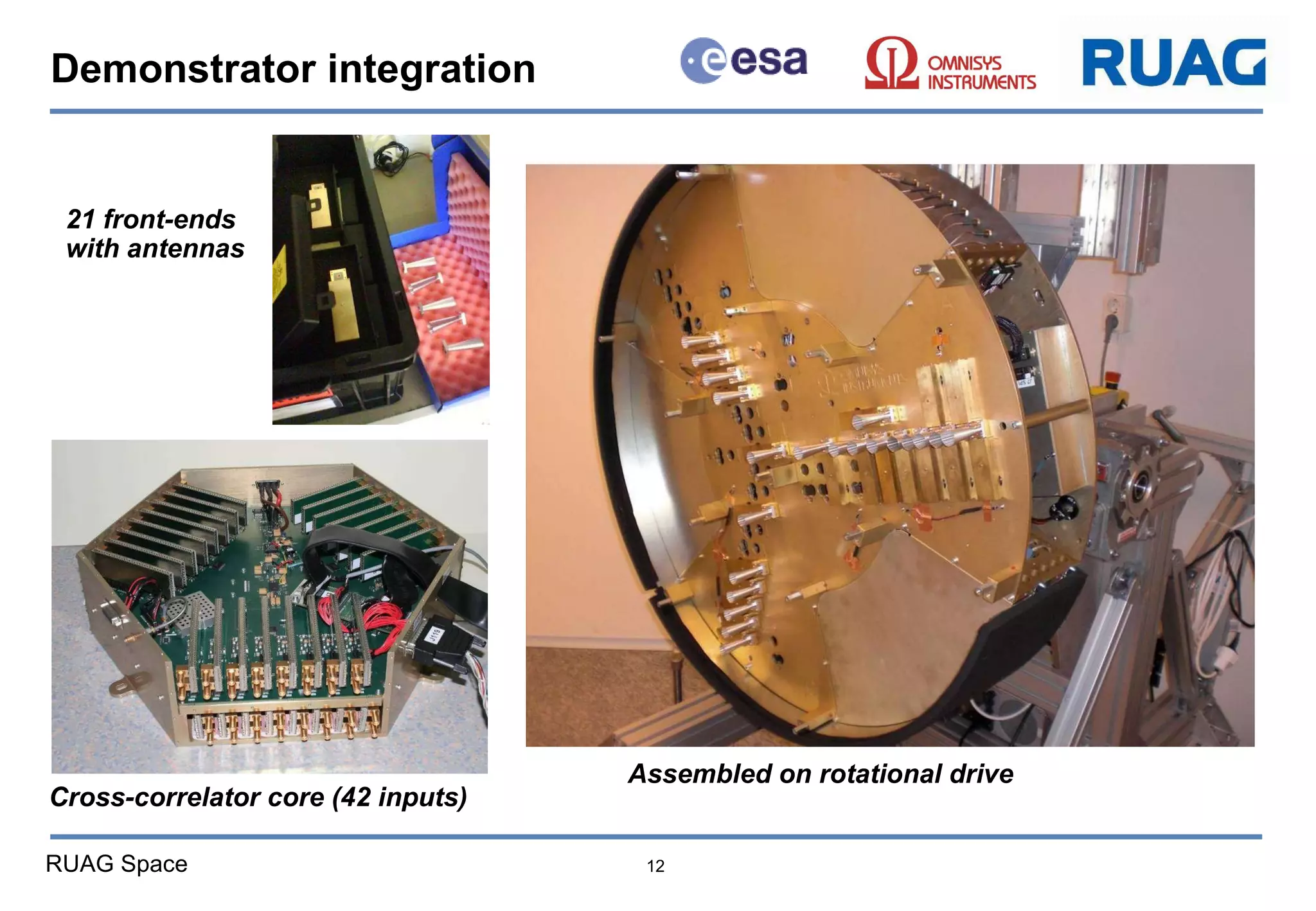
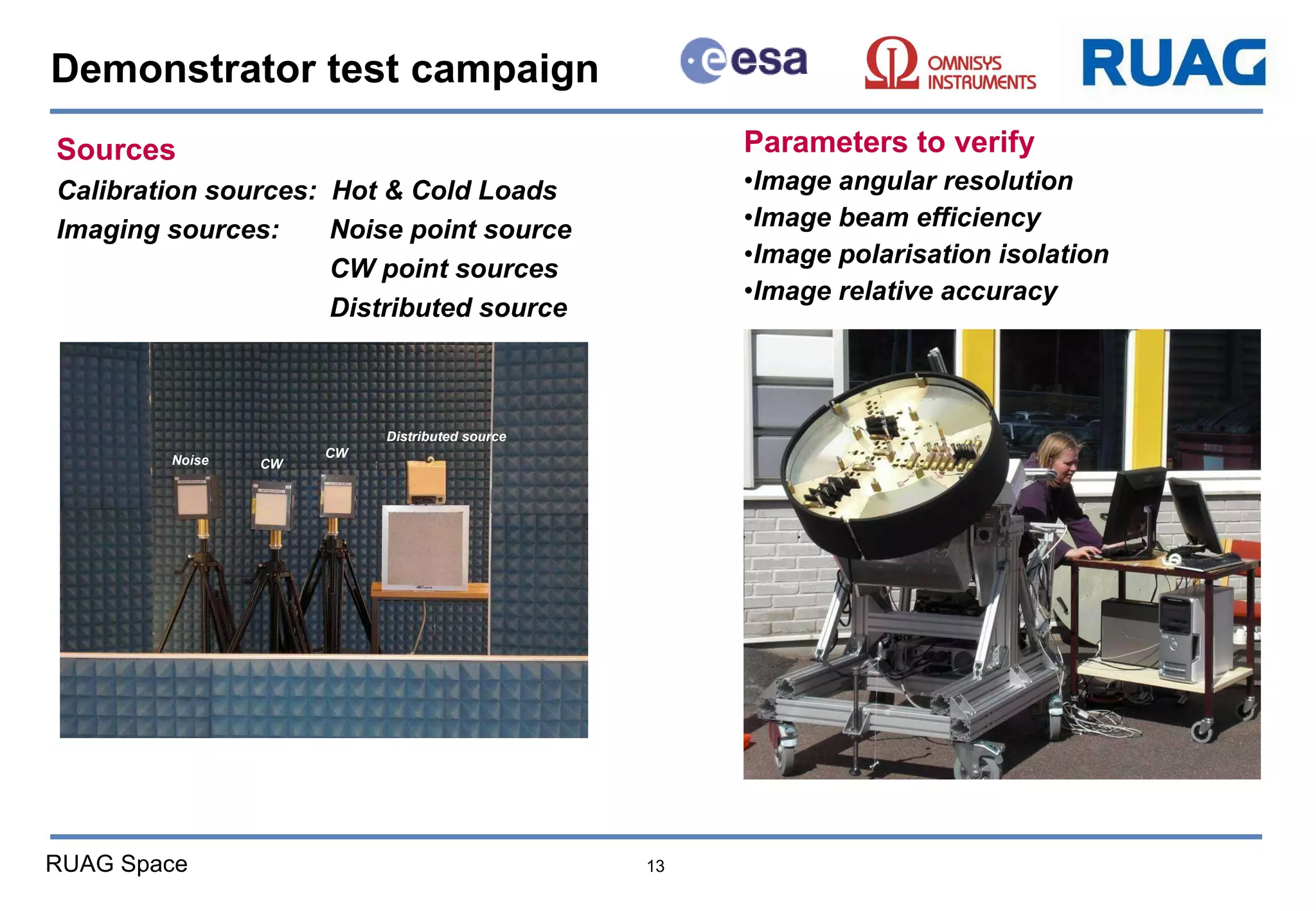
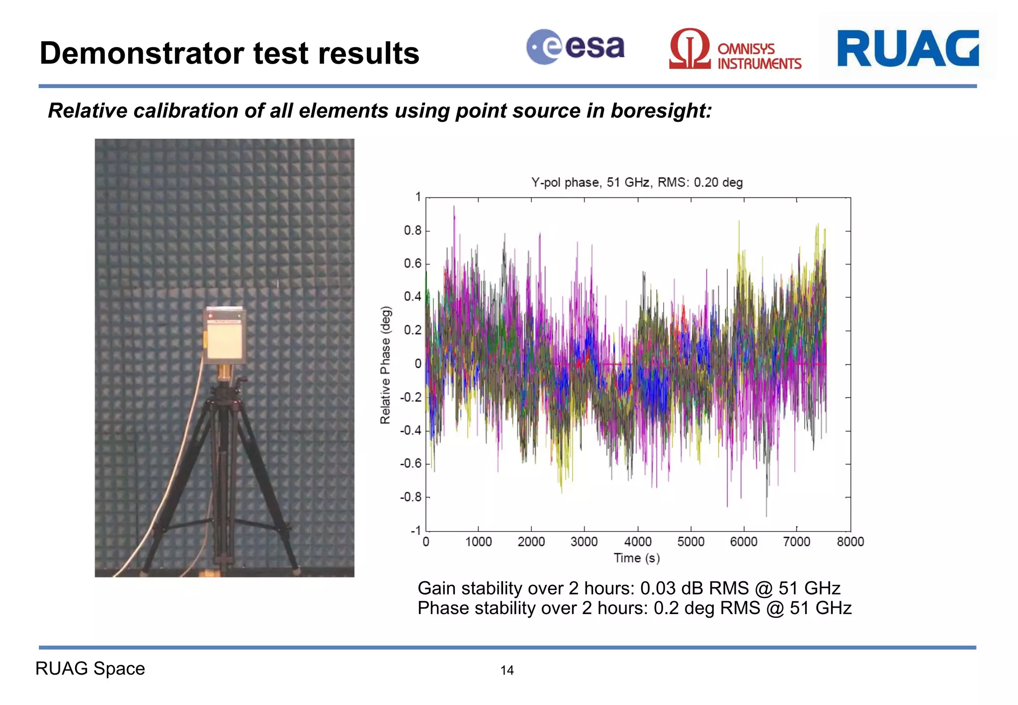
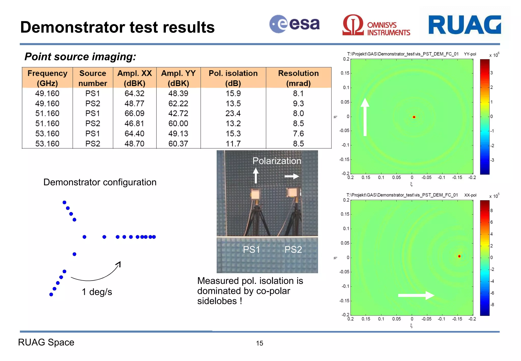
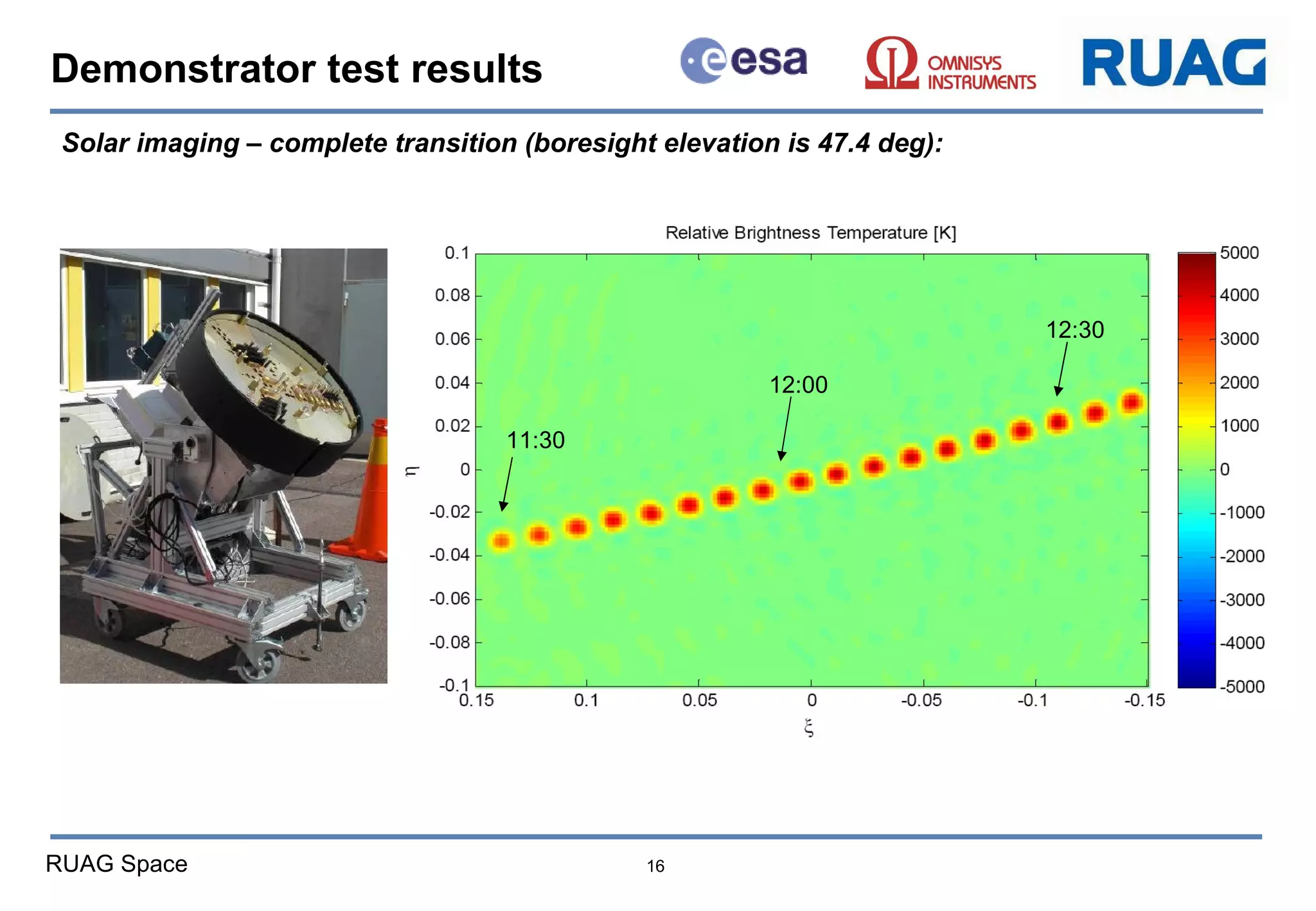
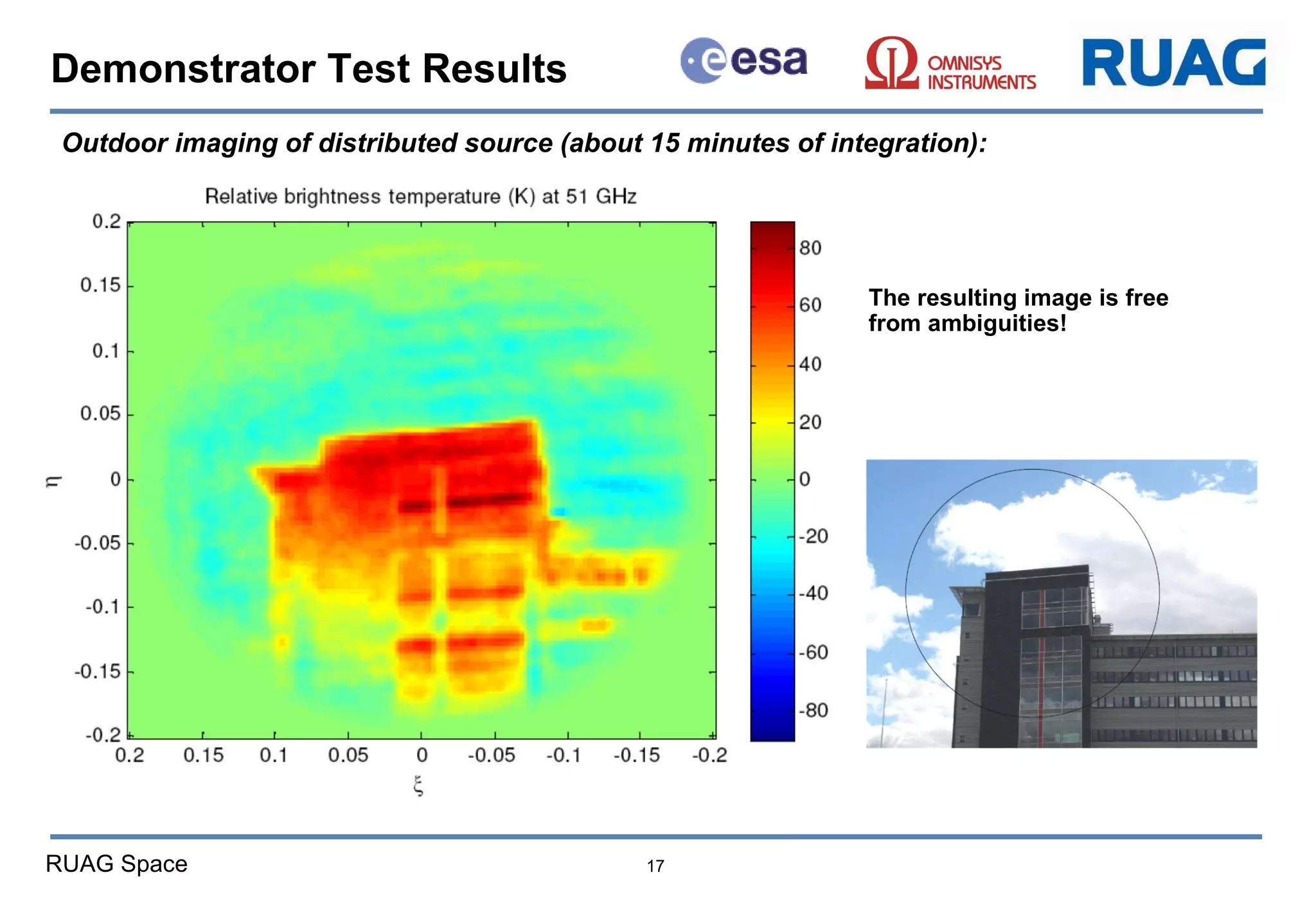
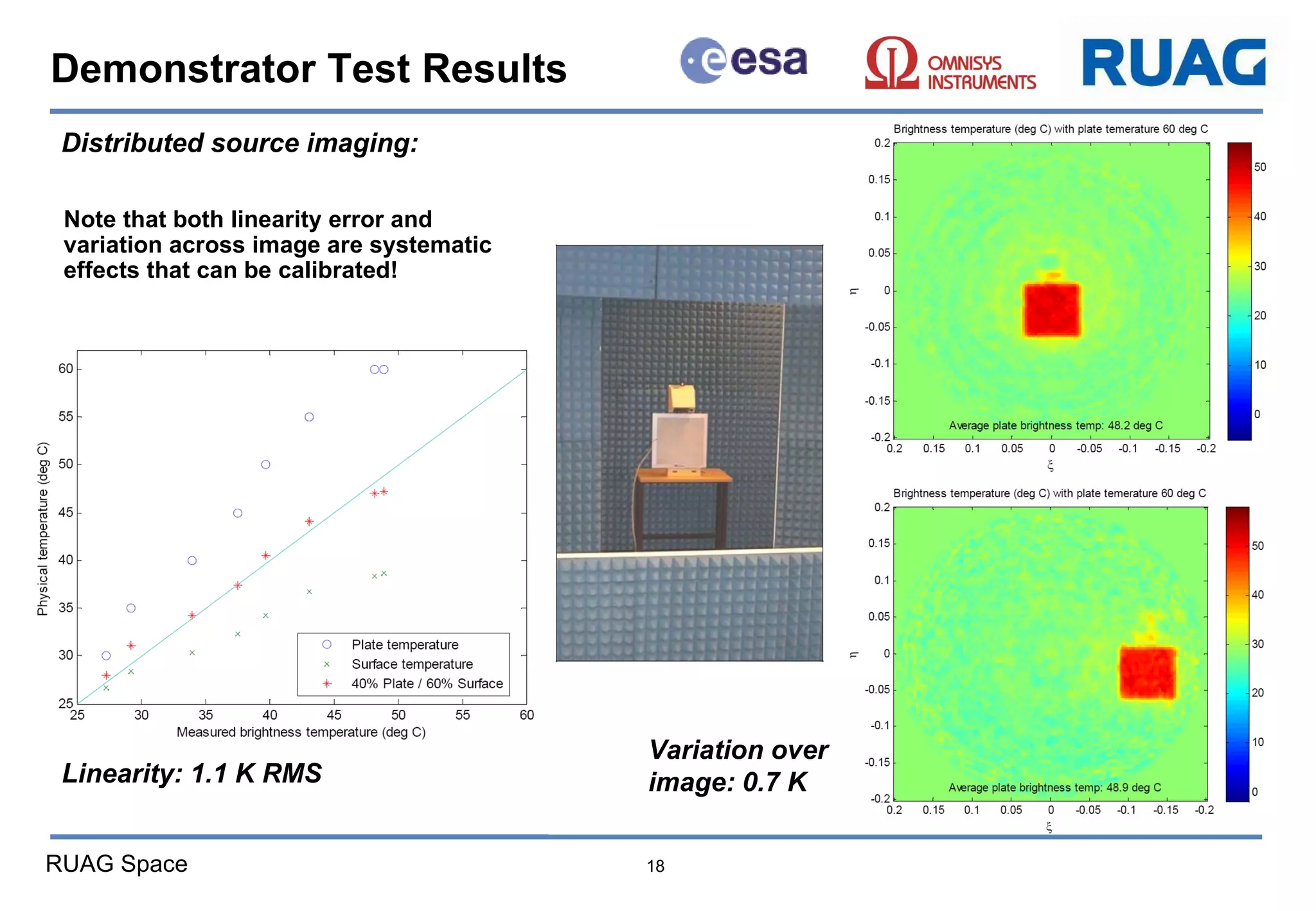
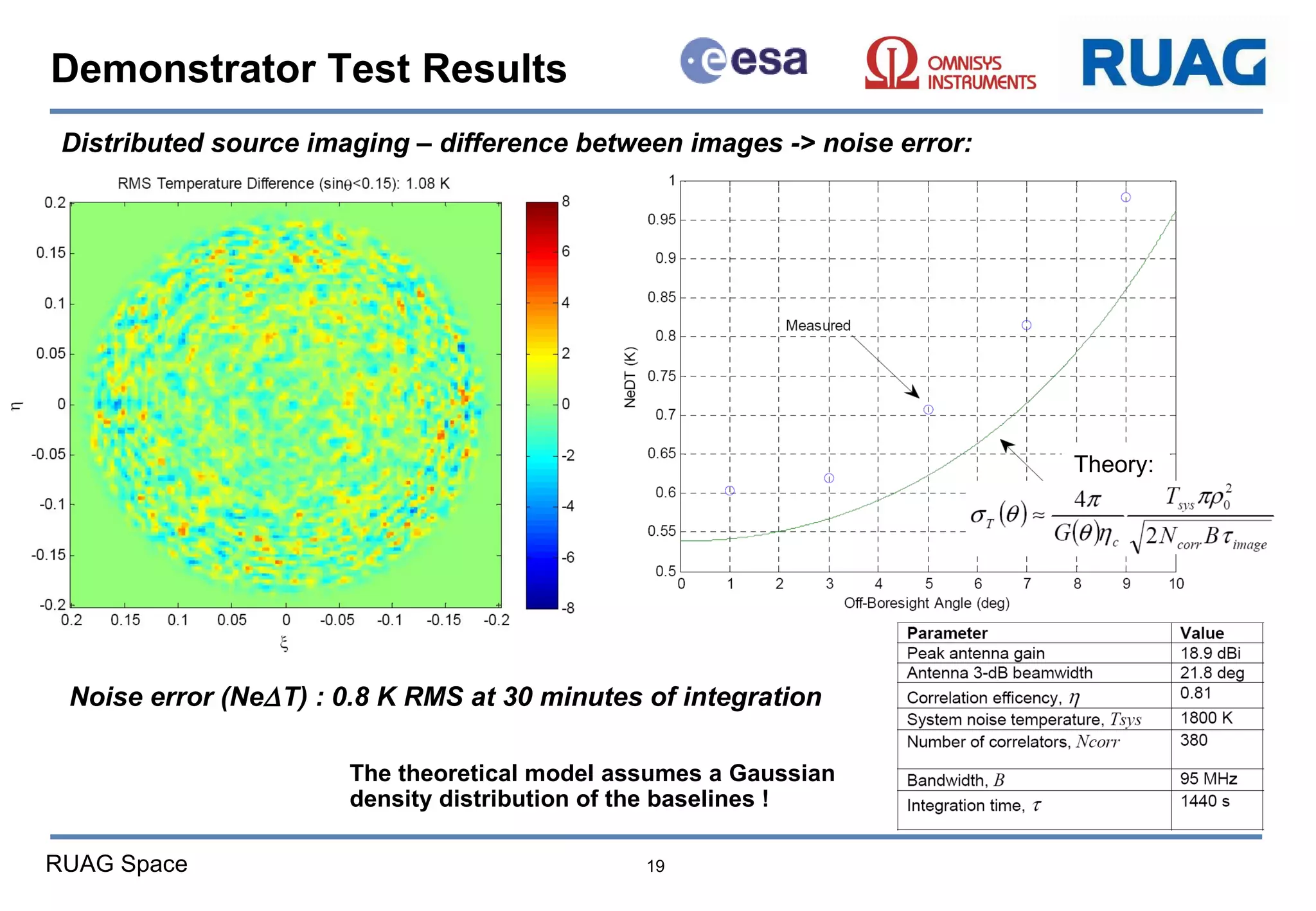
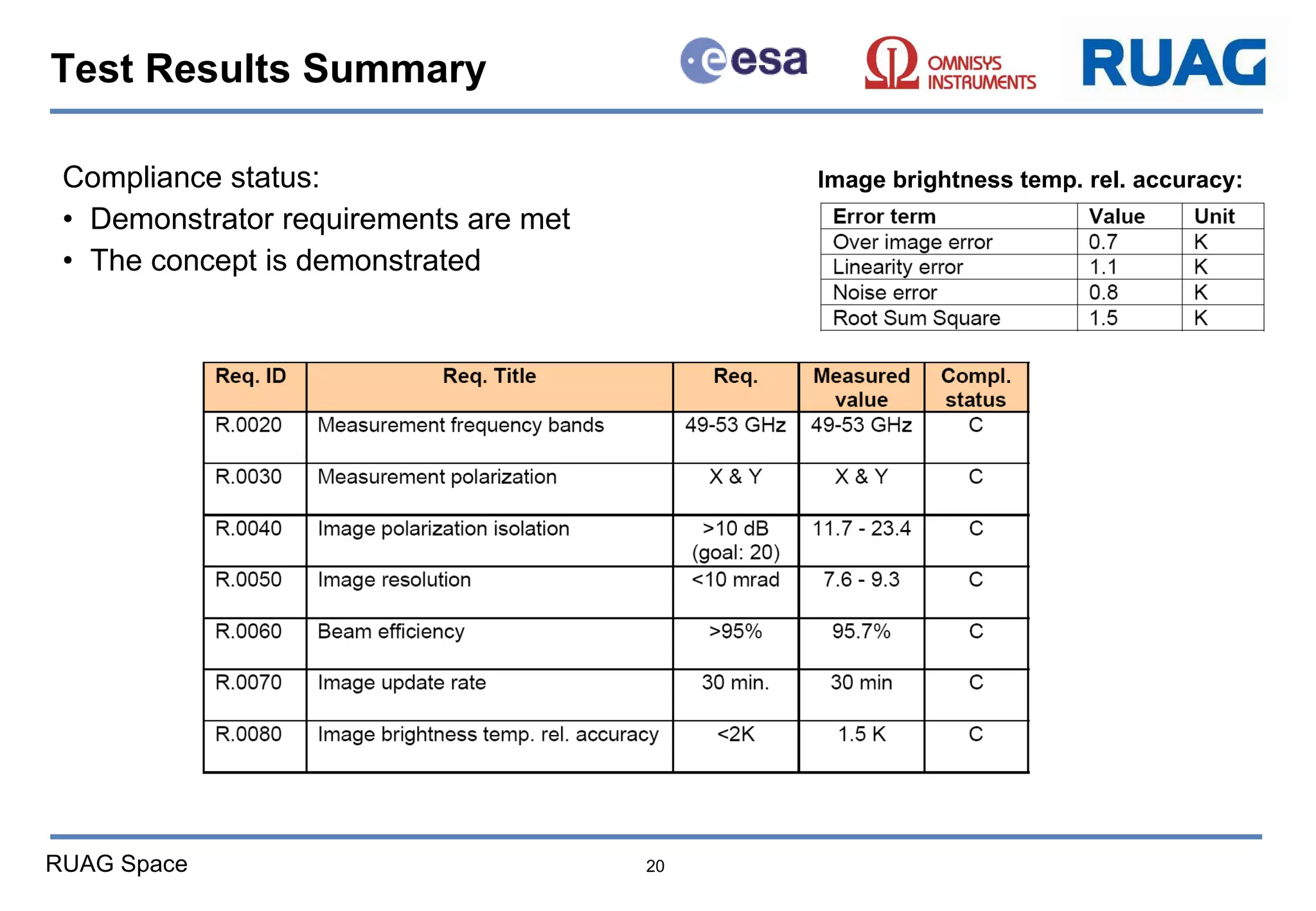
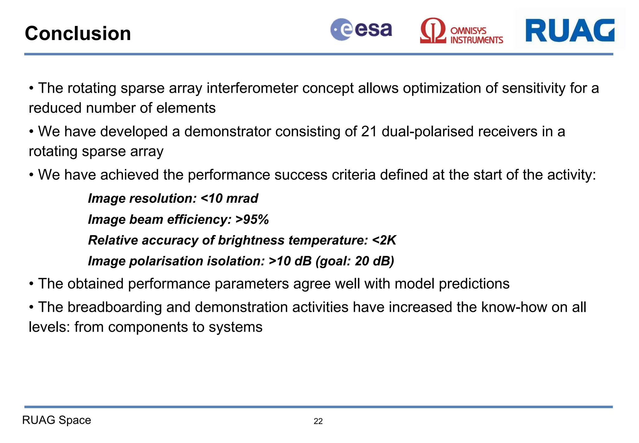
Demonstrator Test Results for  the GEO Atmospheric Sounder (GAS)  Jacob Christensen 1 , Anders Carlström 1 ,  Johan Embretsén 2 ,  Andreas Colliander 3,4 ,  and Peter de Maagt 4   1 RUAG Space AB, Göteborg, Sweden 2 Omnisys Instruments AB, Göteborg, Sweden  3 Jet Propulsion Laboratory, Pasadena, California, USA  4 European Space Agency, Noordwijk, The Netherlands IGARSS 2011 Vancouver  28 July 2011
Project Overview The overall study objective (Phase 1&2) has been to develop an imaging microwave sounder concept for Geostationary Earth Orbit (GEO) Phase 1 was a feasibility study where the concept was developed and analysed Phase 2 has demonstrated the concept by developing and testing a fully operational interferometer system Study Team: European Space Agency (ESA) Specifications and coordination of the project RUAG Space (Göteborg, Sweden) Focusing on: System design Image retrieval processing and calibration Antenna design Mechanical/thermal design Omnisys Instruments   (Göteborg, Sweden) Focusing on: System design Front-End Electronics design Back-End Electronics design The ESA GEO Atmospheric Sounder Technology Project
Background and objectives Meteorological needs for nowcasting & short range forecasting in the 2015 – 2020 time frame 15-30 minute revisit time 30 km resolution 380 GHz Four frequency bands of interest centred around: 53, 118, 183, 380 GHz Temperature (AMSU-A) Most important for NWP ! High altitude  temperature High altitude  humidity Humidity (AMSU-B) 166 346
Driving requirements Requirements 2015 – 2020 15 - 30min Revisit Time => Geostationary Orbit All Weather Capability => Requires the 53 GHz band 30 km Resolution => 8 m Aperture Solution: Foldable Interferometer Can be Launched Can Operate on GEO S/C  Rotating Interferometer Provides images with finer resolution  as compared to a stationary interferometer  ( for a given  number of mm-wave receivers)
Interferometer element layout Minimum spacing of 3.5   to avoid aliasing Redundant baselines improves the instrument calibration Good signal strength for 6, 9 ,12, 16, 19, 22   due to size of Earth disc Large spacing near the centre to enable interlacing several frequency bands u-v sampling after rotation instantaneous u-v sampling  u v x y
Instrument electronics The polarisation vector rotates during measurement All four Stokes parameters are measured Improved sensitivity
Mechanical design Deployment hinge Attachment structure Rotational drive Boom structure Radiator Mounting support 53 GHz 380 GHz 118 GHz 183 GHz
Instrument budgets Four frequency bands with polarimetric capability Power: 406 W  Mass: 375 kg The concept is scalable !
Includes the central part of the instrument:  21 dual-pol interferometer elements (53 GHz band) Objective: to demonstrate the imaging concept with rotation, calibration, and post-processing 53 GHz demonstrator Demonstrator characteristics Parameter Value Remark Frequency band 49-53 GHz Single 90 MHz channel Number of elements 21 Dual polarisation Longest baseline 75 cm ~140   Image Resolution <10 mrad ~300 km on earth Relative accuracy < 2K
Antenna design Coupling between neighbouring elements: < -67 dB
Front-end design LO input Antenna RF inputs (2 pol) IF outputs MMIC designed in collaboration with Chalmers
Demonstrator integration 21 front-ends with antennas Cross-correlator core (42 inputs) Assembled on rotational drive
Demonstrator test campaign Parameters to verify Image angular resolution Image beam efficiency Image polarisation isolation Image relative accuracy Sources Calibration sources:  Hot & Cold Loads Imaging sources:   Noise point source   CW point sources   Distributed source Distributed source Noise CW CW
Demonstrator test results Relative calibration of all elements using point source in boresight: Gain stability over 2 hours: 0.03 dB RMS @ 51 GHz Phase stability over 2 hours: 0.2 deg RMS @ 51 GHz
Demonstrator test results Point source imaging: Demonstrator configuration 1 deg/s Polarization XX-pol YY-pol Measured pol. isolation is dominated by co-polar sidelobes ! PS1  PS2
Demonstrator test results Solar imaging – complete transition (boresight elevation is 47.4 deg): 11:30 12:30 12:00
Outdoor imaging of distributed source (about 15 minutes of integration): Demonstrator Test Results The resulting image is free from ambiguities!
Demonstrator Test Results Distributed source imaging: Linearity: 1.1 K RMS Variation over image: 0.7 K Note that both linearity error and variation across image are systematic effects that can be calibrated!
Distributed source imaging – difference between images -> noise error: Demonstrator Test Results Noise error (Ne  T) : 0.8 K RMS at 30 minutes of integration The theoretical model assumes a Gaussian density distribution of the baselines ! Theory:
Compliance status: Demonstrator requirements are met The concept is demonstrated Test Results Summary Image brightness temp. rel. accuracy:
Related activities Deployment test Parallel study: Ultra-stable structure for interferometric instrument Parallel study: MMIC for 118 and 183 GHz  Results show that the design is viable 90 & 118 GHz 166 & 183 GHz NF = 3.1 dB NF = 6.0 dB Packaging Expected with 50 nm mHEMT (flight design): NF = 2.5 dB NF = 4.8 dB Receivers produced using 100 nm mHEMT:
Conclusion The rotating sparse array interferometer concept allows optimization of sensitivity for a reduced number of elements We have developed a demonstrator consisting of 21 dual-polarised receivers in a rotating sparse array  •  We have achieved the performance success criteria defined at the start of the activity: Image resolution: <10 mrad Image beam efficiency: >95% Relative accuracy of brightness temperature: <2K Image polarisation isolation: >10 dB (goal: 20 dB) •  The obtained performance parameters agree well with model predictions The breadboarding and demonstration activities have increased the know-how on all levels: from components to systems

GAS@IGARSS2011.ppt

  • 1.
    Demonstrator Test Resultsfor the GEO Atmospheric Sounder (GAS) Jacob Christensen 1 , Anders Carlström 1 , Johan Embretsén 2 , Andreas Colliander 3,4 , and Peter de Maagt 4 1 RUAG Space AB, Göteborg, Sweden 2 Omnisys Instruments AB, Göteborg, Sweden 3 Jet Propulsion Laboratory, Pasadena, California, USA 4 European Space Agency, Noordwijk, The Netherlands IGARSS 2011 Vancouver 28 July 2011
  • 2.
    Project Overview Theoverall study objective (Phase 1&2) has been to develop an imaging microwave sounder concept for Geostationary Earth Orbit (GEO) Phase 1 was a feasibility study where the concept was developed and analysed Phase 2 has demonstrated the concept by developing and testing a fully operational interferometer system Study Team: European Space Agency (ESA) Specifications and coordination of the project RUAG Space (Göteborg, Sweden) Focusing on: System design Image retrieval processing and calibration Antenna design Mechanical/thermal design Omnisys Instruments (Göteborg, Sweden) Focusing on: System design Front-End Electronics design Back-End Electronics design The ESA GEO Atmospheric Sounder Technology Project
  • 3.
    Background and objectivesMeteorological needs for nowcasting & short range forecasting in the 2015 – 2020 time frame 15-30 minute revisit time 30 km resolution 380 GHz Four frequency bands of interest centred around: 53, 118, 183, 380 GHz Temperature (AMSU-A) Most important for NWP ! High altitude temperature High altitude humidity Humidity (AMSU-B) 166 346
  • 4.
    Driving requirements Requirements2015 – 2020 15 - 30min Revisit Time => Geostationary Orbit All Weather Capability => Requires the 53 GHz band 30 km Resolution => 8 m Aperture Solution: Foldable Interferometer Can be Launched Can Operate on GEO S/C Rotating Interferometer Provides images with finer resolution as compared to a stationary interferometer ( for a given number of mm-wave receivers)
  • 5.
    Interferometer element layoutMinimum spacing of 3.5  to avoid aliasing Redundant baselines improves the instrument calibration Good signal strength for 6, 9 ,12, 16, 19, 22  due to size of Earth disc Large spacing near the centre to enable interlacing several frequency bands u-v sampling after rotation instantaneous u-v sampling u v x y
  • 6.
    Instrument electronics Thepolarisation vector rotates during measurement All four Stokes parameters are measured Improved sensitivity
  • 7.
    Mechanical design Deploymenthinge Attachment structure Rotational drive Boom structure Radiator Mounting support 53 GHz 380 GHz 118 GHz 183 GHz
  • 8.
    Instrument budgets Fourfrequency bands with polarimetric capability Power: 406 W Mass: 375 kg The concept is scalable !
  • 9.
    Includes the centralpart of the instrument: 21 dual-pol interferometer elements (53 GHz band) Objective: to demonstrate the imaging concept with rotation, calibration, and post-processing 53 GHz demonstrator Demonstrator characteristics Parameter Value Remark Frequency band 49-53 GHz Single 90 MHz channel Number of elements 21 Dual polarisation Longest baseline 75 cm ~140  Image Resolution <10 mrad ~300 km on earth Relative accuracy < 2K
  • 10.
    Antenna design Couplingbetween neighbouring elements: < -67 dB
  • 11.
    Front-end design LOinput Antenna RF inputs (2 pol) IF outputs MMIC designed in collaboration with Chalmers
  • 12.
    Demonstrator integration 21front-ends with antennas Cross-correlator core (42 inputs) Assembled on rotational drive
  • 13.
    Demonstrator test campaignParameters to verify Image angular resolution Image beam efficiency Image polarisation isolation Image relative accuracy Sources Calibration sources: Hot & Cold Loads Imaging sources: Noise point source CW point sources Distributed source Distributed source Noise CW CW
  • 14.
    Demonstrator test resultsRelative calibration of all elements using point source in boresight: Gain stability over 2 hours: 0.03 dB RMS @ 51 GHz Phase stability over 2 hours: 0.2 deg RMS @ 51 GHz
  • 15.
    Demonstrator test resultsPoint source imaging: Demonstrator configuration 1 deg/s Polarization XX-pol YY-pol Measured pol. isolation is dominated by co-polar sidelobes ! PS1 PS2
  • 16.
    Demonstrator test resultsSolar imaging – complete transition (boresight elevation is 47.4 deg): 11:30 12:30 12:00
  • 17.
    Outdoor imaging ofdistributed source (about 15 minutes of integration): Demonstrator Test Results The resulting image is free from ambiguities!
  • 18.
    Demonstrator Test ResultsDistributed source imaging: Linearity: 1.1 K RMS Variation over image: 0.7 K Note that both linearity error and variation across image are systematic effects that can be calibrated!
  • 19.
    Distributed source imaging– difference between images -> noise error: Demonstrator Test Results Noise error (Ne  T) : 0.8 K RMS at 30 minutes of integration The theoretical model assumes a Gaussian density distribution of the baselines ! Theory:
  • 20.
    Compliance status: Demonstratorrequirements are met The concept is demonstrated Test Results Summary Image brightness temp. rel. accuracy:
  • 21.
    Related activities Deploymenttest Parallel study: Ultra-stable structure for interferometric instrument Parallel study: MMIC for 118 and 183 GHz Results show that the design is viable 90 & 118 GHz 166 & 183 GHz NF = 3.1 dB NF = 6.0 dB Packaging Expected with 50 nm mHEMT (flight design): NF = 2.5 dB NF = 4.8 dB Receivers produced using 100 nm mHEMT:
  • 22.
    Conclusion The rotatingsparse array interferometer concept allows optimization of sensitivity for a reduced number of elements We have developed a demonstrator consisting of 21 dual-polarised receivers in a rotating sparse array • We have achieved the performance success criteria defined at the start of the activity: Image resolution: <10 mrad Image beam efficiency: >95% Relative accuracy of brightness temperature: <2K Image polarisation isolation: >10 dB (goal: 20 dB) • The obtained performance parameters agree well with model predictions The breadboarding and demonstration activities have increased the know-how on all levels: from components to systems