Downloaded 437 times
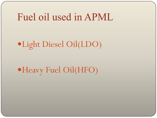
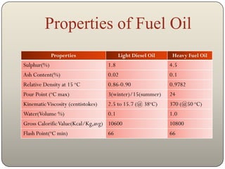
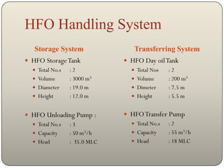
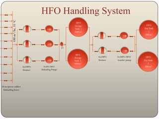
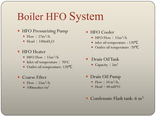

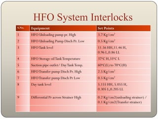

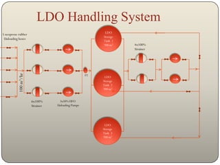
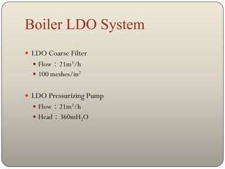
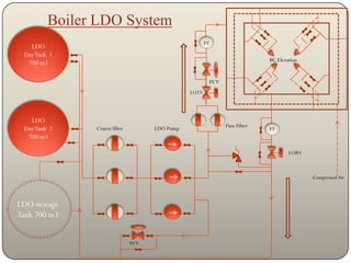
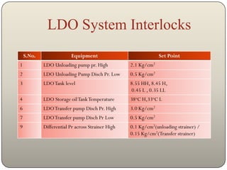
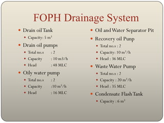
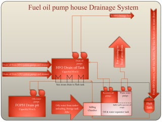
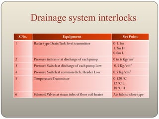

The document summarizes the fuel oil and drainage systems at APML. It describes the two types of fuel oil used - light diesel oil (LDO) and heavy fuel oil (HFO) - and provides details on their properties, storage, transfer, and boiler systems. It also outlines the drainage system for collecting and separating oil and water from the fuel systems.