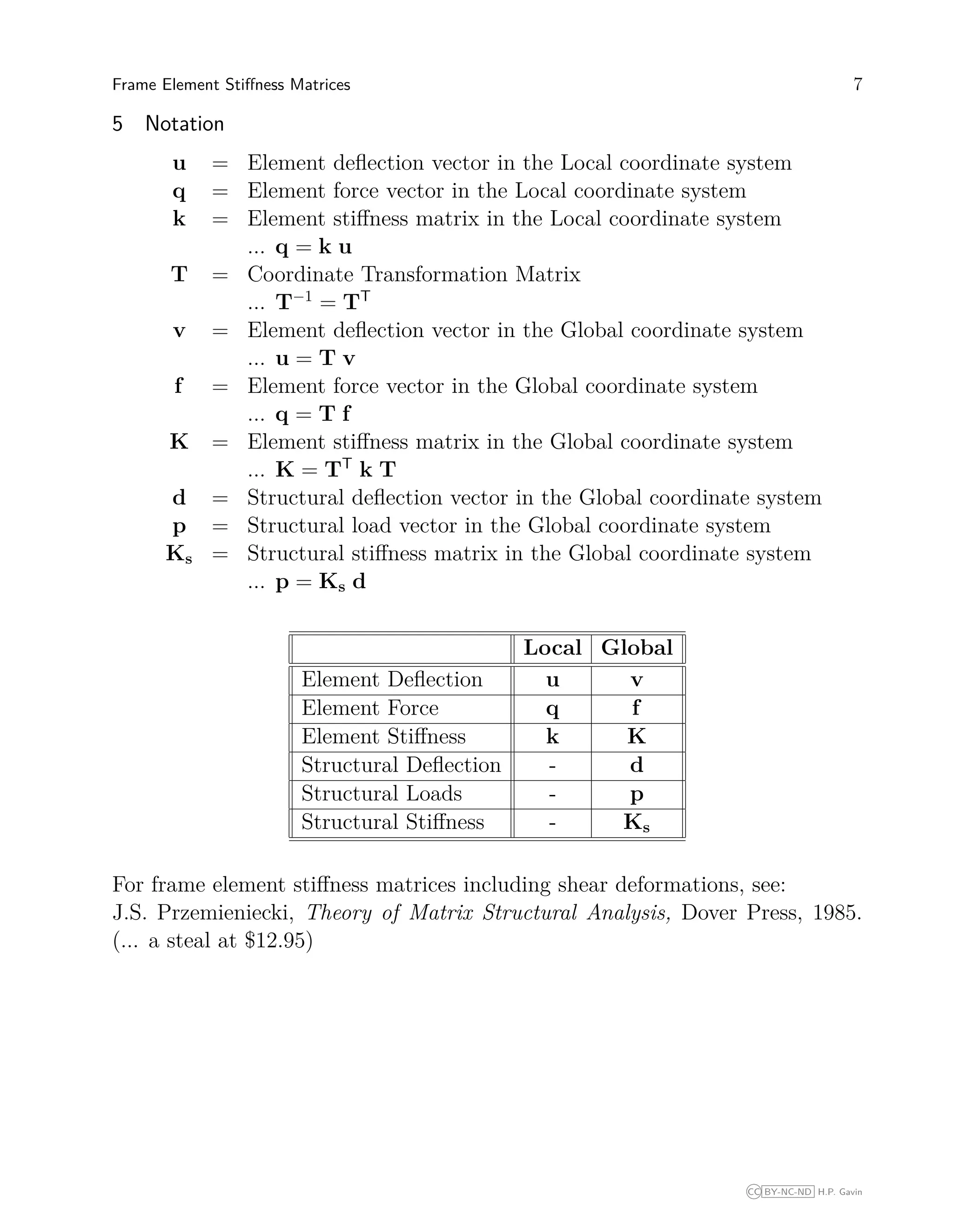
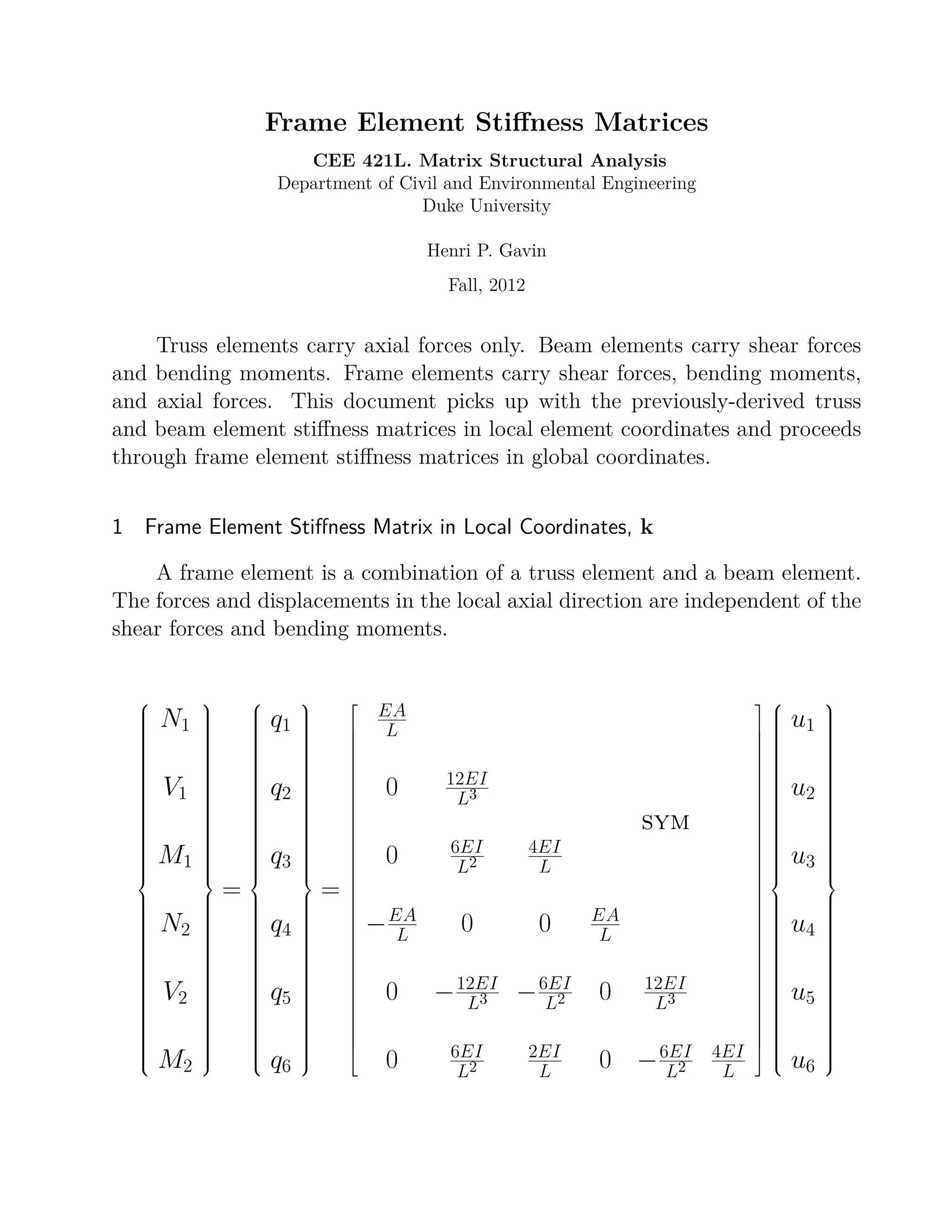
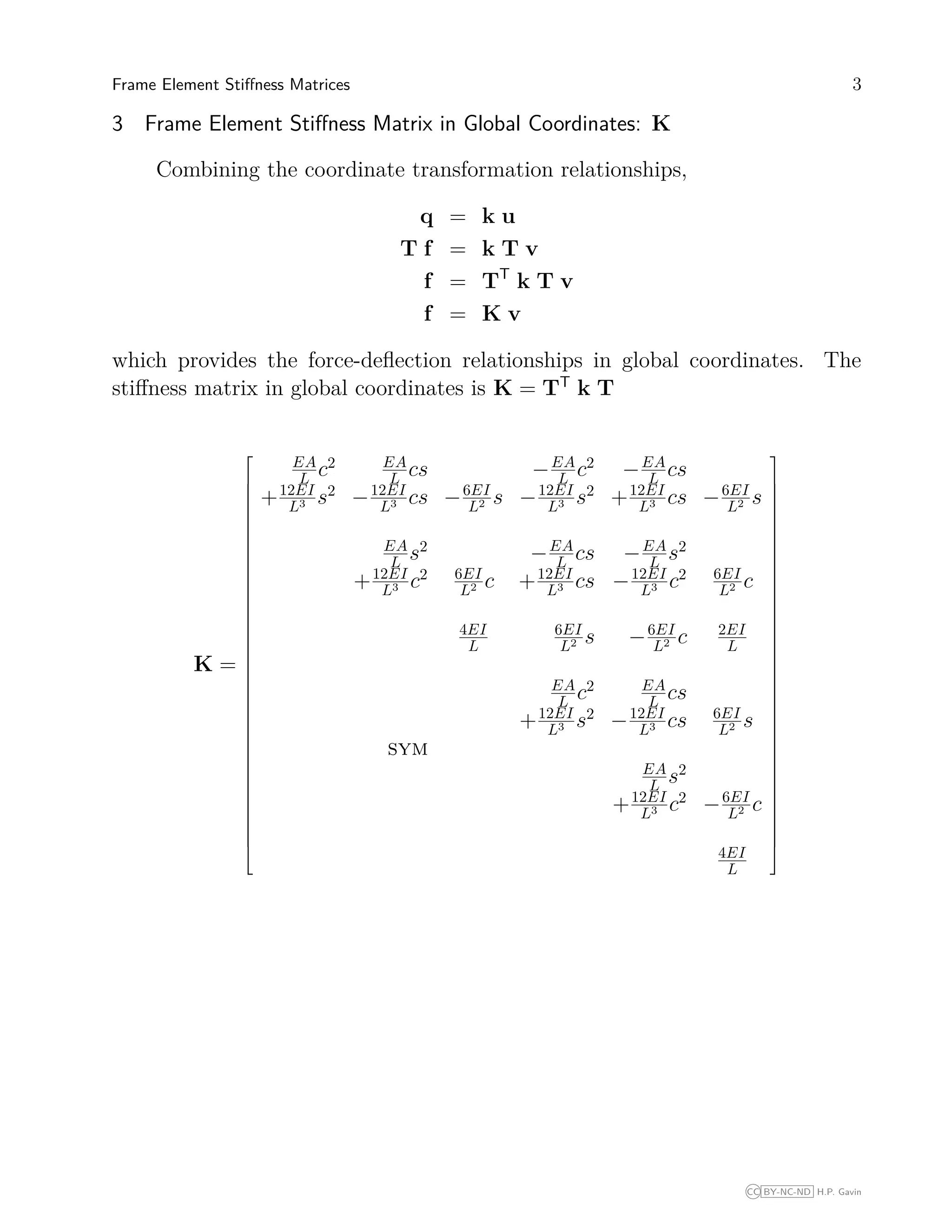
This document discusses frame element stiffness matrices. It explains that frame elements carry axial forces, bending moments, and shear forces. It presents the frame element stiffness matrix in local coordinates and shows how to transform it to global coordinates using a coordinate transformation matrix. It also describes how to modify the stiffness matrix to account for frame elements with end releases, such as pinned-fixed or fixed-pinned elements, by partitioning the matrix and setting rows and columns associated with released degrees of freedom to zero.
![4 CEE 421L. Matrix Structural Analysis – Duke University – Fall 2012 – H.P. Gavin
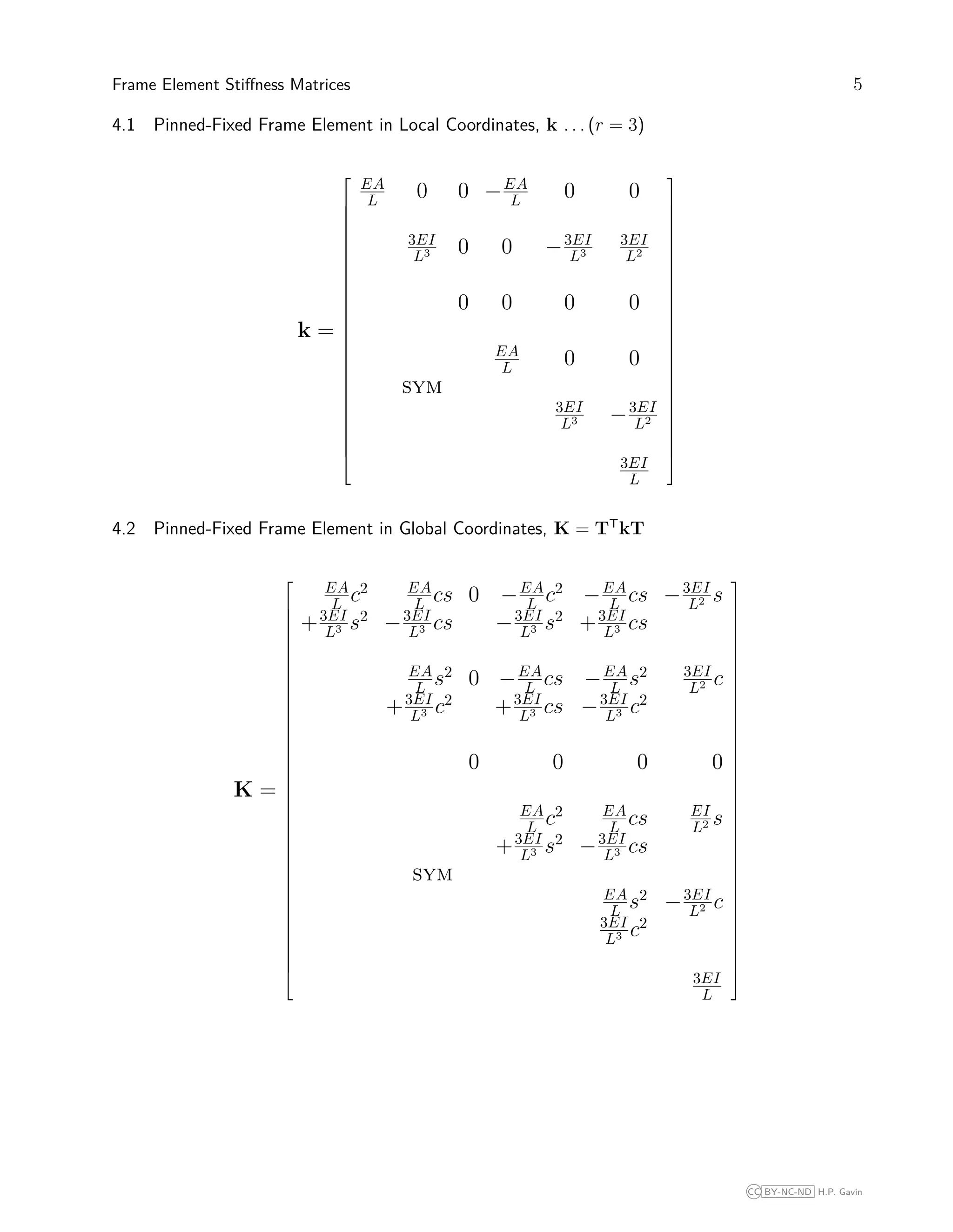
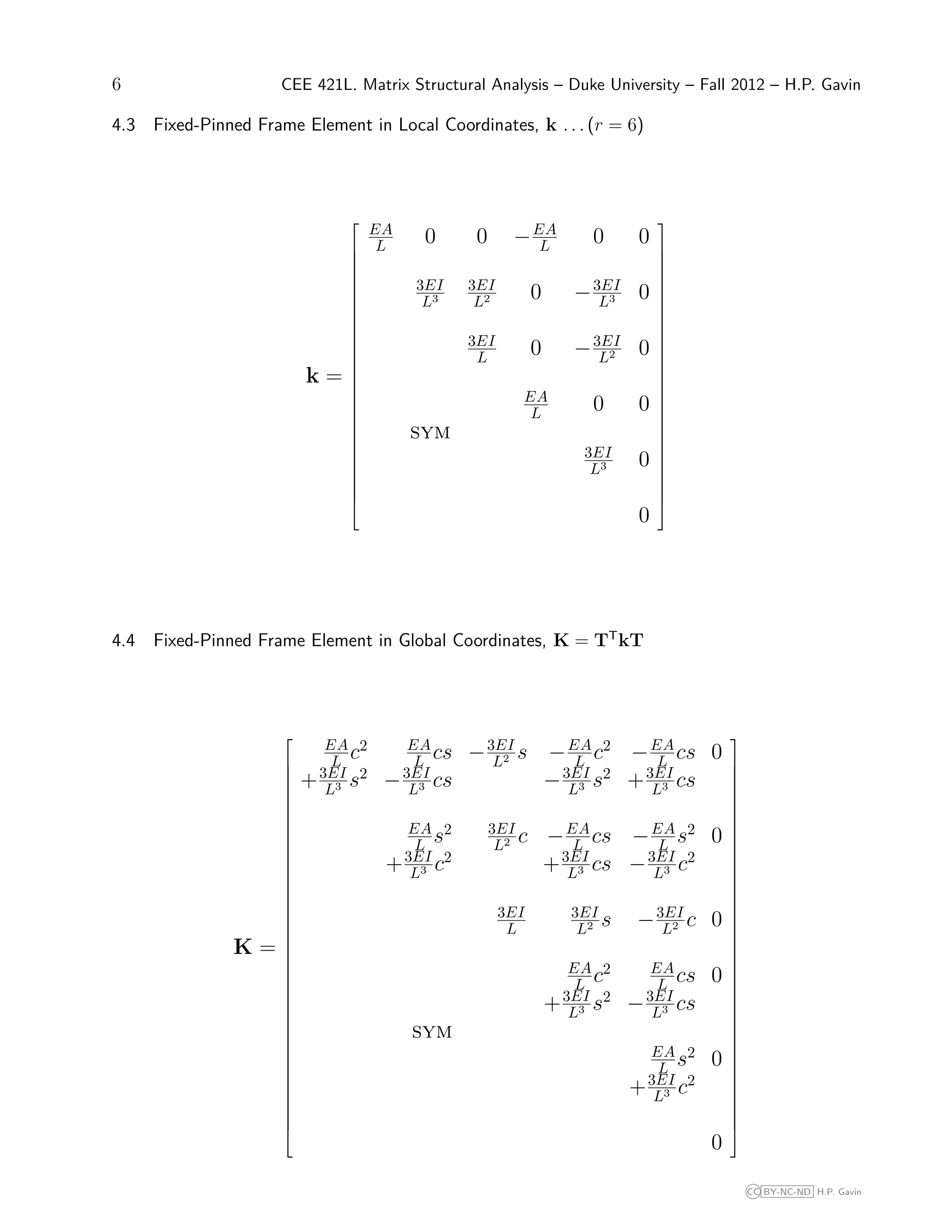
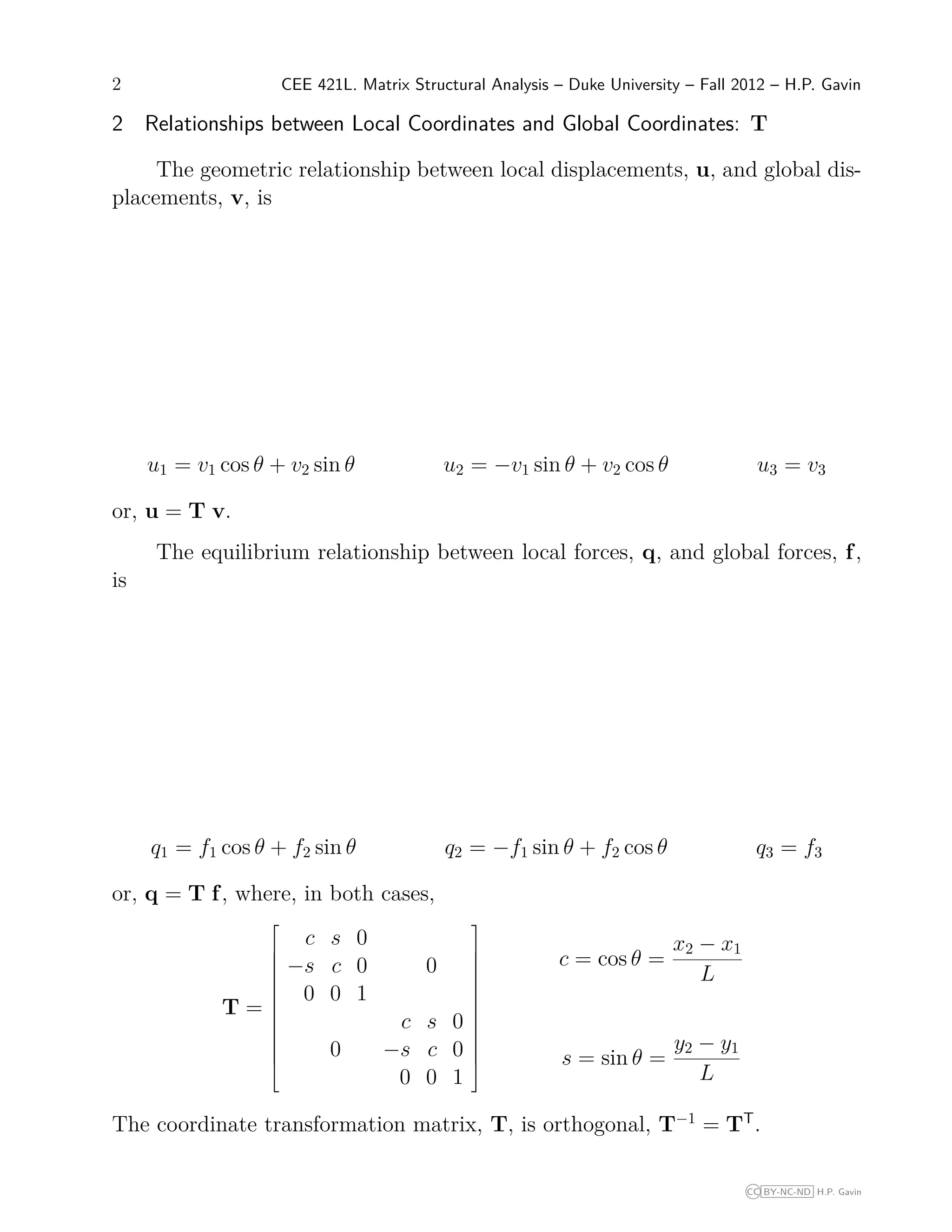
4 Frame Element Stiffness Matrices for Elements with End-Releases
Some elements in a frame may not be fixed at both ends. For example,
an element may be fixed at one end and pinned at the other. Or, the element
may be guided on one end so that the element shear forces at that end are zero.
Or, the frame element may be pinned at both ends, so that it acts like a truss
element. Such modifications to the frame element naturally affect the elements
stiffness matrix.
Consider a frame element in which a set of end-coordinates r are released,
and the goal is to find a stiffness matrix relation for the primary p retained
coordinates. The element end forces at the released coordinates, qr are all zero.
One can partition the element stiffness matrix equation as follows
qp
qr
kpp kpr
krp krr
up
ur
The element displacement coordinates at the released coordinates do not equal
the structural displacements at the collocated structural coordinates, since the
coordinates r are released. Since the element end forces at the released coor-
dinates are all zero (qr = 0), the element end displacements at the released
coordinates must be related to the displacements at the primary (retained)
coordinates as:
ur = −k−1
rr krpup
The element stiffness matrix equation relating qp and up is
qp = kpp − kprk−1
rr krp up
The rows and columns of the released element stiffness matrix corresponding
to the released coordinates, r, are set to zero. The rows and columns of the
released element stiffness matrix corresponding to the retained coordinates, p,
are [kpp − kprk−1
rr krp]. This is the element stiffness matrix that should assemble
into the structural coordinates collocated with the primary (retained) coordi-
nates p. The following sections give examples for pinned-fixed and fixed-pinned
frame elements. Element stiffness matrices for many other end-release cases
can be easily computed.
CC BY-NC-ND H.P. Gavin](https://image.slidesharecdn.com/frame-element-200626150933/75/Frame-element-4-2048.jpg)