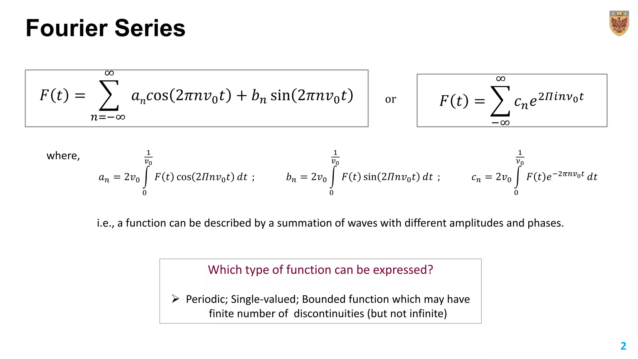
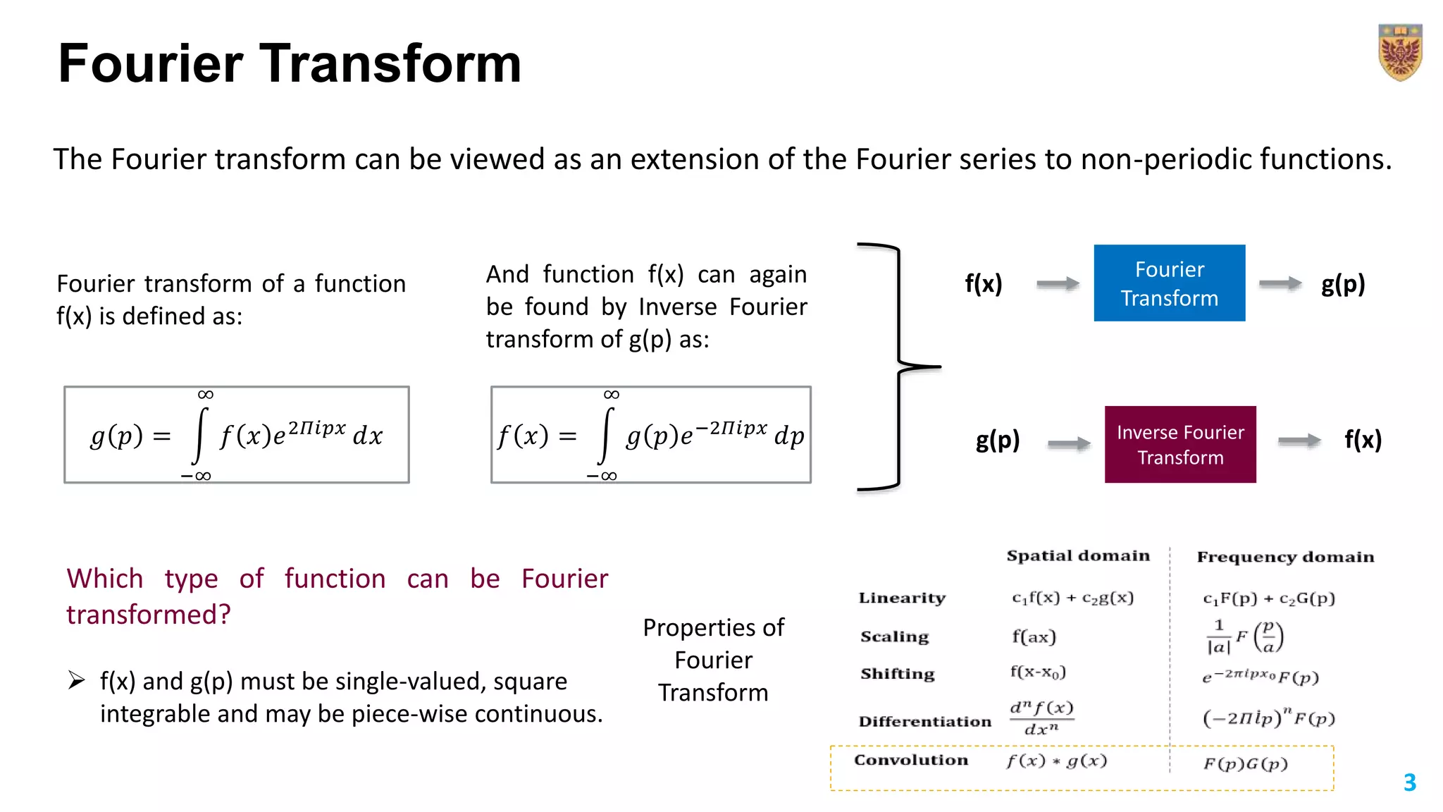
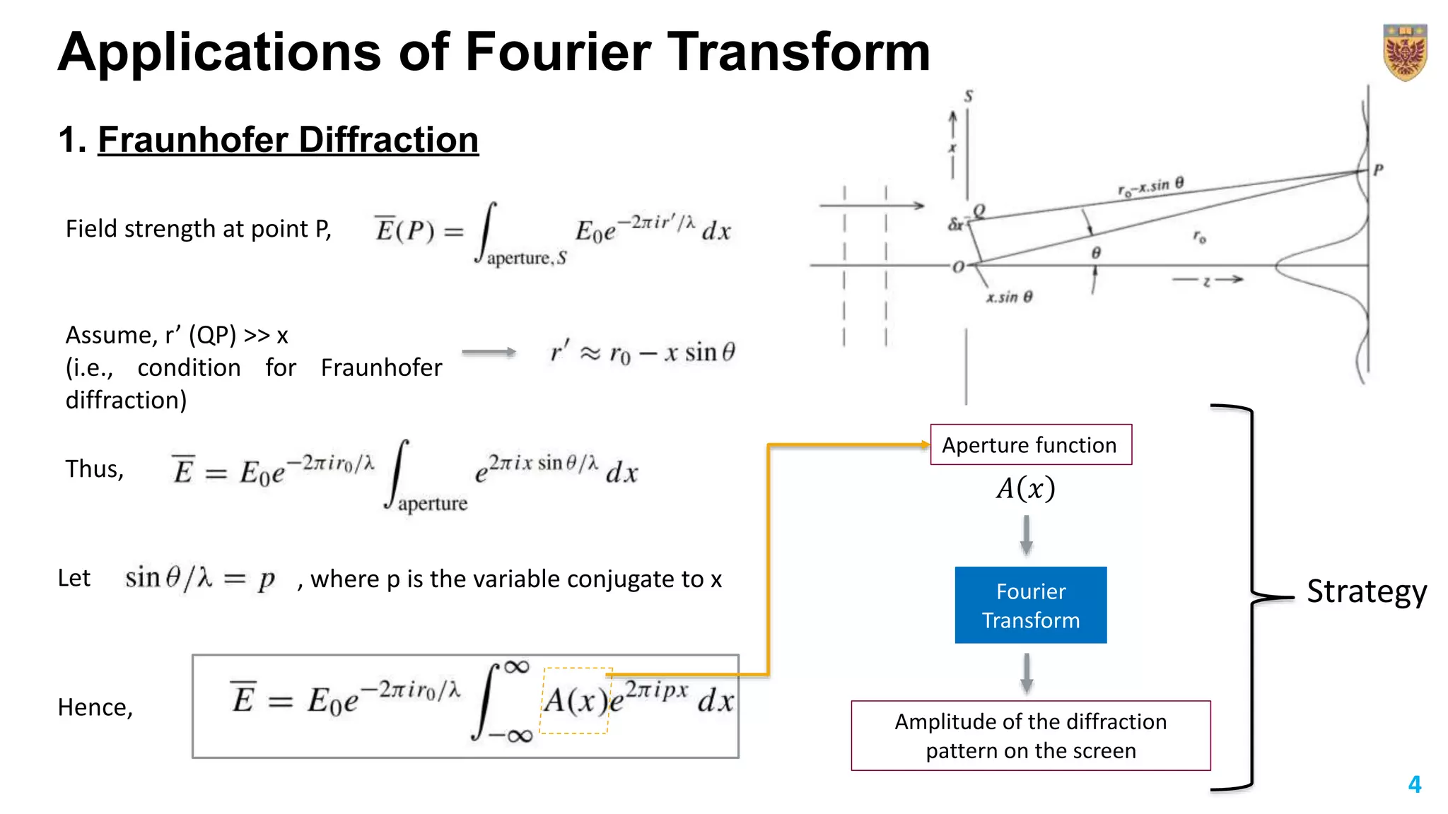
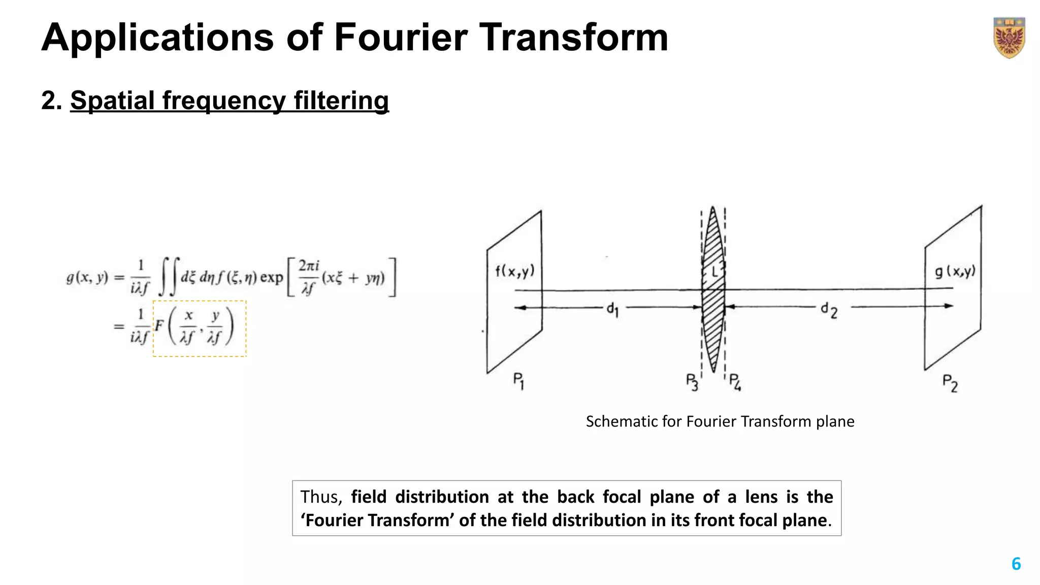
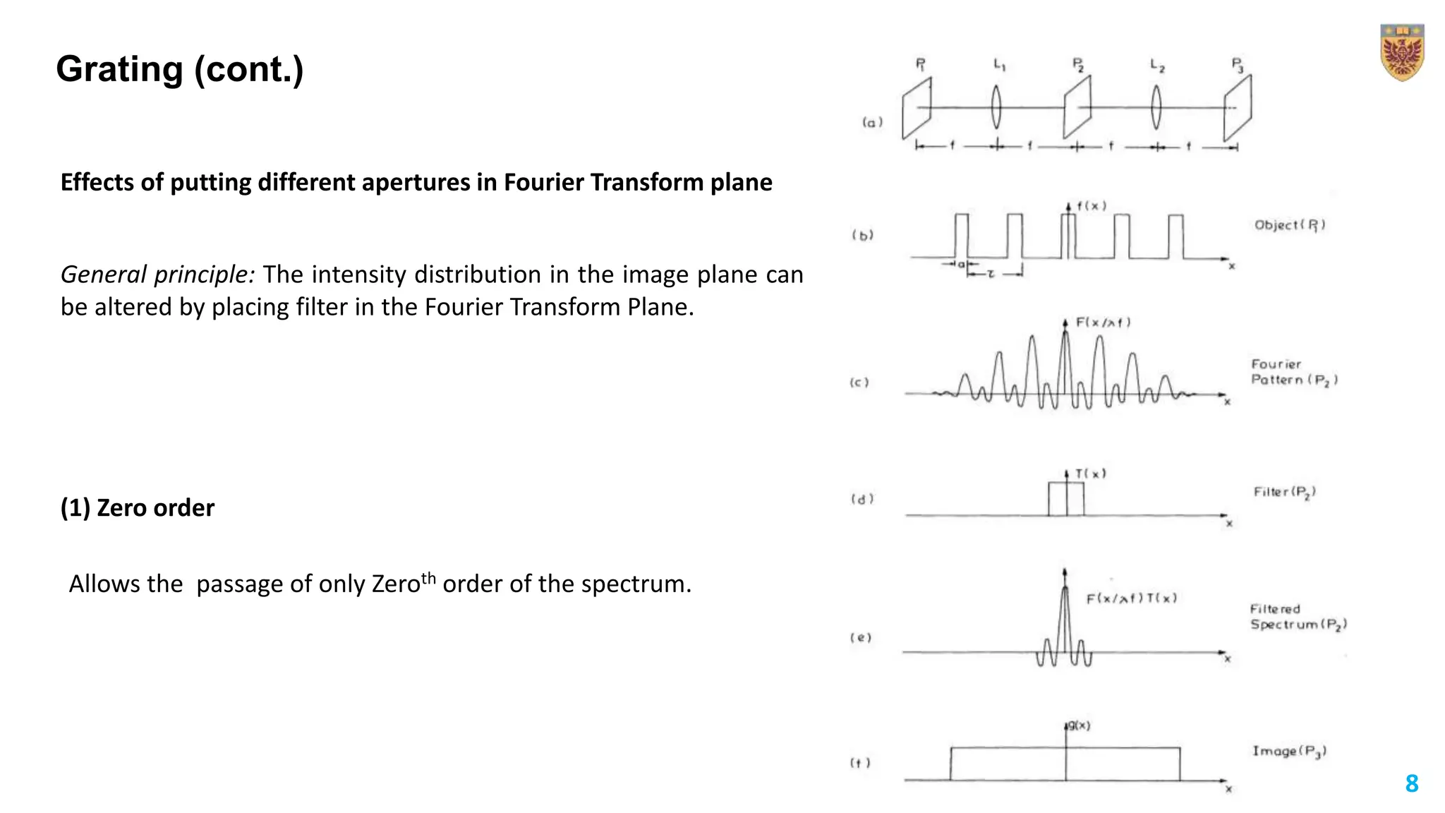
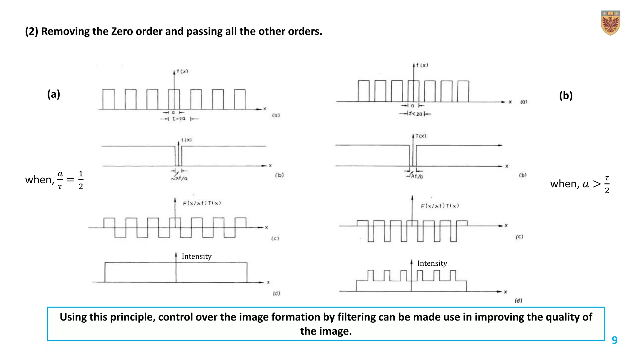
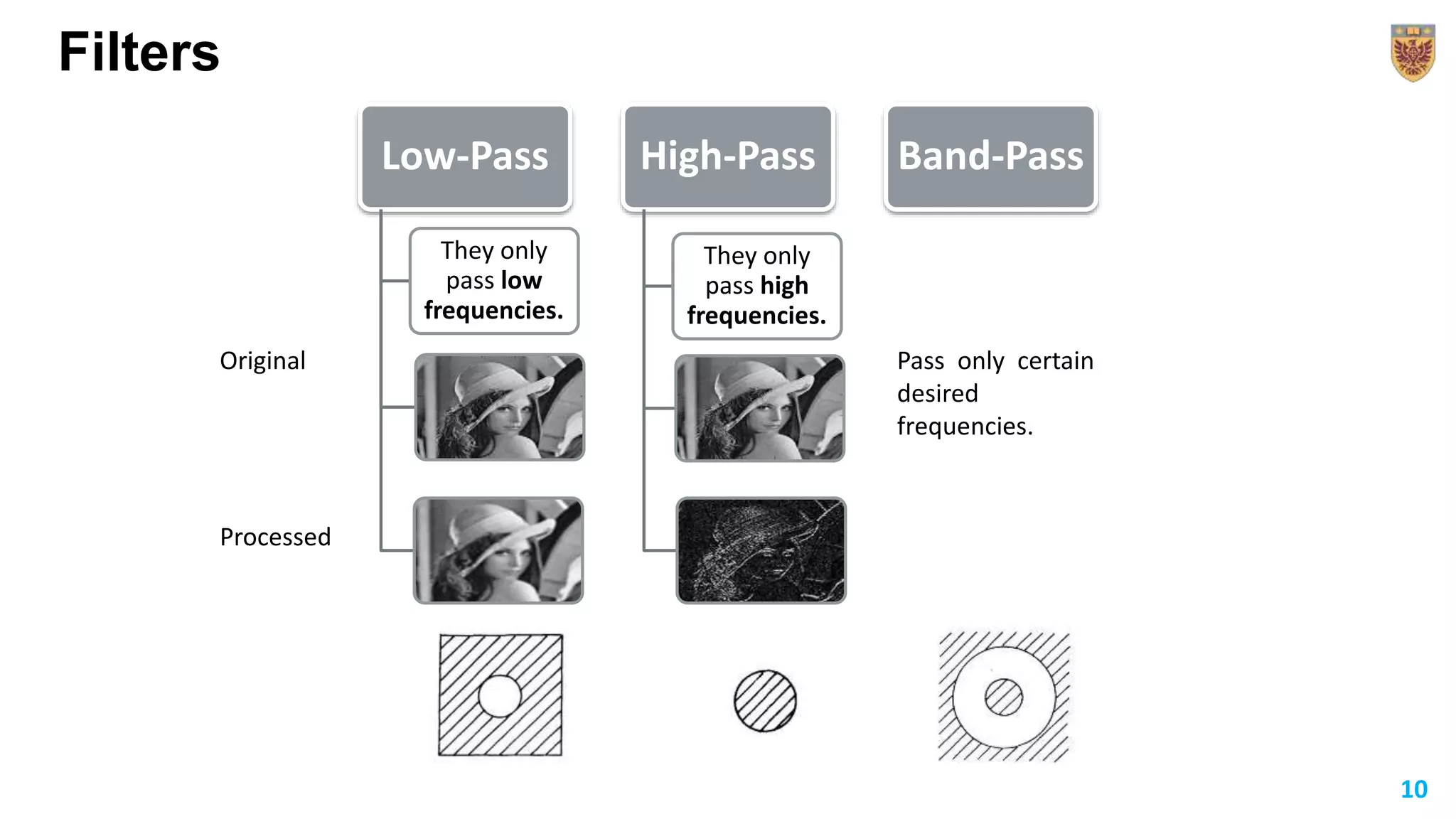
12/17/2019 1
Applications of Fourier Transform
1
Krishna Jangid
PhD Student
Department of Engineering Physics
Fourier Series
𝐹 𝑡 =
𝑛=−∞
∞
𝑎 𝑛 𝑐os 2𝜋𝑛𝑣0 𝑡 + 𝑏 𝑛 sin 2𝜋𝑛𝑣0 𝑡
𝑎 𝑛 = 2𝑣0
0
1
𝑣0
𝐹 𝑡 cos 2𝛱𝑛𝑣0 𝑡 ⅆ𝑡 ; 𝑏 𝑛 = 2𝑣0
0
1
𝑣0
𝐹 𝑡 sin 2𝛱𝑛𝑣0 𝑡 ⅆ𝑡 ;
𝐹 𝑡 =
−∞
∞
𝑐 𝑛ⅇ2𝛱ⅈ𝑛𝜈0 𝑡
𝑐 𝑛 = 2𝑣0
0
1
𝜈0
𝐹 𝑡 ⅇ−2𝜋𝑛𝑣0 𝑡
ⅆ𝑡
or
where,
Which type of function can be expressed?
 Periodic; Single-valued; Bounded function which may have
finite number of discontinuities (but not infinite)
i.e., a function can be described by a summation of waves with different amplitudes and phases.
2
Fourier Transform
The Fourier transform can be viewed as an extension of the Fourier series to non-periodic functions.
𝑔 𝑝 =
−∞
∞
𝑓 𝑥 ⅇ2𝛱ⅈ𝑝𝑥
ⅆ𝑥
Fourier transform of a function
f(x) is defined as:
And function f(x) can again
be found by Inverse Fourier
transform of g(p) as:
𝑓 𝑥 =
−∞
∞
𝑔 𝑝 ⅇ−2𝛱ⅈ𝑝𝑥
ⅆ𝑝
f(x)
Fourier
Transform
g(p)
g(p) Inverse Fourier
Transform
f(x)
Which type of function can be Fourier
transformed?
 f(x) and g(p) must be single-valued, square
integrable and may be piece-wise continuous.
Properties of
Fourier
Transform
3
Applications of Fourier Transform
1. Fraunhofer Diffraction
Field strength at point P,
Assume, r’ (QP) >> x
(i.e., condition for Fraunhofer
diffraction)
Thus,
Let , where p is the variable conjugate to x
Hence,
𝐴 𝑥
Fourier
Transform
Aperture function
Amplitude of the diffraction
pattern on the screen
Strategy
4
Different apertures
1. Single slit (slit width of ‘a’)
2. Double slit (slits of width ‘a’ and spaced ‘b’ apart)
𝐴 𝑥
Aperture function Intensity distribution
𝐸 = 𝑘 𝑠𝑖𝑛 𝑐 𝛱𝑎𝑝 = 𝑘 𝑠𝑖𝑛 𝑐 𝛱 asin 𝜃 𝜆
𝐼 𝜃 = 𝐸𝐸∗ = 𝑘2
𝑠𝑖𝑛 𝑐2
𝛱 asin 𝜃 𝜆
𝐴 𝑥
𝑎
− 𝑏 2 𝑏 2
5
2. Spatial frequency filtering
Applications of Fourier Transform
Thus, field distribution at the back focal plane of a lens is the
‘Fourier Transform’ of the field distribution in its front focal plane.
6
Schematic for Fourier Transform plane
Grating (N slits of width a and separated by 𝜏 distance)
7
Hence, original field distribution is reproduced in the back focal plane of the second lens.
𝐴 𝑥
Aperture function for N-slit grating
Schematic for Fourier Transform plane
General principle: The intensity distribution in the image plane can
be altered by placing filter in the Fourier Transform Plane.
Grating (cont.)
Effects of putting different apertures in Fourier Transform plane
(1) Zero order
Allows the passage of only Zeroth order of the spectrum.
8
(2) Removing the Zero order and passing all the other orders.
when,
𝑎
𝜏
=
1
2 when, 𝑎 >
𝜏
2
Intensity
Intensity
Using this principle, control over the image formation by filtering can be made use in improving the quality of
the image.
9
(a) (b)
Filters
Low-Pass
They only
pass low
frequencies.
High-Pass
They only
pass high
frequencies.
Band-Pass
Original
Processed
Pass only certain
desired
frequencies.
10
Thank you!
11

Fourier series and applications of fourier transform

  • 1.
    12/17/2019 1 Applications ofFourier Transform 1 Krishna Jangid PhD Student Department of Engineering Physics
  • 2.
    Fourier Series 𝐹 𝑡= 𝑛=−∞ ∞ 𝑎 𝑛 𝑐os 2𝜋𝑛𝑣0 𝑡 + 𝑏 𝑛 sin 2𝜋𝑛𝑣0 𝑡 𝑎 𝑛 = 2𝑣0 0 1 𝑣0 𝐹 𝑡 cos 2𝛱𝑛𝑣0 𝑡 ⅆ𝑡 ; 𝑏 𝑛 = 2𝑣0 0 1 𝑣0 𝐹 𝑡 sin 2𝛱𝑛𝑣0 𝑡 ⅆ𝑡 ; 𝐹 𝑡 = −∞ ∞ 𝑐 𝑛ⅇ2𝛱ⅈ𝑛𝜈0 𝑡 𝑐 𝑛 = 2𝑣0 0 1 𝜈0 𝐹 𝑡 ⅇ−2𝜋𝑛𝑣0 𝑡 ⅆ𝑡 or where, Which type of function can be expressed?  Periodic; Single-valued; Bounded function which may have finite number of discontinuities (but not infinite) i.e., a function can be described by a summation of waves with different amplitudes and phases. 2
  • 3.
    Fourier Transform The Fouriertransform can be viewed as an extension of the Fourier series to non-periodic functions. 𝑔 𝑝 = −∞ ∞ 𝑓 𝑥 ⅇ2𝛱ⅈ𝑝𝑥 ⅆ𝑥 Fourier transform of a function f(x) is defined as: And function f(x) can again be found by Inverse Fourier transform of g(p) as: 𝑓 𝑥 = −∞ ∞ 𝑔 𝑝 ⅇ−2𝛱ⅈ𝑝𝑥 ⅆ𝑝 f(x) Fourier Transform g(p) g(p) Inverse Fourier Transform f(x) Which type of function can be Fourier transformed?  f(x) and g(p) must be single-valued, square integrable and may be piece-wise continuous. Properties of Fourier Transform 3
  • 4.
    Applications of FourierTransform 1. Fraunhofer Diffraction Field strength at point P, Assume, r’ (QP) >> x (i.e., condition for Fraunhofer diffraction) Thus, Let , where p is the variable conjugate to x Hence, 𝐴 𝑥 Fourier Transform Aperture function Amplitude of the diffraction pattern on the screen Strategy 4
  • 5.
    Different apertures 1. Singleslit (slit width of ‘a’) 2. Double slit (slits of width ‘a’ and spaced ‘b’ apart) 𝐴 𝑥 Aperture function Intensity distribution 𝐸 = 𝑘 𝑠𝑖𝑛 𝑐 𝛱𝑎𝑝 = 𝑘 𝑠𝑖𝑛 𝑐 𝛱 asin 𝜃 𝜆 𝐼 𝜃 = 𝐸𝐸∗ = 𝑘2 𝑠𝑖𝑛 𝑐2 𝛱 asin 𝜃 𝜆 𝐴 𝑥 𝑎 − 𝑏 2 𝑏 2 5
  • 6.
    2. Spatial frequencyfiltering Applications of Fourier Transform Thus, field distribution at the back focal plane of a lens is the ‘Fourier Transform’ of the field distribution in its front focal plane. 6 Schematic for Fourier Transform plane
  • 7.
    Grating (N slitsof width a and separated by 𝜏 distance) 7 Hence, original field distribution is reproduced in the back focal plane of the second lens. 𝐴 𝑥 Aperture function for N-slit grating Schematic for Fourier Transform plane
  • 8.
    General principle: Theintensity distribution in the image plane can be altered by placing filter in the Fourier Transform Plane. Grating (cont.) Effects of putting different apertures in Fourier Transform plane (1) Zero order Allows the passage of only Zeroth order of the spectrum. 8
  • 9.
    (2) Removing theZero order and passing all the other orders. when, 𝑎 𝜏 = 1 2 when, 𝑎 > 𝜏 2 Intensity Intensity Using this principle, control over the image formation by filtering can be made use in improving the quality of the image. 9 (a) (b)
  • 10.
    Filters Low-Pass They only pass low frequencies. High-Pass Theyonly pass high frequencies. Band-Pass Original Processed Pass only certain desired frequencies. 10
  • 11.