

Recommended
More Related Content
What's hot
What's hot (20)
Similar to Unconventional forming
Similar to Unconventional forming (20)
Recently uploaded
Recently uploaded (20)
Unconventional forming
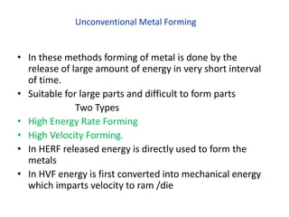
- 1. Unconventional Metal Forming • In these methods forming of metal is done by the release of large amount of energy in very short interval of time. • Suitable for large parts and difficult to form parts Two Types • High Energy Rate Forming • High Velocity Forming. • In HERF released energy is directly used to form the metals • In HVF energy is first converted into mechanical energy which imparts velocity to ram /die
- 2. • HERF • Explosive Forming • Electro Hydraulic Forming • Electro Magnetic • Rate of Energy flow is very high. • Can produce pressure from 700-7000 MPa • HVF • Pneumatic Mechanical forming • Petro forge hammer • Dynapack
- 3. Explosive forming : • Explosive forming is the forming of sheet metal using large amounts of chemical energy from explosive over a very short time . • Sheet-metal blank is clamped over a die. • The die cavity is vacuumed • Assembly is immersed in a tank with water • An explosive charge is detonated under water pushing the sheet in the die in about 2 milliseconds.
- 4. Explosive Forming • This technique uses the energy generated by an explosive detonation to form the metal work piece. This process can deliver a great deal of flexibility in the metal-forming process. • The use of water as the energy transfer medium ensures a uniform transmission of energy and muffles the sound of the explosive blast. The process is versatile – a large variety of shapes can be formed, there is virtually no limit to the size of the work piece, and it is suitable for low – quantity production as well.
- 5. Explosive Forming Common Explosive are • TNT (Tri Nitro Toluene) • Petrolite • RDX(Cyclo Tri Methylene tri Nitramine) Explosive Forming Operations can be divided into two groups, depending on the position of the explosive charge relative to the work piece. • The standoff method (Unconfined System) • The contact method.(Confined System)
- 6. The standoff method(Unconfined System) • The standoff method of explosive forming has the charge located some distance from the workpiece Generally, water is used as way to ensure the even transfer of energy to the workpiece and to reduce noise caused by the explosion. • When the pressure wave (fluid force) expands against the workpiece, the metal is compressed against the form die causing the desired shape to be formed. • Used for large parts ( thickness 25 mm) • Air is highly compressive & • produce lower shockwaves. • Small SOD result in greater Force and hence it is used for deep drawing while large SOD for shallow drawing.
- 7. Standoff Technique The sheet metal work piece blank is clamped over a die and the assembly is lowered into a tank filled with water. The air in the die is pumped out. The explosive charge is placed at some predetermined distance from the work piece, On detonation of the explosive, a pressure pulse of very high intensity is produced. A gas bubble is also produced which expands spherically and then collapses. When the pressure pulse impinges against the work piece, the metal is deformed into the die with as high velocity as 120 m/s.
- 8. Contact Technique.(Confined System) • A die in two more pieces is used which completely encloses the workpiece. • The explosive charge in the form of cartridge is held in direct contact with the work piece while the detonation is initiated. • The detonation builds up extremely high pressures (upto 30,000MPa) on the surface of the work piece resulting in metal deformation, and possible fracture. • All energy is utilized for deformation • The process is used often for bulging tubes, • Drawbacks: Die erosion and Greater Hazard
- 9. Explosive forming is mainly used in the aerospace industries but has also found successful applications in the production of automotive related components. The process has the greatest potential in limited – production prototype forming and for forming large size components for which conventional tooling costs are prohibitively high. Applications.
- 10. • Mainly used for swaging type operations, such as fastening fittings on the ends of tubes and crimping terminal ends of cables. • Tubular work piece is placed in or near a coil, • A high charging voltage is supplied for a short time to a bank of capacitors connected in parallel. • When the charging is complete, which takes very little time, a high voltage switch triggers the stored electrical energy through the coil. • A high – intensity magnetic field is established which induces eddy currents into the conductive work piece, resulting in the establishment of another magnetic field. • The forces produced by the two magnetic fields oppose each other with the consequence that there is a repelling force between the coil • and the tubular work piece that causes permanent deformation of the work piece. Electromagnetic Forming
- 13. Electro hydraulic forming (EHF), OR Electro spark forming, • Electric discharge in the form of spark is used instead of explosive to generate shockwave. • A bank of capacitors is first charged to a high voltage and then discharged across a gap between two electrodes, causing explosions inside the hollow work piece, which is filled with some suitable medium, generally water. • These explosions produce shock waves that travel radially in all directions at high velocity until they meet some obstruction. • If the discharge energy is sufficiently high, the hollow work piece is deformed. • The deformation can be controlled by applying external restraints in the form of die or by varying the amount of energy released,
- 14. • A potential difference of 50 KV when jump a gap of 25 mm discharge takes place , the arc produced , convert water into steam . This generate high pressure which are utilized for forming the w/P • It is safer and lower cost. • Production rate is higher than explosive forming
- 15. Applications forming and assembly operations. It has found extensive applications in the fabrication of hollow, non – circular, or asymmetrical shapes from tubular stock. The compression applications involve swaging to produce compression, tensile, and torque joints or sealed pressure joints, and swaging to apply compression bands or shrink rings for fastening components together. Flat coils have been used on flat sheets to produce stretch (internal) and shrink (external) flanges on ring and disc – shaped work pieces.
- 16. Advantages EHF can form hollow shapes with much ease and at less cost compared to other forming techniques. EHF is more adaptable to automatic production compared to other high energy rate forming techniques. EHF can produce small – to intermediate sized parts that don't have excessive energy requirements. Accuracy of parts produced Accuracy of electro hydraulically formed parts depends on the control of both the magnitude and location of energy discharges and on the dimensional accuracy of the dies used. With the modern equipment, it is now possible to precisely control the energy within specified limits, therefore the primary factor is the dimensional accuracy of the die. External dimensions on tubular parts are possible to achieve within ± 0.05 mm with the current state of technology. Materials formed Materials having low ductility or having critical impact velocity less than 30 m/s are generally not considered to be good candidate for EHF. All materials that can be formed by conventional forming processes can be formed by EHF also. These materials are aluminum alloys, nickel alloys, stainless steels, titanium, and Inconel 718