


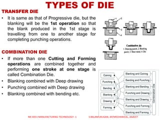


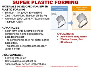
![TUBE BENDING OPERATION
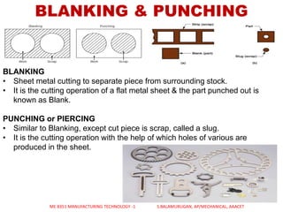
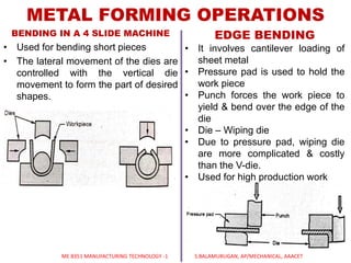
STRAIGHT BENDING
• The work piece, in this case a tube is clamped by
its ends.
• An axial pulling force applied to the pipe as it is
pulled towards and over the template radius so
that the tube is bent by plastic deformation.
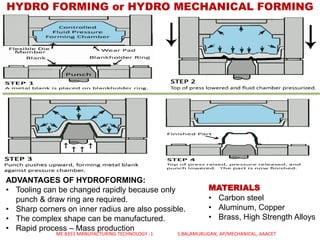
ADVANATGES - Bending without pressing forces in
the material
DISADVANTAGES - Thinner wall thicknesses
required.
COMPRESSION BENDING
• The work piece, in this case a tube pressed by a
pressure bar [1] against the fixed form block [2].
• The wipe shoe [3] is pressed against and drawn
along the radius of the block so as to bend the
tube along its contour by plastic deformation.
• Bending core [4] is used but it’s usually done
without it, thus giving an oval cross section in the
bent area.
ADVANTAGES - Cheap method, Simple tools
DISADVANTAGES - The tube can get deformed -
Limited to certain pipe sizes.
ME 8351 MANUFACTURING TECHNOLOGY -1 S.BALAMURUGAN, AP/MECHANICAL, AAACET](https://image.slidesharecdn.com/sheetmetalprocesses-190920054431/85/Sheet-metal-processes-44-320.jpg)
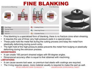
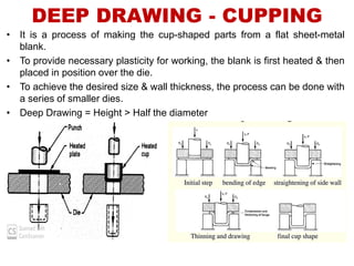
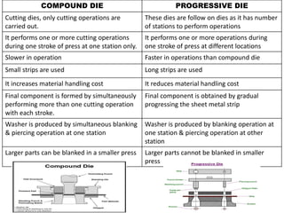
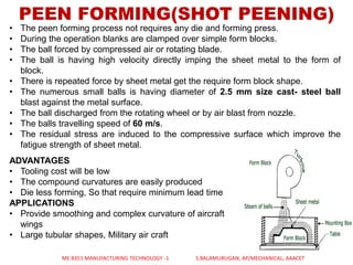
![TUBE BENDING OPERATIONDRAW BENDING
• The work piece or pipe held by clamps [1] to a rotary bending die [2].
• Just behind the clamp enclosing the tube is a sliding pressure die [3] and a stationary
wiper [4].
• When bending, the pipe is rotated along with the rotary bending die around its outline,
while the follower works as a support for the forces that occur when the pipe
undergoes plastic deformation.
• An articulated bending core [5] prevents cross section deformation.
ME 8351 MANUFACTURING TECHNOLOGY -1 S.BALAMURUGAN, AP/MECHANICAL, AAACET
R/D < 3.0, WITH MANDREL
R/D < 1.5, WIHTOUT MANDREL](https://image.slidesharecdn.com/sheetmetalprocesses-190920054431/85/Sheet-metal-processes-45-320.jpg)
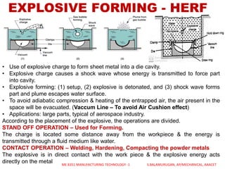
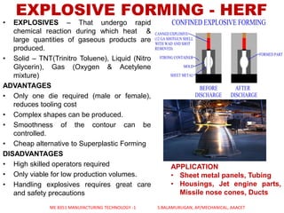
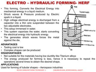
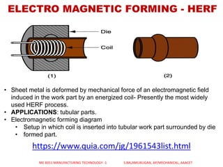


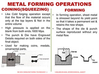
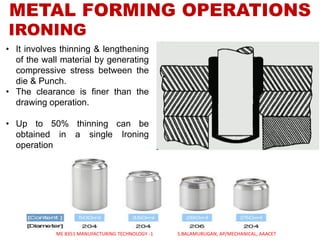
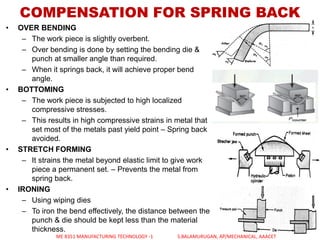
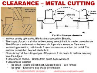
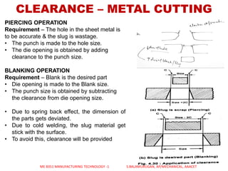
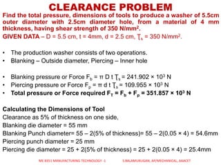
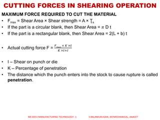
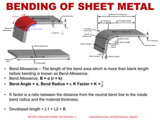
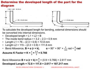
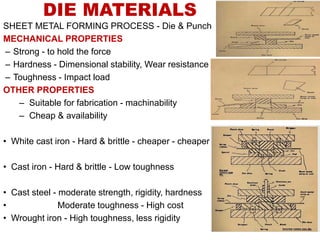
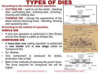
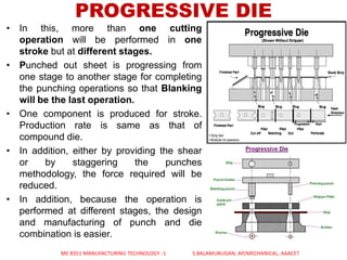
This document discusses sheet metal processes. It begins by defining sheet metal working as a chipless manufacturing process that forms various components from sheet metal using punching and other forming operations. It then discusses various sheet metal cutting operations like blanking and punching as well as forming operations like bending, drawing, and coining. Specific processes like fine blanking, deep drawing, and springback compensation techniques are also covered. The document provides examples of applications for sheet metal working and discusses concepts like tooling dimensions, forces, and developed lengths.


