This document provides an overview of fluid properties and concepts in fluid mechanics. It defines key terms such as:
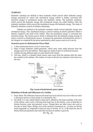
- Density, specific weight, specific volume, viscosity, and other fluid properties.
- Hydrostatic pressure which increases linearly with depth in a static fluid.
- Pascal's law which states that pressure in a static fluid is independent of direction and transmitted equally.
- Total pressure and center of pressure on submerged surfaces, including equations for horizontal, vertical, and inclined planes.

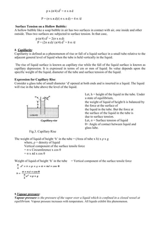
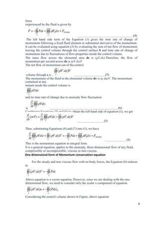
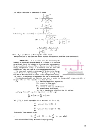
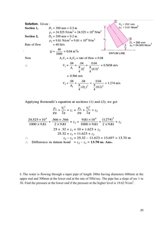
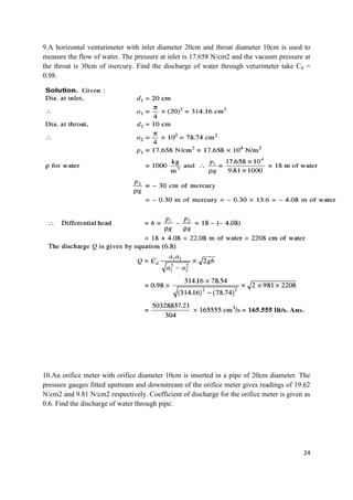
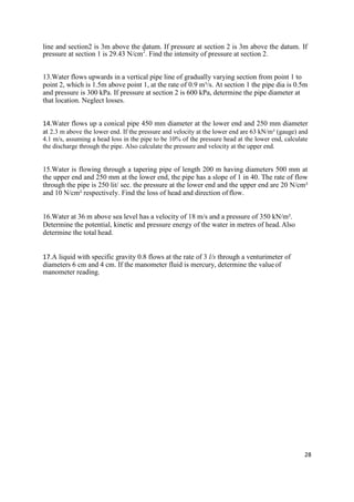
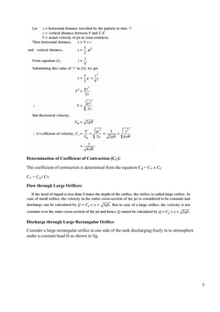
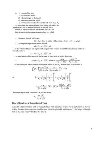
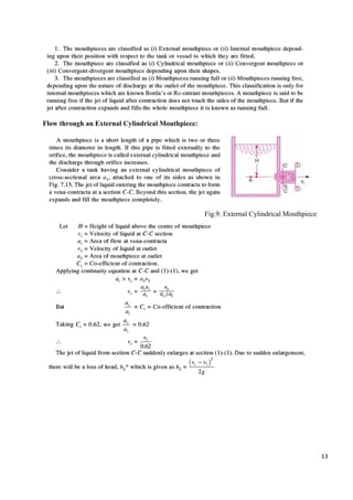
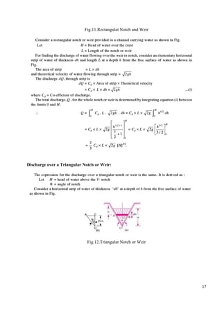
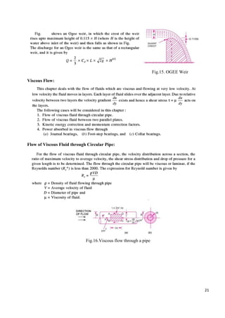
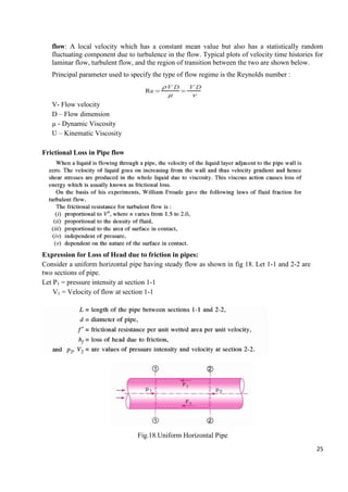
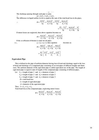
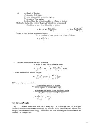
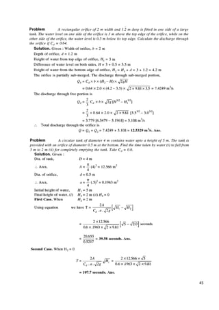
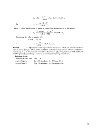
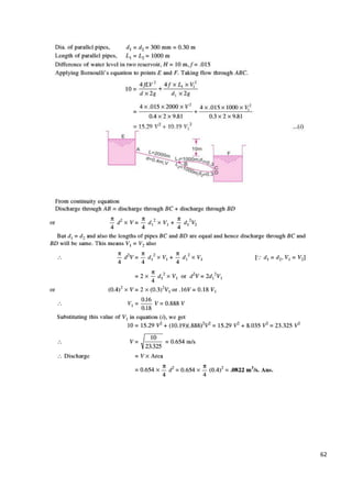
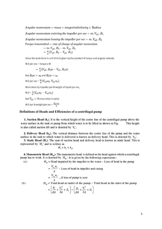
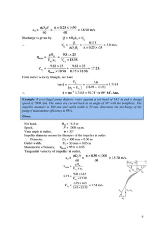
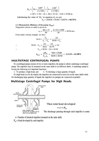
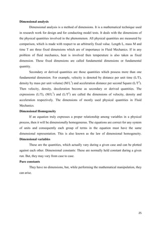
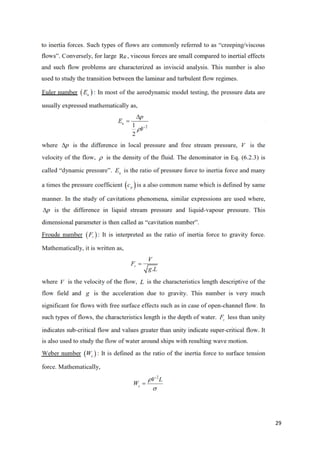
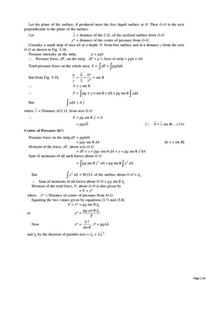
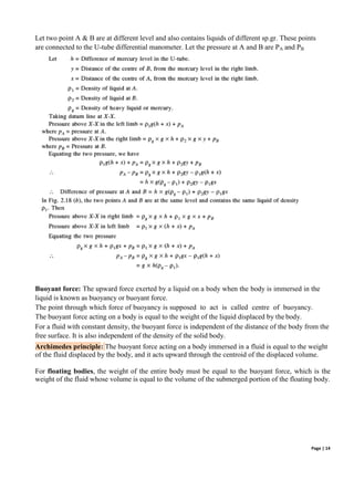
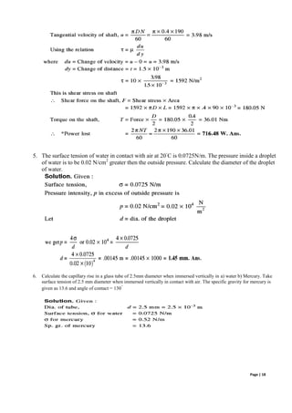
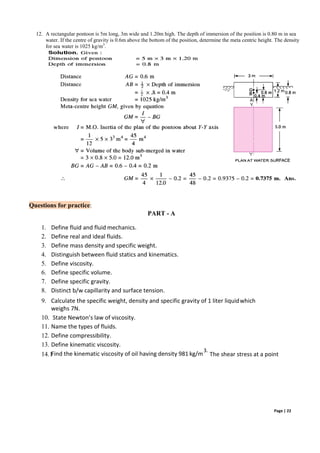
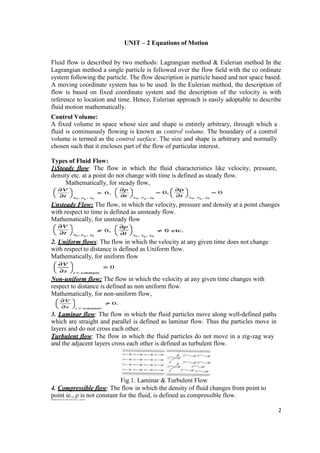
![Let the free surface of the fluid be the origin, i.e., Z = 0. Then the pressure variation at a
depth Z = - h below the free surface is governed by
(p + dp) A + W = pA
dpA + ρgAdz = 0 [W= w x volume = ρg Adz] dp = -ρgdz
= - ρg = - w
Therefore, the hydrostatic pressure increases linearly with depth at the rate of the specific
weight, w = ρg of the fluid.
If fluid is homogeneous, ρ is constant.
By simply integrating the above equation,
ʃdp = - ʃρg dz => p = - ρg Z + C
Where C is constant of integration.
When z = 0 (on the free surface), p = C = po = the atmospheric pressure.
Hence, p = - ρgZ + po
Pressure given by this equation is called ABSOLUTE PRESSURE, i.e., measured above
perfect vacuum.
However, it is more convenient to measure the pressure as gauge pressure by setting
atmospheric pressure as datum pressure. By setting po = 0,
p = -ρgz+0 = -ρgz = ρgh
p = wh
The equation derived above shows that when the density is constant, the pressure in a liquid at
rest increases linearly with depth from the free surface.
Here, h is known as pressure head or simply head of fluid.
In fluid mechanics, fluid pressure is usually expressed in height of fluids or head of fluids.
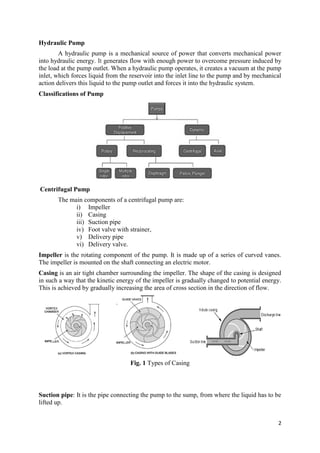
Hydrostatic force
Hydrostatic pressure is the force exerted by a static fluid on a plane surface, when the static
fluid comes in contact with the surface. This force will act normal to the surface. It is also known as
Total Pressure.
The point of application of the hydrostatic or total pressure on the surface is known as Centre of
pressure.
The vertical distance between the free surface of fluid and the centre of pressure is called depth of
centre of pressure or location of hydrostatic force.
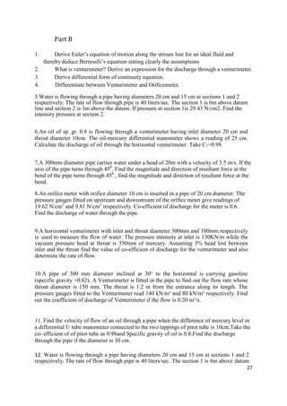
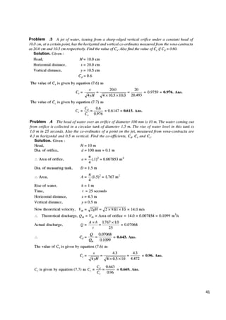
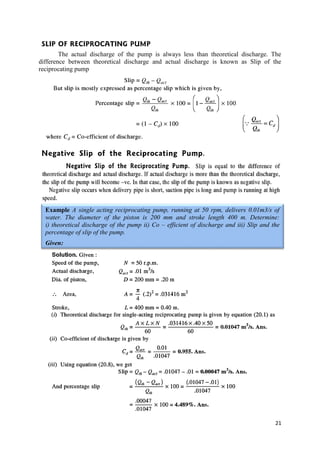
Total Pressure on a Horizontally Immersed Surface
Consider a plane horizontal surface immersed in a liquid as shown in figure.
Let, w = Specific weight of the liquid, kN/m³
A = Area of the immersed surface in m²
= Depth of the horizontal surface from the liquid level in
m We know that,
Total pressure on the surface, P = Weight of the liquid above the immersed surface
Page | 7](https://image.slidesharecdn.com/fmmnotes-231221065040-09465ade/85/fmm-notes-pdf-8-320.jpg)
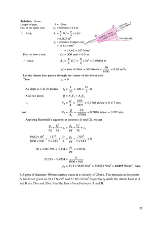
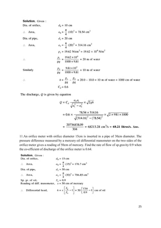
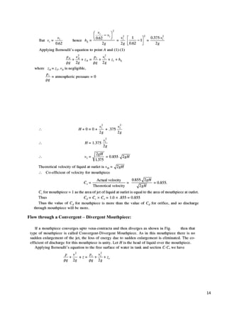
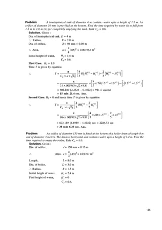
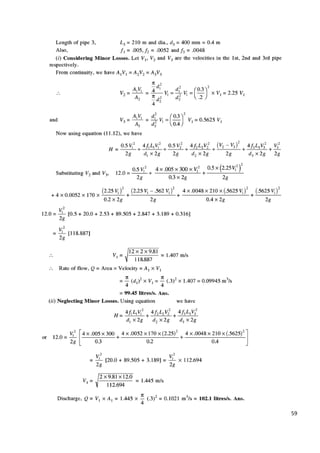
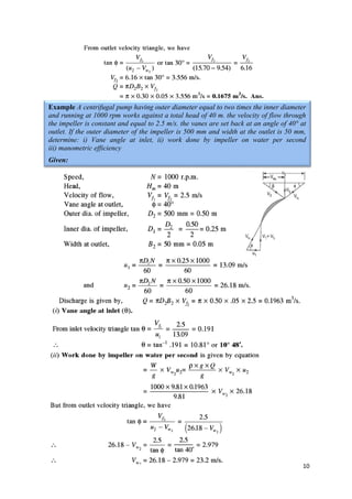
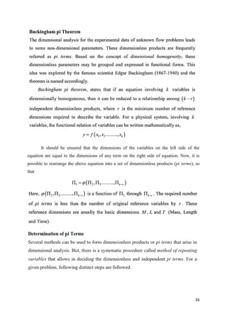
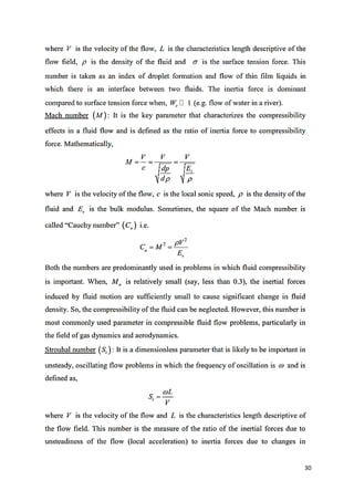
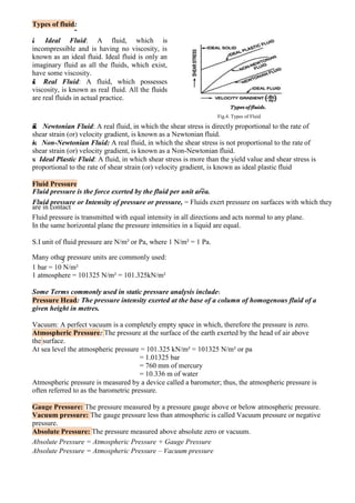
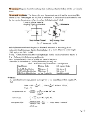
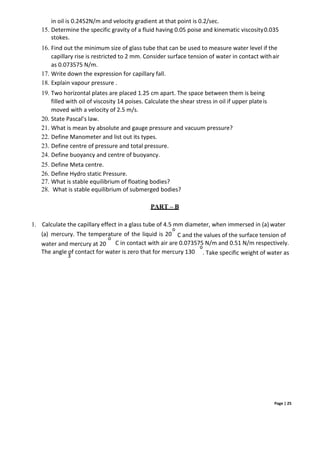
![Page | 9
A x h = (IG + A x
²)
epth of centre of pressure, h
= (IG + A x²) / A
h* = [ (IG + Ah2
)/Ah] + h
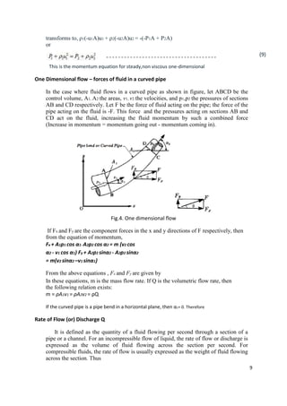
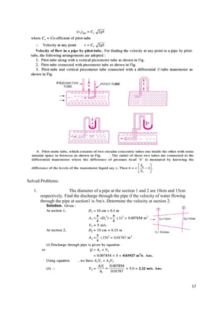
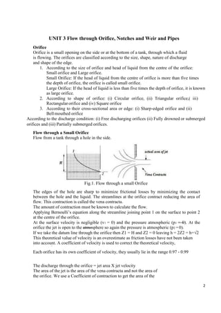
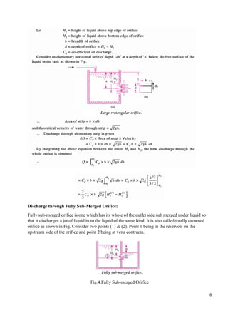
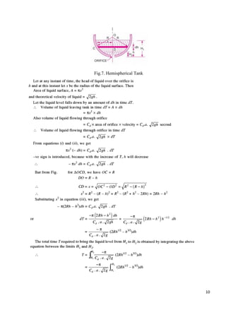
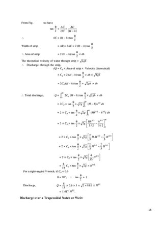
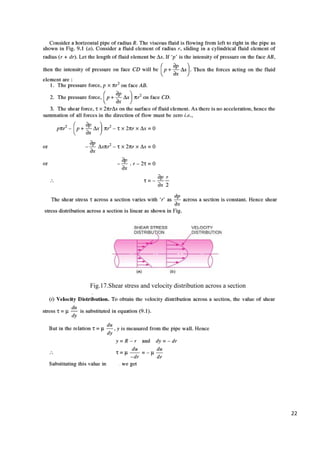
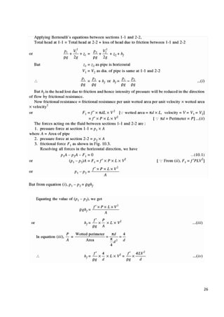
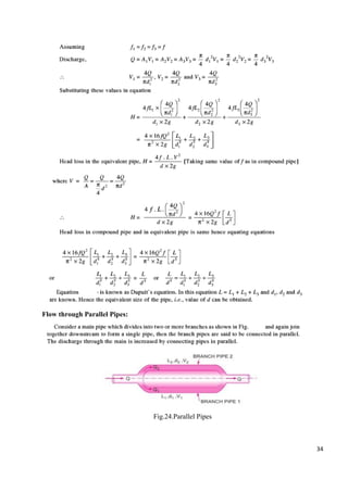
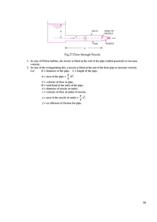
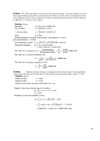
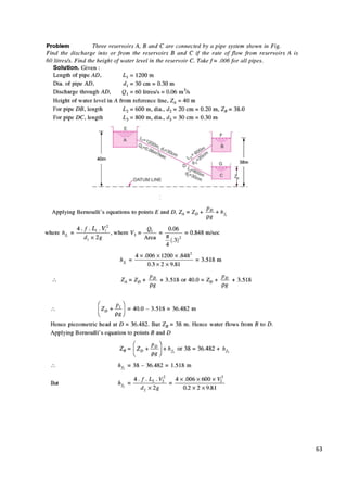
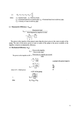
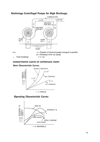
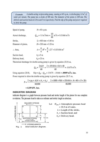
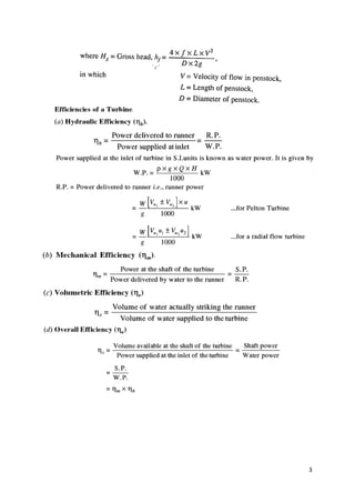
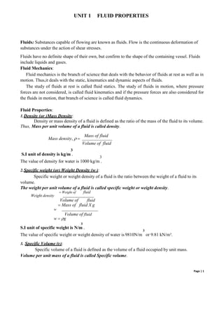
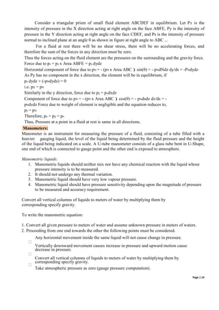
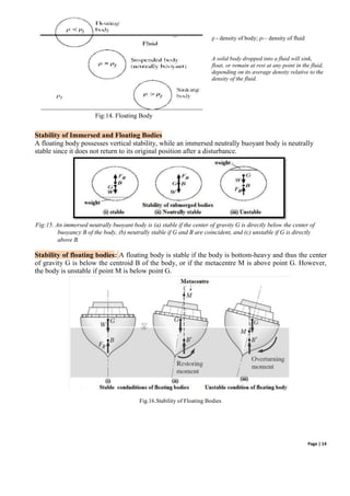
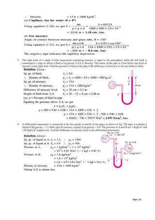
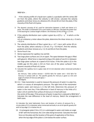
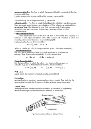
Total Pressure and depth of Centre of Pressure on an Inclined Immersed Surface
Consider a plane inclined surface, immersed in a liquid as shown in figure. Let,
w = Specific weight of the liquid
A = Total area of the immersed surface
x = Depth of the centroid of the immersed plane surface from the free surface of liquid.
θ = Angle at which the immersed surface is inclined with the liquid
surface h
= depth of centre of pressure from the liquid surface
b = width of the considered thin
strip dx = thickness of the strip
O = the reference point obtained by projecting the plane surface with the free surface of liquid
x = distance of the strip from O
Fig: 10. Inclined Immersed Plain](https://image.slidesharecdn.com/fmmnotes-231221065040-09465ade/85/fmm-notes-pdf-10-320.jpg)

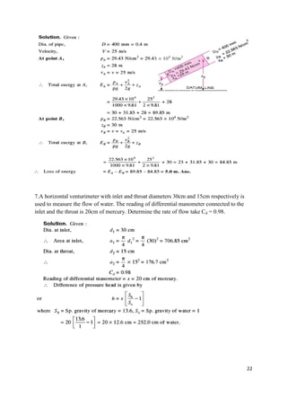
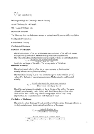
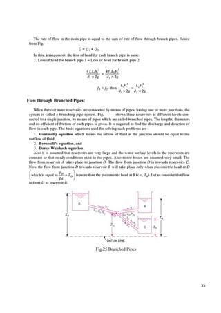
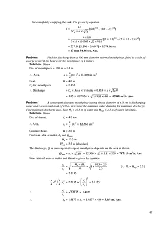
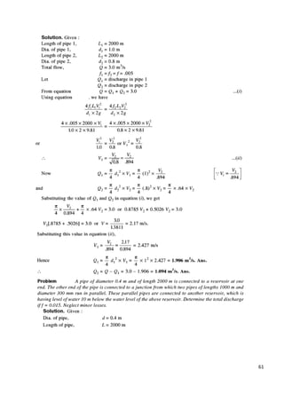
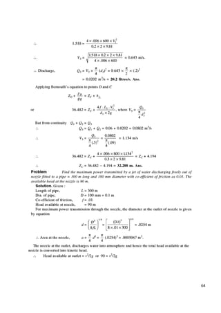
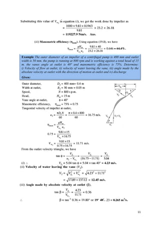
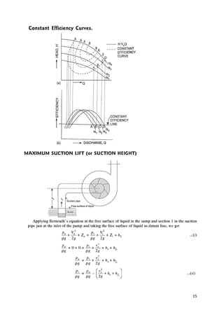
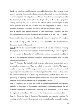
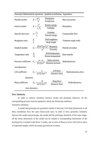
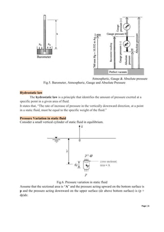
![6
The rate of work done on the elemental
If the flow is viscous, the shear stress on the control surface will also do work on the
fluid as it passes across the surface. Let Wviscous denote the work done due to the
shear stress. Therefore, the total work done on the fluid inside the control volume is
the sum of terms given by (3) and (4) and Wviscous, that is
For the open system considered, the changes in internal energy as well as kinetic
energy need to be accounted. Therefore, right hand side of equation (1) should deal
with total energy (sum of internal and kinetic energies) of the system. Let, e be the
internal energy per unit mass of the system and kinetic energy per unit mass due to
local velocity V be V²/2.
Total energy in the control volume might also change due to influx and outflux of the
fluid. The elemental mass flow across ds is (ρV.ds). Therefore the elemental flow of
total energy across the ds is (ρV.ds)(e+V²/2).
Hence the net energy change of the control volume is,
) -------------------(6)
Thus, substituting Equations (2), (5) and (6) in equation (1), we have
This is the energy equation in the integral form. It is essentially the first law
thermodynamics applied to fluid flow or open system.
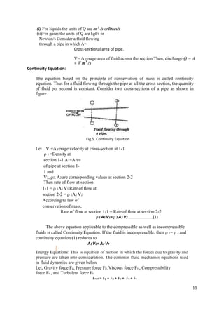
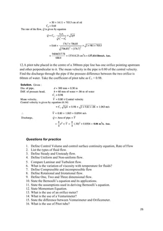
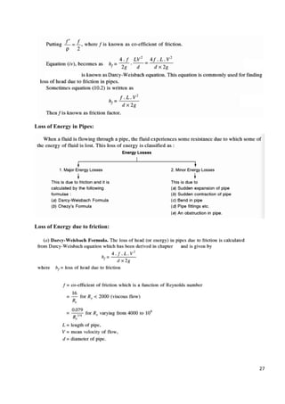
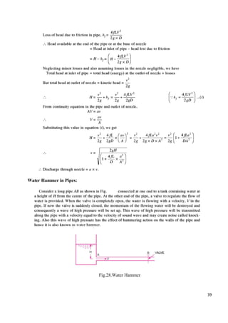
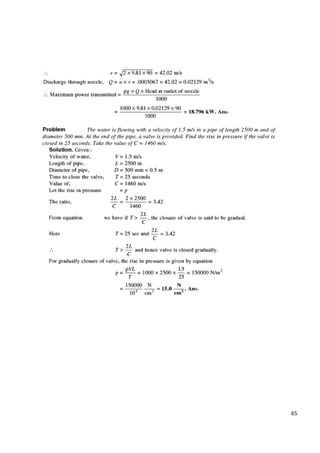
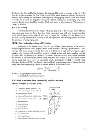
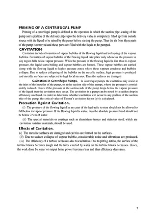
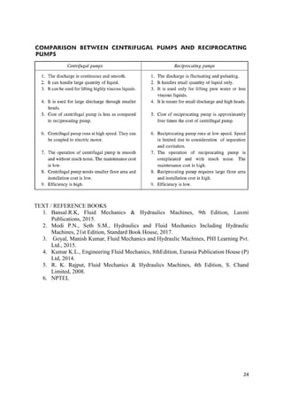
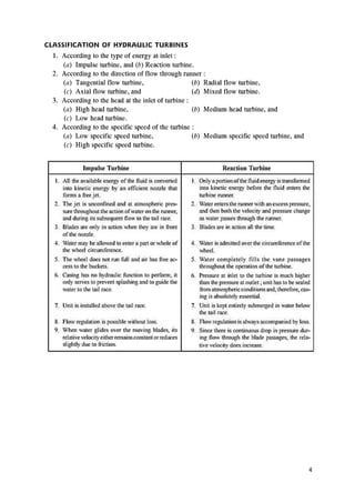
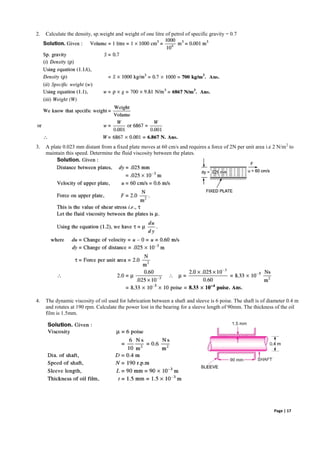
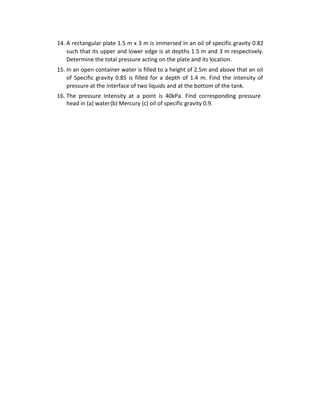
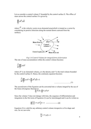
One dimensional form of Conservation of Energy
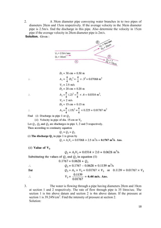
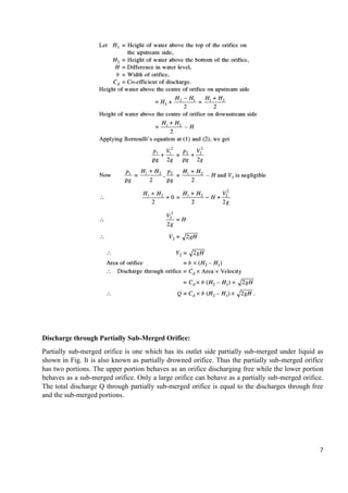
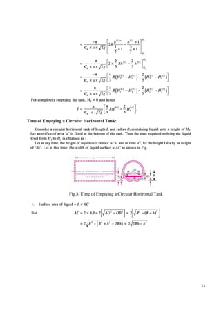
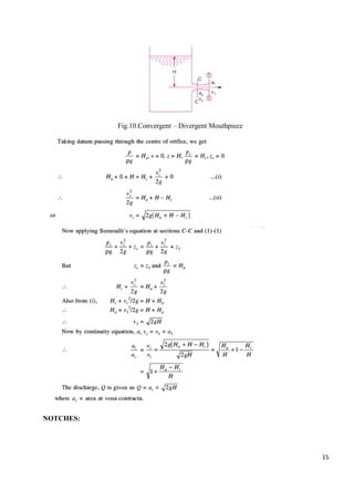
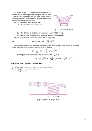
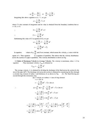
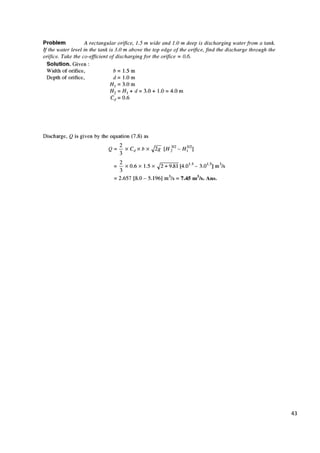
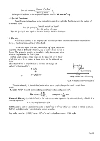
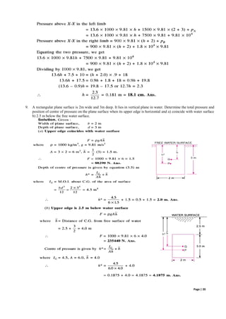
Consider the control volume shown in Figure for steady inviscid flow without
body force, Then the equation (9) reduces to,
Let us denote the first term on left hand side of above equation by to represent
the total external heat addition in the system. Thus, above equation becomes
2
− ∯ = ∯ [ + ]
2
Evaluating the surface integrals over the control volume in Figure, we obtain](https://image.slidesharecdn.com/fmmnotes-231221065040-09465ade/85/fmm-notes-pdf-32-320.jpg)