
Download to read offline
![2 A. Raeisi et al./ Journal of Soft Computing in Civil Engineering 8-4 (2024) 1-26
1. Introduction
The application of fiber reinforced polymer (FRP) reinforcement using the near surface mounted
(NSM) technology has been increasingly prominent in enhancing the strength of reinforced
concrete (RC) elements. The proposed methodology entails the creation of slots within the
concrete cover, followed by the infusion of epoxy as a bonding agent, prior to the installation of
the FRP reinforcement. Several research conducted over the past two decades have examined
and contrasted the effectiveness of this strategy in relation to the externally bonded (EB)
approach. The process of designing externally bonded FRP has been simplified due to the efforts
of many international organizations, such as the American Concrete Institute (ACI) 440.2R-17
[1]. Nevertheless, according to research findings, de-bonding takes place at a low level of tension
between the FRP and concrete surface, despite the broad use of the EB FRP approach. Therefore,
this technique does not allow for the complete realization of the entire potential of FRP [2]. The
advantages of the novel technology in comparison to the preceding (EB) method encompass
enhanced safeguarding, a superior bond, heightened aesthetic appeal, improved surface
preparation, and the possibility of securing attachment to adjacent components [3]. The
enhancement of bond performance, in comparison to EB systems, is a crucial element in the
construction of NSM-FRP systems [4]. Several elements linked to FRP, including the size of the
bars, surface treatment, groove geometry, concrete properties, and adhesive used in the test setup,
have been found to affect the bond between concrete and NSM FRP bars [5,6]. Over the course
of the last ten years, there have been notable advancements in the near surface mounted
technique, including the development of novel anchorage methods [7], and the utilization of
cost-effective materials for manufacturing FRP bars at building sites [8]. The application of FRP
systems to reinforce a bridge slab in the negative moment zone was first observed in northern
Sweden during the 1940s, as documented by Asplund in 1949, in this particular process, the steel
rods were incorporated into the concrete cover using cement mortar [9]. Four slabs were
subjected to experimental reinforcement using an identical technique prior to the commencement
of the strengthening procedure. Subsequently, these slabs were subjected to loading until failure
occurred. In March 1949, an experiment was conducted where approximately 600 meters of steel
bars were successfully bonded to the concrete cover. The results of this experiment provided
evidence of the efficacy of this strategy. It is important to acknowledge that the establishment of
a successful concrete cover bond in these projects presents a complex undertaking, as there may
be instances where it is not feasible to pour concrete around the reinforcement bars [10]. A
preliminary investigation on flexural strength of beam strengthened with NSM technique
conducted at Lule University of Technology in 1996 assessed the initial rectangular FRP rods. In
conjunction with a comprehensive investigation conducted by Lorenzis et al. [4], as well as the
work of Hassan and Rizkalla et al [11] examined circular rods in 2001, the results demonstrated a
significant enhancement in capacity, with improvements ranging from 25.7% to 44.3% compared
to the control beam. However, it is evident that establishing a strong bond is crucial for the
efficacy of this technique. The research undertaken by Nordin and Täljsten [12] revealed that the
sawing of grooves for FRP reinforcement was only feasible when the steel reinforcement has an
adequate level of "depth."](https://image.slidesharecdn.com/sccevolume8issue4pages1-26-250603072131-8b2b23e2/75/Flexural-Capacity-Prediction-of-RC-Beams-Strengthened-in-Terms-of-NSM-System-Using-Soft-Computing-2-2048.jpg)
![A. Raeisi et al./ Journal of Soft Computing in Civil Engineering 8-4 (2024) 1-26 3
Fig. 1. Concrete member strengthened in flexure with NSM FRP.
It is imperative to acknowledge that the efficacy of this technique is contingent upon the
thickness of the concrete cover, a parameter that exhibits variability based on the prevailing
conditions encountered at the construction site. Hence, it may be inferred that outdoor structures,
particularly bridges, may derive greater advantages from the suggested technique in comparison
to inside ones, owing to their higher concrete coverage [9]. According to recent researches
[13,14], examinations have shown that the use of NSM-FRP rods in reinforced concrete beams
might potentially increase the Flexural Strength by up to 60.6%. This enhancement is dependent
on the specific ratios of internal steel reinforcement and the subsequent behavior of the beams.
The researchers investigated the bonding mechanism between NSM-FRP bars and its
implications for flexural strengthening in concrete structures. The study stated earlier made
predictions on the bond length limitations for each side of the beam's center line, with a clear
span of 2500 millimeters. These limitations were estimated to be 150, 550, 800, and 1200
millimeters [15]. The results of the study indicate that the optimal development length for NSM-
CFRP should not be reduced to a value less than 80 times the initial diameter, taking into account
the specific properties of the materials and grooves employed. Conversely, the reinforced beams
exhibited minimal reduction in ultimate load capacity when subjected to the modified epoxy
adhesive. Furthermore, it was observed that the load capacity of the beams exhibited a modest
improvement when the bond lengths exceeded 800 millimeters [16]. According to the results of
the beam bond experiment conducted in reference [17], it was observed that longer rod bonds
were associated with an augmented ultimate load capacity. Consequently, the resistance to
splitting was enhanced through the process of widening the square grooves. In a previous study
[18], the beams, which had a distinct span of 2800 millimeters, were reinforced by employing
adhesive bonds with lengths measuring 2100, 2700, and 3000 millimeters. The utilization of](https://image.slidesharecdn.com/sccevolume8issue4pages1-26-250603072131-8b2b23e2/75/Flexural-Capacity-Prediction-of-RC-Beams-Strengthened-in-Terms-of-NSM-System-Using-Soft-Computing-3-2048.jpg)
![4 A. Raeisi et al./ Journal of Soft Computing in Civil Engineering 8-4 (2024) 1-26
epoxy in the NSM system led to the breakdown of the system, resulting in the withdrawal of the
rods and the detachment of the concrete cover from the end of the rods. In spite of the observed
elongation of 3000 millimeters in the bond length, there was no discernible reduction in the
maximum load deflection. Furthermore, the strength of the concrete had minimal influence on
the load-carrying capacity of the reinforced beams [19].A subsequent investigation in this field
examined the application of reinforced beams with less robust bonding, resulting in significant
implications for failure modes such as the detachment of concrete or the extraction of CFRP
rods. Furthermore, the cantilever beams that were reinforced and subjected to testing using a
four-point flexure exhibited identical failure mechanisms, as reported in a previous study [20].
Based on the findings of a separate study [21], the utilization of CFRP strips as near-surface
mounted (NSM) reinforcements, as opposed to EB-CFRP strips, resulted in a significant
enhancement of the load-bearing capacity of reinforced beams, with an increase of 4.8 times.
However, according to a recent study, the utilization of NSM CFRP strips to reinforce GFRP RC
beams may eventually change the failure mode compared to the beams without reinforcement,
resulting in more vulnerable failure modes such CFRP rupture or CFRP debonding [22].
2. Analytical approach
The Figure.2 shows the basic theoretical conditions of internal strain, stress, in the ultimate
section that is under-reinforced with steel ( s sb
ρ < ρ ), and it is strengthened by FRP. The essential
assumptions for this condition are: throughout the cross section, the strain changes linearly, the
section is not cracked at initial, there is a complete bond between the steel and FRP
reinforcements and concrete, 0.003 is the level of concrete strain where the compression failure
occurs, and in the compression area, the Whitney rectangular stress block considered a good
substitution for the nonlinear distribution of stress at ultimate, and Finally, the behavior of steel
is considered elastic-plastic in terms of stress-strain [6].
Fig. 2. Model analysis at ultimate [4].
Since the section is not cracked at first and f s
d > d , the FRP strain f
ε will be almost higher than
the steel strain s
ε . There is a dependency between the nominal flexural uncracked beam strength](https://image.slidesharecdn.com/sccevolume8issue4pages1-26-250603072131-8b2b23e2/75/Flexural-Capacity-Prediction-of-RC-Beams-Strengthened-in-Terms-of-NSM-System-Using-Soft-Computing-4-2048.jpg)
![6 A. Raeisi et al./ Journal of Soft Computing in Civil Engineering 8-4 (2024) 1-26
Likewise, the steel stress is y
f when s sy
A A
. However, in case of s sy
A > A , the steel stress is less
than y
f and have to be calculated by compatibility and equilibrium. By use of this method, in all
samples controlled by concrete failure in this study the ultimate steel stress was equal to yield.
While the steel stress is equal to yield, for the sections controlled by concrete failure, the
compression block (a), FRP reinforcement stress ( f
f ), and nominal moment capacity ( n
M ) can
be obtained from the following equations:
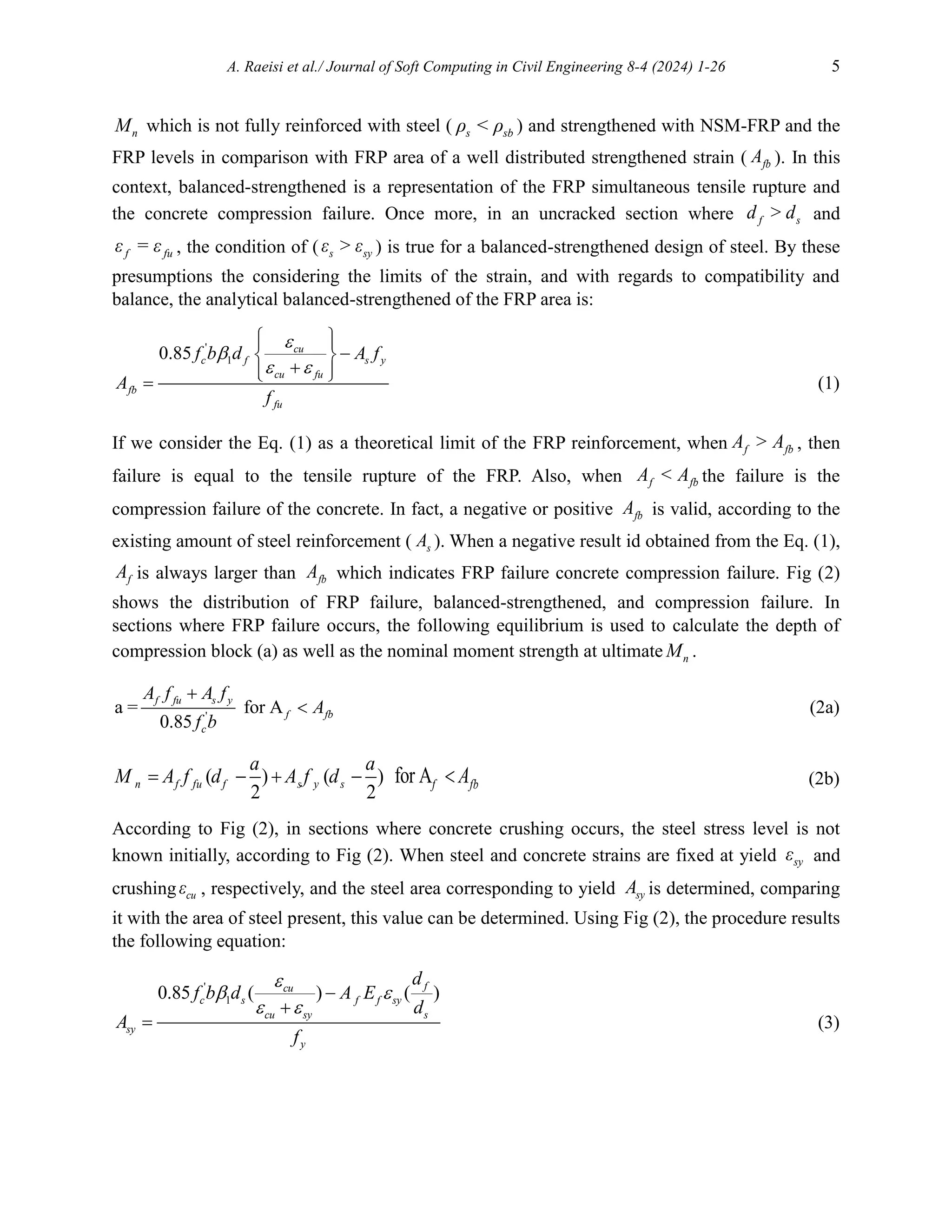
2 '
1
'
( ) 4(0.85) ( )
(2)0.85
f f cu s y c f f sy f f f cu s y
c
A E A f f b A E d A E A f
a
f b
(4a)
1
1
f
f f cu fu
d
f E f
(4b)
( ) ( )
2 2
u f f f s y s
a a
M A f d A f d
(4c)
3. Artificial neural networks methodology
Artificial neural networks are not commonly employed for the purpose of estimating the capacity
of civil engineering structures. However, their inherent capability to effectively identify and
replicate patterns renders them an ideal tool for undertaking such a task [23]. In the context of
FRP strengthening of RC beams, these models assume a highly specialized role since they
possess the capability to address intricate issues that prove challenging to resolve by analytical
methods [24]. This is particularly true in cases when there is a lack of fundamental physical or
mathematical models to guide the resolution of these challenges. Neural-network modelling, a
nonlinear regression model utilized in the life sciences, is grounded on the basic mechanisms of
the human brain [25]. Figure 3 illustrates the representation of typical computational neurons.
The computational neuron possesses analogous characteristics to biological neurons, including
an input, a nerve cell, and an output. The primary step in the modelling of neural networks in the
present study involved the collection of homogeneous experimental data through a
comprehensive analysis of previous studies and identified and selected the variables that have a
significant impact on the outcome. These variables were subsequently designated as input nodes
in the modelling procedure. In a neural network architecture, a node situated on a distinct layer is
responsible for receiving a collection of input values and generating a linear output by utilizing
weights and biases [26]. Neurons exhibit binary activation states, determined by an activation
function. The primary objective of the activation function is to derive non-linear output from a
linearly generated value. The Sigmoid, Tanh, and Rectified Linear Unit (ReLU) functions are
widely recognized as the three most prominent activation functions in the field [25]. In the
domain of civil engineering, it has been observed that the Tanh function exhibits superior
performance compared to alternative activation functions when employed as the output layer](https://image.slidesharecdn.com/sccevolume8issue4pages1-26-250603072131-8b2b23e2/75/Flexural-Capacity-Prediction-of-RC-Beams-Strengthened-in-Terms-of-NSM-System-Using-Soft-Computing-6-2048.jpg)
![A. Raeisi et al./ Journal of Soft Computing in Civil Engineering 8-4 (2024) 1-26 7
activation function [27]. In order to enhance the predictability of the proposed prediction model,
several neurons were interconnected to create an Artificial Neural Network (ANN).
Fig. 3. Schematic of computational neurons [28].
This neural network consists of one or more hidden layers, an output layer, and a multilayer
perceptron. The architecture of a multilayer perceptron is seen in Figure 5. The architecture of
artificial neural network (ANN) models has a significant impact on their implementation [29].
While there exist alternative training processes, the backpropagation (BP) algorithm is generally
known to produce satisfactory outcomes [30]. The Levenberg-Marquardt method is often
employed as a post-release training algorithm [24]. Prior to the training phase, the acquired data,
consisting of inputs and targets, undergoes normalization or scaling based on known
relationships. This is achieved by reducing the disparity between the values of the variables
under examination across different scales. The equation, denoted as Eq. (1), is employed to
standardize relationships, wherein the values are confined within the range of 0.1 to 0.9, as
observed in the relationships enumerated below:
𝐼𝑆 =
(0.9−0.1)(𝐼−𝐼𝑚𝑖𝑛)
𝐼𝑚𝑎𝑥−𝐼𝑚𝑖𝑛
+ 0.1 (5)
The Levenberg-Marquardt method is utilized to randomly create three sets of input and target
vectors, namely training, validation, and test sets. Various relative percentages are commonly
considered, but, in order to optimize the distribution of the dataset, the training, validation, and
testing subsets are typically allocated 70%, 15%, and 15% respectively [31]. The termination
criterion for network training is determined by the mean square error, specifically by evaluating
the squared difference between the network's outputs and the desired objectives. Lower mean
squared error (MSE) values are associated with improved network performance. Regression
values, which assess the degree of correlation between the outputs of a network and its targets,
have become the prevailing criterion for selecting the appropriate stopping point for a network.
Regression coefficients with a value of 1 indicate a substantial association, whereas regression
coefficients with a value of 0 imply a chance occurrence. By considering these two parameters,
one may effectively determine the optimal network [32]. The formation of the optimal network
occurs through the selection of desirable networks and the careful consideration of the
aforementioned criteria.
∑ Transfer
Output
.
.
.
.
.
.
Bias](https://image.slidesharecdn.com/sccevolume8issue4pages1-26-250603072131-8b2b23e2/75/Flexural-Capacity-Prediction-of-RC-Beams-Strengthened-in-Terms-of-NSM-System-Using-Soft-Computing-7-2048.jpg)
![8 A. Raeisi et al./ Journal of Soft Computing in Civil Engineering 8-4 (2024) 1-26
Fig. 4. A present research program flow chart consists of the proposed model.
As previously mentioned, in this study a feed forward MLP neural network was employed,
consisting of three layers: input, hidden, and output. The input layer represents the characteristic
properties of the behavior of strengthened beams. Given the significant impact of numerous
elements on the Flexural failure mode, it is imperative to meticulously pick input variables or
signatures to achieve an optimal configuration of the Artificial Neural Network (ANN). This is
due to the necessity of selecting the number of input parameters in accordance with the quantity
of training data. In order to accurately describe the system, a multitude of parameters must be
carefully selected. However, it has been established that an increased quantity of input neurons
has a detrimental effect on the efficiency and accuracy of the training process in artificial neural
networks (ANNs).
The activation functions of tan-sigmoid and linear are employed in their respective activation
functions. Training trials were employed to find the optimal number of hidden layer nodes and
determine the most suitable activation functions. The programming language MATLAB was
utilized to develop, train, and deploy an Artificial Neural Network (ANN) employing the back-
propagation technique and the Levenberg-Marquardt training algorithm. The artificial neural
network (ANN) was trained iteratively with the objective of minimizing the performance
function, namely the mean square error (MSE), between the network outputs and the associated
goal values. In a general trend, it was observed that increasing the number of input-target
pairings used during the training process resulted in a higher level of generalization capacity for
the training artificial neural network (ANN) [33].
Start
Investigation of the Flexural
strength of NSM
strengthened Beams
Collection of available
experimental data
Classification and
preparation of Database
Select input parameters
Launching and developing
proposed models based on
artificial neural networks
Verification with test data
Verification
with
experimental
data
Compare results with
existing equations
End
No
Yes](https://image.slidesharecdn.com/sccevolume8issue4pages1-26-250603072131-8b2b23e2/75/Flexural-Capacity-Prediction-of-RC-Beams-Strengthened-in-Terms-of-NSM-System-Using-Soft-Computing-8-2048.jpg)
![A. Raeisi et al./ Journal of Soft Computing in Civil Engineering 8-4 (2024) 1-26 9
Fig. 5. ANN Model Architecture.
4. Database and models
In order to configure and train the ANN, 171 experimental tests collected from 39 NSM-FRP-
flexural strengthened concrete beams experimental articles [2,13,38–47,14,48–57,16,58–
65,20,21,34–37]. Table 1 shows the database sample. With regards to the beam geometric ratios,
ratios of reinforcement, the characteristics of the materials and failure loads the chosen dataset
show a high diversity. The database was categorized randomly into three sets: A training set that
contained 70% beams, a validating set using 15% of the beams, and a test set with 15% total
data. The input and output data were scaled between the interval [0.1, 0.9], in order to prohibit
the slow learning rate of at the end points.
5. Prediction of the flexural capacity of NSM-FRP strengthened RC beams
using ANNs
For the data set related to the beam flexural capacity presented here, just 1 output node was
configured in the ANN. However, as previously mentioned among the large range of elements
influencing the behavior of this strengthening approach, the correct selection of the input
parameters is essential for a successful procedure. As a result, we divided the process of
configuring and training the ANN into two steps. After a thorough analysis of the literature in the
first phase, fifteen parameters were selected for the input: (a) beam geometry, which was either
rectangular or T section, (b) NSM-FRP reinforcement f
ratio, (c) cm
f (concrete average
compressive strength) (d) /
a d shear span/depth ratio, (e) distance between FRP bars edge to
support d
L ,(f) elastic modulus of the FRP reinforcement 1
w , (g) design yielding stress of the
steel reinforcement sy
f , (h) FRP length FRP
L , (i) ratio of the steel shear reinforcement sw
, (j)
ratio of the steel longitudinal reinforcement sl
, (k) height of the beam section h , (l) length of
the beam B
L , (m) FRP ultimate strength fu
f (n) width of the beam cross section w
b (o) and
elastic modulus of the steel reinforcement s
E .
Input layer Hidden layer 1 Hidden layer 2 Output layer
Geometry
Input
weight
Output Flexural
Strength
.
.
.
.
.
.
.
.
.
.
.
.
.
.
.
.
.
.
.
.
.
.
.
.
.
.
.
.
.
.
.](https://image.slidesharecdn.com/sccevolume8issue4pages1-26-250603072131-8b2b23e2/75/Flexural-Capacity-Prediction-of-RC-Beams-Strengthened-in-Terms-of-NSM-System-Using-Soft-Computing-9-2048.jpg)
![10 A. Raeisi et al./ Journal of Soft Computing in Civil Engineering 8-4 (2024) 1-26
Table 1
Flexural Database Sample.
Authors Label
Shape
(T, R)
w
b
(mm)
h
(mm)
B
L
(mm)
FRP
L
(mm)
cm
f
(MPa)
fu
f
(MPa)
sy
f
(MPa)
f
E
(GPa)
s
E
(GPa)
f
sl
sl
Hassan and Rizkalla
2003 [66]
B1 T 150 300 2700 150 48 2000 400 150 200 0.0003 0.0057 0.0042
B2 T 150 300 2700 250 48 2000 400 150 200 0.0003 0.0057 0.0042
B3 T 150 300 2700 500 48 2000 400 150 200 0.0003 0.0057 0.0042
B4 T 150 300 2700 750 48 2000 400 150 200 0.0003 0.0057 0.0042
B5 T 150 300 2700 850 48 2000 400 150 200 0.0003 0.0057 0.0042
B6 T 150 300 2700 950 48 2000 400 150 200 0.0003 0.0057 0.0042
B7 T 150 300 2700 1050 48 2000 400 150 200 0.0003 0.0057 0.0042
B8 T 150 300 2700 1200 48 2000 400 150 200 0.0003 0.0057 0.0042
El-Hacha et al.
2005 [6]
B1 T 150 300 2700 2400 45 1408 400 122.5 200 0.0009 0.008 0.0071
B2 T 150 300 2700 2400 45 1525 400 140 200 0.008 0.008 0.0071
B3 T 150 300 2700 2400 45 2000 400 150 200 0.007 0.008 0.0071
B4 T 150 300 2700 2400 45 1000 400 45 200 0.0025 0.008 0.0071
Barros et al.
2004 [19]
V1R1 R 100 170 1600 1400 46.1 2740 618 158 200 0.0009 0.0038 0.0067
V2R2 R 100 170 1600 1400 46.1 2740 618 158 200 0.0019 0.0057 0.0067
V3R3 R 100 170 1600 1400 46.1 2740 618 158 200 0.0019 0.0071 0.0067
V4r4 R 100 170 1600 1400 46.1 2740 618 158 200 0.0028 0.01 0.0067
Jung et al.
2005 [67]
CRD-NSM R 200 300 3000 2700 31.3 1878 426 121.42 200 0.0012 0.004 0.0077
NSM-PL-25 R 200 300 3000 2700 31.3 2453 426 165.49 200 0.0006 0.004 0.0077
NSM-PL-15 R 200 300 3000 2700 31.3 2453 426 165.49 200 0.0004 0.004 0.0077
ROD-Ml-20 R 200 300 3000 2700 31.3 1878 426 121.42 200 0.0012 0.004 0.0077
PL-Ml-20 R 200 300 3000 2700 31.3 2453 426 165.49 200 0.0006 0.004 0.0077
Nordin and Täljsten
2006 [12]
BS1 R 200 300 4000 3200 64 2800 496 160 210 0.0019 0.0077 0.0077
BS2 R 200 300 4000 4000 62 2800 496 160 210 0.0019 0.0077 0.0077
BM1 R 200 300 4000 3200 64 2800 496 250 210 0.0019 0.0077 0.0077
BM2 R 200 300 4000 4000 65 2800 496 250 210 0.0019 0.0077 0.0077
Teng et al.
2006 [9]
B500 R 150 300 3200 500 35.2 2068 532 131 210 0.008 0.0056 0.0026
B1200 R 150 300 3200 1200 35.2 2068 532 131 210 0.008 0.0056 0.0026
B1800 R 150 300 3200 1800 35.2 2068 532 131 210 0.008 0.0056 0.0026
B2900 R 150 300 3200 2900 35.2 2068 532 131 210 0.008 0.0056 0.0026
Tang et al.
2006 [17]
SPA40-G5-A R 180 250 1500 1500 21 512 398 64 252 0.0106 0.0106 0.0014
SPA20-G5-A R 180 250 1500 1500 37 512 398 64 252 0.0106 0.0106 0.0014
SPA20-G3-A R 180 250 1500 1500 37 650 398 64 252 0.0037 0.0106 0.0014
SNC-G5-A R 180 250 1500 1500 58 512 398 64 252 0.0106 0.0106 0.0014
SNC-G5-B R 180 250 1500 1500 58 512 398 64 252 0.0106 0.0106 0.0014
Al-Mahmoud et al.
2009 [63]
B1 T 150 400 4000 4000 49.5 2068 558 131 210 0.0005 0.0033 0.0031
B2 T 150 400 4000 4000 52.8 2068 558 131 210 0.0005 0.0033 0.0031
C1 T 150 400 4000 4000 52.7 1970 558 147 210 0.0004 0.0033 0.0031
C2 T 150 400 4000 4000 50.1 1970 558 147 210 0.0004 0.0033 0.0031
D1 T 150 400 4000 4000 50.1 690 558 40.8 210 0.0013 0.0033 0.0031
D2 T 150 400 4000 4000 35.2 690 558 40.8 210 0.0013 0.0033 0.0031
Barros and Kotynia
2008 [68]
S1 R 120 170 1000 1000 44.2 2740 788 158.8 200 0.0009 0.0025 0.0025
S2 R 120 170 1000 1000 44.2 2740 627 158.8 200 0.0017 0.0043 0.0025
S3 R 120 170 1000 1000 44.2 2740 627 158.8 200 0.0026 0.0064 0.0025](https://image.slidesharecdn.com/sccevolume8issue4pages1-26-250603072131-8b2b23e2/75/Flexural-Capacity-Prediction-of-RC-Beams-Strengthened-in-Terms-of-NSM-System-Using-Soft-Computing-10-2048.jpg)
![A. Raeisi et al./ Journal of Soft Computing in Civil Engineering 8-4 (2024) 1-26 11
Through randomly choosing the training sample and applying the sensitivity analysis (Milne
index) to every model that satisfied the primary criteria, A preliminary filter was applied to the
input parameters. Using operations between the weight matrices produced in two adjacent layers
of the ANN, the Milne index may determine the relative importance of all input variables in
relation to the output variable [29]. The strategy can be helpful in situations where the index
differs significantly amongst the trained networks. On the other hand, if an input parameter's
index remains low across a large number of networks, it suggests that the parameter is irrelevant
and should be removed.
Fig. 6. Specific details of the proposed ANN Model.
The beam length and the steel reinforcement's Es
elastic modulus was removed in the first
phase. The following condition involved a parametric analysis to assess how well each trained
network can depict the impact of each specific input parameter on the beam capacity. These
investigations were carried out by altering one input parameter while leaving the other
unchanged. The effectiveness of different ANNs in mimicking the physical behavior of the
flexural strengthening of an RC beam was confirmed by parameter analysis. Additionally, for
every set of input parameter, there were between 8 and 20 hidden nodes, and training was carried
out for every possible configuration. /
a d shear span/depth ratio and ratio of the steel shear
reinforcement sw
were found to be less effective in ANN at the second phase. The final 10
variables were used as input variables. For each network, the mean square error between its
output after training and the associated target values in the training and validation sets is initially
estimated. The MSE value was smaller, hence the evaluated network received a higher point. The
ANNs whose predictions agreed with the results of the experimental testing would produce
Start
Data Collection
Select the Input Parameters
Beam
Geometry
NSM-
FRP
ratio
concrete
strength
shear
span/dep
th ratio
FRP
elastic
modulus
FRP
length
shear
ratio
(steel)
longitudi
nal ratio
(steel)
FRP
ultimate
strength
Target = Flexural Strength of Reinforced Beam
ANN
Data Normalization
Divide the Data into Sets
Creating a feed forward-back
propagation neural network
Update number of nodes
Train the network
Obtain the new Model
Calculate Correction Factors
Select reference values
Is network criteria
satisfied
Check the criteria
Verify against experimental
Data
Compare with the existing
models
End
Yes
No](https://image.slidesharecdn.com/sccevolume8issue4pages1-26-250603072131-8b2b23e2/75/Flexural-Capacity-Prediction-of-RC-Beams-Strengthened-in-Terms-of-NSM-System-Using-Soft-Computing-11-2048.jpg)
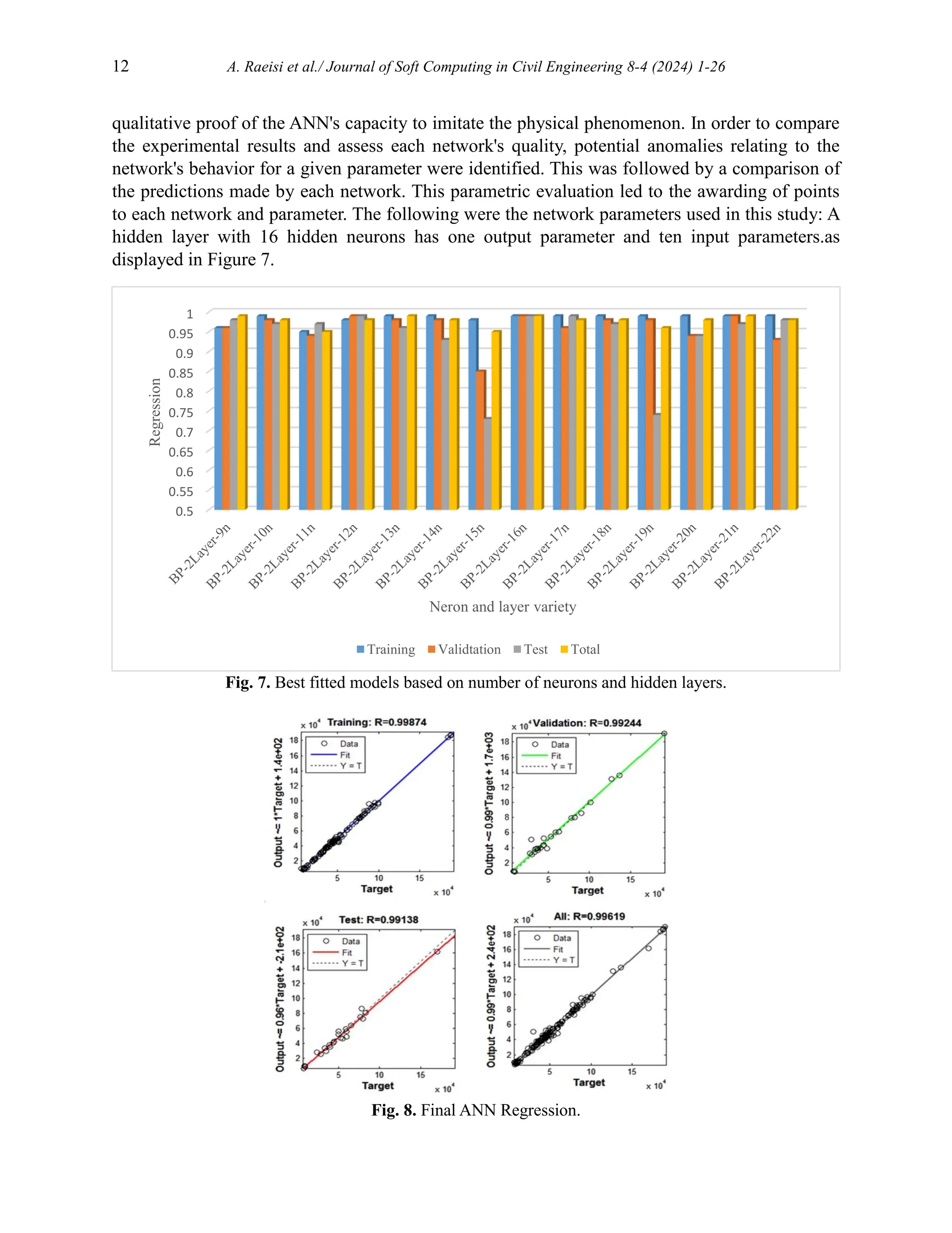
![A. Raeisi et al./ Journal of Soft Computing in Civil Engineering 8-4 (2024) 1-26 13
Fig. 9. Flexural ANN with 1 hidden layer and 16 hidden neurons.
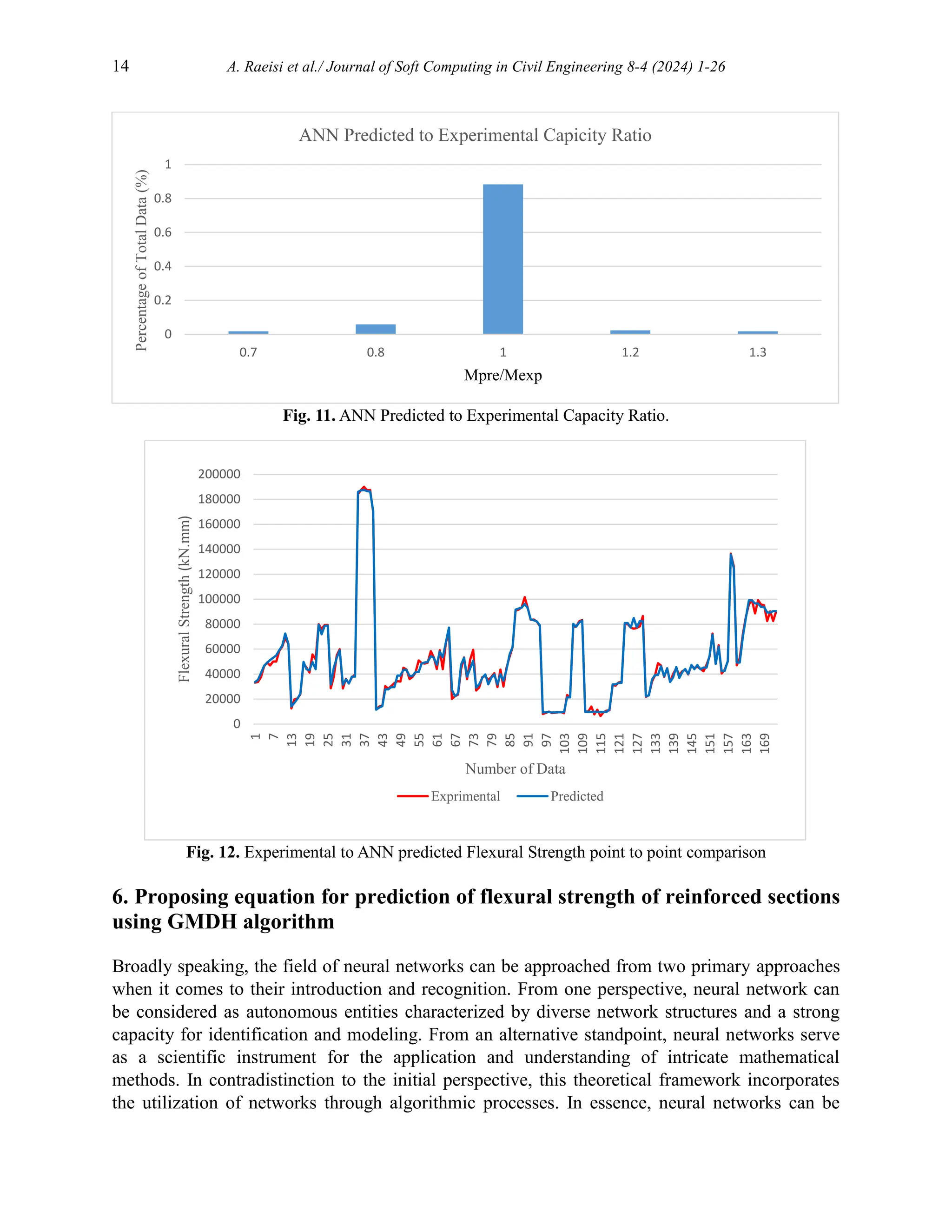
The proposed ANN model could predict the flexural strength of NSM strengthened beams with
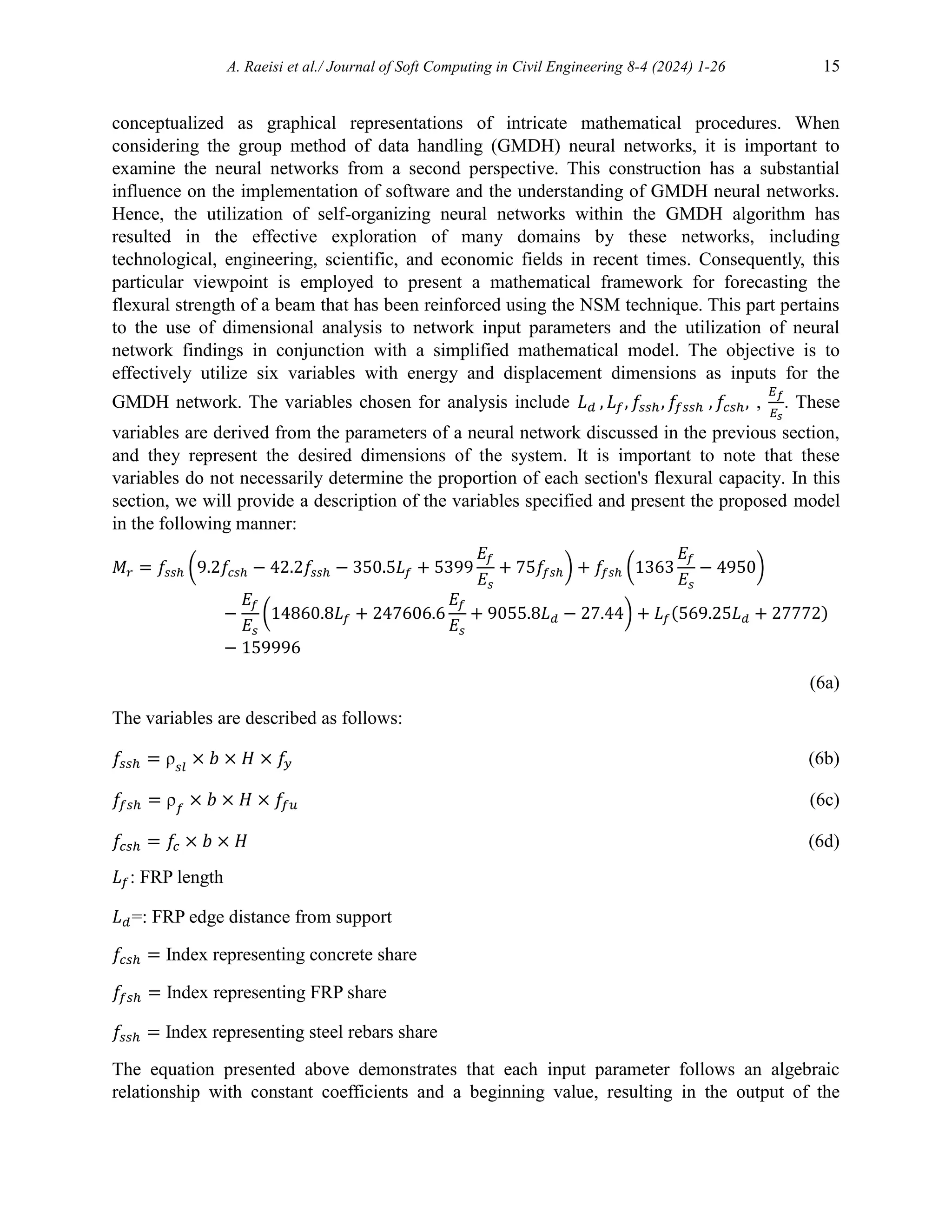
mean absolute error of just 5% in comparison to the experimental results. Figures 10 through 12
illustrate how ANNs outperform conventional models in terms of capacity prediction. However,
from the standpoint of engineering design, it may be argued that using straightforward design
equations is a more useful method for determining the strength of NSM-FRP Flexure
strengthened beams. The current study's proposal of design equations to determine the flexure
capacity of RC beams NSM-FRP strengthened in flexure is one of its objectives. In accordance
with the observed behavior of the analyses performed using neural networks, we suggest an
optimization strategy to generate simple and accurate flexure design equations for NSM-FRP
flexure reinforced RC beams. The optimization strategy is created in GMDH [24] due to the fact
that GMDH algorithms are specifically suitable for handling multi objective issues.
Fig. 10. ANN Predicted Flexural Strength comparison with Experimental.
0
20000
40000
60000
80000
100000
120000
140000
160000
180000
200000
0 20000 40000 60000 80000 100000 120000 140000 160000 180000 200000
Experimental
Flexural
Strength
(kN.mm)
Predicted Flexural Strength (kN.mm)](https://image.slidesharecdn.com/sccevolume8issue4pages1-26-250603072131-8b2b23e2/75/Flexural-Capacity-Prediction-of-RC-Beams-Strengthened-in-Terms-of-NSM-System-Using-Soft-Computing-13-2048.jpg)
![A. Raeisi et al./ Journal of Soft Computing in Civil Engineering 8-4 (2024) 1-26 17
Fig. 15. Point-by-point comparison of laboratory and proposed flexural strengths by equation in training
mode.
7. Comparison of the proposed equation with ACI 440.2R and FIB guideline
As indicated in the introductory section, there is currently no rule that provides a particular
equation for the flexural capacity of reinforced beams using the Near Surface Mounted (NSM)
approach. Hence, a comparison is made between the equation presented by ACI 440.2R [1],
which is utilized for the estimate of flexural capacity of reinforced beams by the external bonded
(EB) method, and the recommended equation. The equation for determining the flexural capacity
of a reinforced section using the Equivalent Bending (EB) method as specified in the ACI440.2R
regulation is derived by accounting for the contribution of each section of the element and
incorporating the safety factor 𝜸𝒇 in the calculation of the flexural strength of the section's Fiber
Reinforced Polymer (FRP) component. Based on empirical observations, it is postulated that the
fiber-reinforced polymer (FRP) profile in the specified segment attains its ultimate strength. In
the context of the regulation pertaining to external bonded reinforcement, it has been observed
that the equation proposed for determining the share of FRP flexural capacity in relation to the
total capacity does not incorporate the safety factor 𝜸𝒇. The equation governing the regulation
and its associated variables are delineated as follows:
𝑀𝑅𝑑 = 𝐴𝑠𝑙 × 𝑓𝑠𝑦𝑑(𝑑𝑠 − 0.4𝑥) + 𝛾𝑓𝐴𝑓𝑓
𝑓𝑒(ℎ − 0.4𝑥) (7a)
𝑓𝑓𝑒 = 𝐸𝑓 ∗ Ɛ𝑓𝑢 (7b)
𝛾𝑓 = 0.85 (7c)
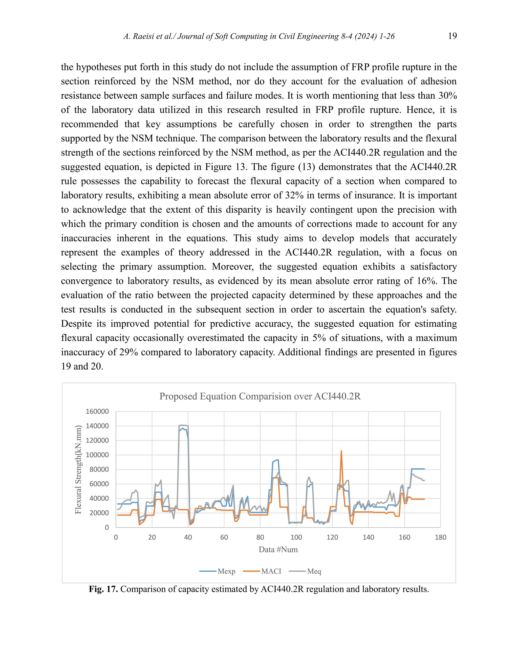
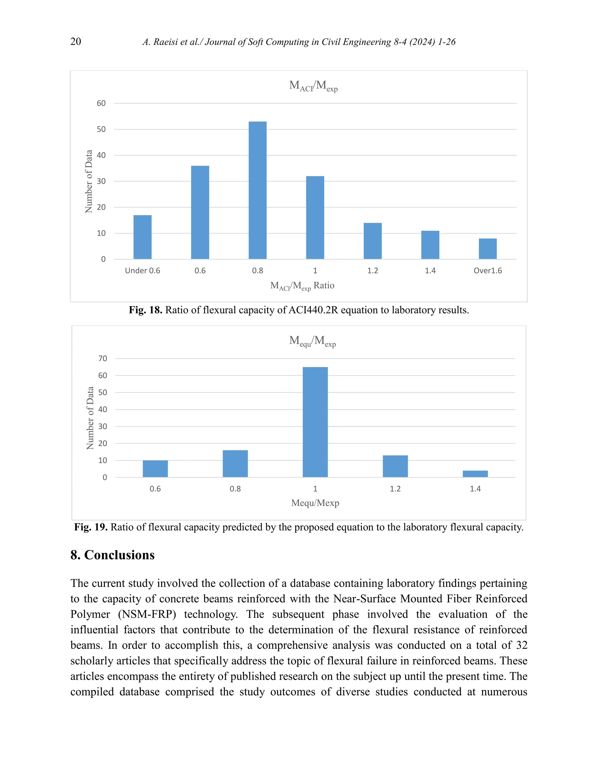
The comparison between the flexural capacity of the section, as determined by the ACI440.2R
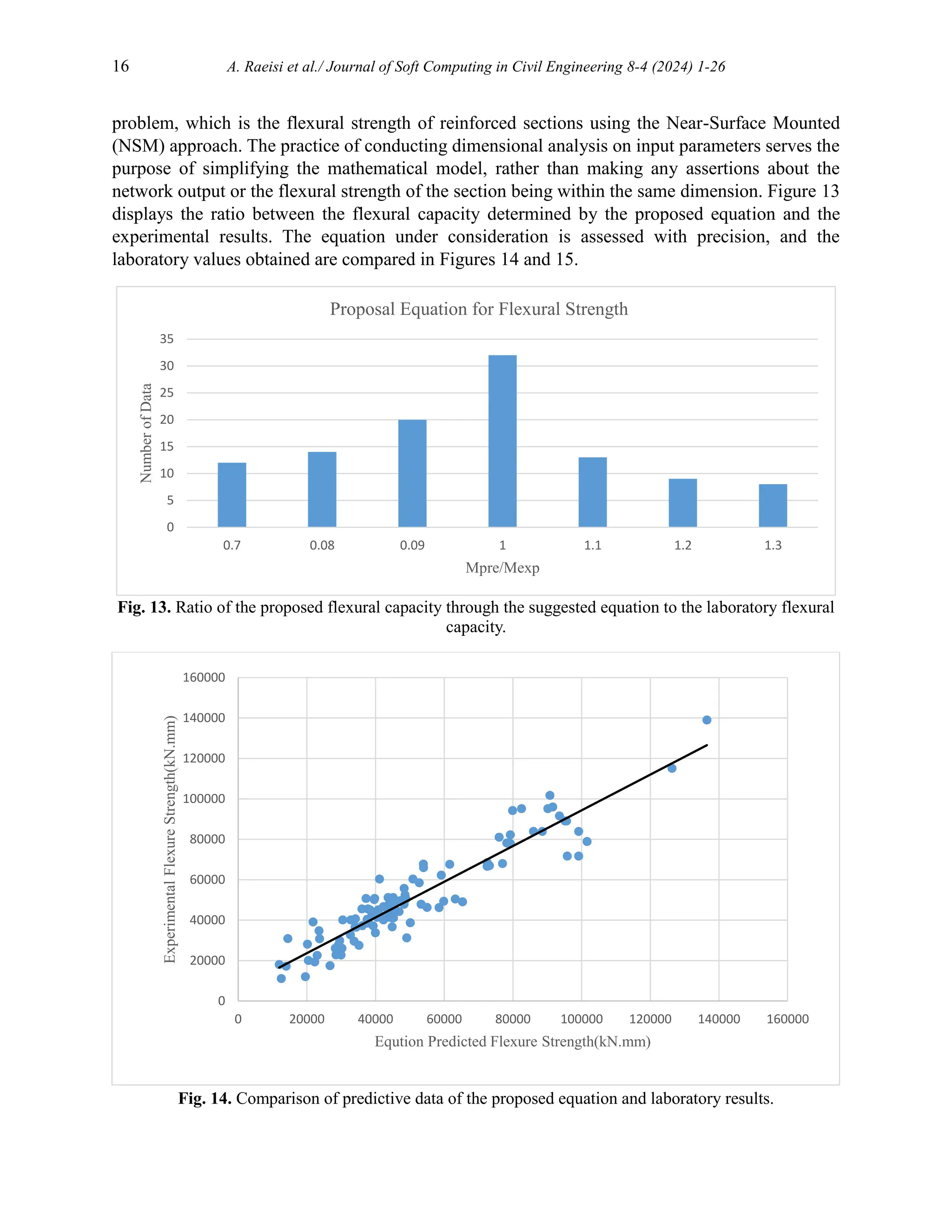
regulation, and the flexural capacity estimated by the proposed model, is presented in Figure 17
alongside the test data. Based on the visual representation provided, it can be inferred that the
occurrence of FRP rupture resulted in a notable disparity between the flexural capacity as
estimated by regulatory guidelines and the outcomes obtained from laboratory experimentation.
This assumption highlights a significant discrepancy in the ability to accurately predict the](https://image.slidesharecdn.com/sccevolume8issue4pages1-26-250603072131-8b2b23e2/75/Flexural-Capacity-Prediction-of-RC-Beams-Strengthened-in-Terms-of-NSM-System-Using-Soft-Computing-17-2048.jpg)
![18 A. Raeisi et al./ Journal of Soft Computing in Civil Engineering 8-4 (2024) 1-26
flexural capacity of a section reinforced by the Near-Surface Mounted (NSM) method compared
to the Externally Bonded (EB) technique. This discrepancy arises from the larger cross-sectional
area of Fiber Reinforced Polymer (FRP) profiles used in the NSM method, as opposed to the
FRP sheets employed in the EB technique. It is important to note that this assessment is
subjective and requires verification to establish its validity.
Fig. 16. Comparison of the capacity estimated by the equation of ACI440.2R regulation and laboratory
results.
In the updated edition of the ACI440.2R regulation [69], the aforementioned equation has been
substituted with the utilization of a traditional analytical equation that is based on fundamental
assumptions. The accuracy of this equation is evaluated in accordance with the calculations
performed. In these estimations, the initial assumption considers only two primary modes of
failure for the sample, namely the crushing of compressive concrete and the rupture of the FRP
profile. The accuracy and error of the dimensions of the neural axis site are taken into
consideration. Furthermore, the estimation of strain in fiber-reinforced polymer (FRP) concrete
and profile is conducted under the assumption that the strain exhibits linearity across the section.
The dominance of FRP profile rupture assumption is contingent upon the strain obtained being
greater than the maximum strain exhibited by the FRP material. Furthermore, the maximum
tensile strength of the Fiber Reinforced Polymer (FRP) profile is considered to be the utmost
measure of energy and strain. Subsequently, the strain and energy of metal rebar are computed by
employing the principle of strain adaptation within the section. The determination of the neutral
axis location is achieved by employing mathematical formulae, which are afterwards utilized to
evaluate its position. This computed value is then compared to the initial assumption made, and
any necessary adjustments are made accordingly. The method presents challenges in both the
initial determination and subsequent verification of the primary estimate for the neutral axis,
which can impact the overall accuracy of the final selection. Furthermore, it should be noted that
0
50000
100000
150000
200000
250000
300000
0 20 40 60 80 100 120 140 160 180
Flexural
Strength(kN.mm)
Data #Num
Proposed Equation Comparision over ACI440.2Rcode
Mexp MACI Meq](https://image.slidesharecdn.com/sccevolume8issue4pages1-26-250603072131-8b2b23e2/75/Flexural-Capacity-Prediction-of-RC-Beams-Strengthened-in-Terms-of-NSM-System-Using-Soft-Computing-18-2048.jpg)
![22 A. Raeisi et al./ Journal of Soft Computing in Civil Engineering 8-4 (2024) 1-26
Conflicts of interest
The authors declare no conflict of interest.
Authors contribution statement
A.R, H.N, M.K: Conceptualization; A.R, P.F: Data curation; A.R, H.N, M.K: Formal analysis;
A.R, P.F: Investigation; A.R, H.N, M.K: Methodology; H.N, M.K: Project administration; FA:
Resources; A.R: Software; H.N, M.K: Supervision; H.N, M.K: Validation; A.R: Visualization;
A.R, H.N, M.K: Roles/Writing – original draft; A.R, H.N, M.K, P.F: Writing – review & editing.
References
[1] 440.2R-17: Guide for the Design and Construction of Externally Bonded FRP Systems for
Strengthening Concrete Structures. 2017. https://doi.org/10.14359/51700867.
[2] Effiong JU, Ede AN. Experimental Investigation on the Strengthening of Reinforced Concrete
Beams Using Externally Bonded and Near-Surface Mounted Natural Fibre Reinforced Polymer
Composites—A Review. Materials (Basel) 2022;15:5848. https://doi.org/10.3390/ma15175848.
[3] Bilotta A, Ceroni F, Di Ludovico M, Nigro E, Pecce M, Manfredi G. Bond Efficiency of EBR and
NSM FRP Systems for Strengthening Concrete Members. J Compos Constr 2011;15:757–72.
https://doi.org/10.1061/(ASCE)CC.1943-5614.0000204.
[4] Lorenzis L De, Nanni A, Tegola A La. Strengthening of Reinforced Concrete Structures with Near
Surface Mounted FRP Rods. Int. Meet. Compos. Mater., 2000, p. 1–8.
[5] De Lorenzis L, Nanni A. Bond between near-surface mounted fiber-reinforced polymer rods and
concrete in structural strengthening. ACI Struct J 2002;99:123–32. https://doi.org/10.14359/11534.
[6] El-Hacha R, Rizkalla SH, Kotynia R. Modelling of Reinforced Concrete Flexural Members
Strengthened with Near-Surface Mounted FRP Reinforcement. SP-230 7th Int. Symp. Fiber-
Reinforced Polym. Reinf. Concr. Struct., vol. SP-230, American Concrete Institute; 2005, p. 1681–
700. https://doi.org/10.14359/14916.
[7] Taleb Obaidat Y, Barham WS, Aljarah AH. New anchorage technique for NSM-CFRP flexural
strengthened RC beam using steel clamped end plate. Constr Build Mater 2020;263:120246.
https://doi.org/10.1016/j.conbuildmat.2020.120246.
[8] Jalali M, Sharbatdar MK, Chen J-F, Jandaghi Alaee F. Shear strengthening of RC beams using
innovative manually made NSM FRP bars. Constr Build Mater 2012;36:990–1000.
https://doi.org/10.1016/j.conbuildmat.2012.06.068.
[9] Teng JG, De Lorenzis L, Wang B, Li R, Wong TN, Lam L. Debonding Failures of RC Beams
Strengthened with Near Surface Mounted CFRP Strips. J Compos Constr 2006;10:92–105.
https://doi.org/10.1061/(ASCE)1090-0268(2006)10:2(92).
[10] Sharaky IA, Torres L, Comas J, Barris C. Flexural response of reinforced concrete (RC) beams
strengthened with near surface mounted (NSM) fibre reinforced polymer (FRP) bars. Compos
Struct 2014;109:8–22. https://doi.org/10.1016/j.compstruct.2013.10.051.
[11] Hassan TK, Rizkalla SH. Bond Mechanism of Near-Surface-Mounted Fiber-Reinforced Polymer
Bars for Flexural Strengthening of Concrete Structures. ACI Struct J 2004;101:830–9.
https://doi.org/10.14359/13458.](https://image.slidesharecdn.com/sccevolume8issue4pages1-26-250603072131-8b2b23e2/75/Flexural-Capacity-Prediction-of-RC-Beams-Strengthened-in-Terms-of-NSM-System-Using-Soft-Computing-22-2048.jpg)
![A. Raeisi et al./ Journal of Soft Computing in Civil Engineering 8-4 (2024) 1-26 23
[12] Nordin H, Täljsten B. Concrete Beams Strengthened with Prestressed Near Surface Mounted
CFRP. J Compos Constr 2006;10:60–8. https://doi.org/10.1061/(ASCE)1090-0268(2006)10:1(60).
[13] Kara IF, Ashour AF, Köroğlu MA. Flexural performance of reinforced concrete beams
strengthened with prestressed near-surface-mounted FRP reinforcements. Compos Part B Eng
2016;91:371–83. https://doi.org/10.1016/j.compositesb.2016.01.023.
[14] Seo S, Choi K, Kwon Y, Lee K. Flexural Strength of RC Beam Strengthened by Partially De-
bonded Near Surface-Mounted FRP Strip. Int J Concr Struct Mater 2016;10:149–61.
https://doi.org/10.1007/s40069-016-0133-z.
[15] Wu G, Dong Z, Wu Z, Zhang L. Performance and Parametric Analysis of Flexural Strengthening
for RC Beams with NSM-CFRP Bars. J Compos Constr 2014;18:1–10.
https://doi.org/10.1061/(ASCE)CC.1943-5614.0000451.
[16] Costa IG, Barros JAO. Flexural and shear strengthening of RC beams with composite materials –
The influence of cutting steel stirrups to install CFRP strips. Cem Concr Compos 2010;32:544–53.
https://doi.org/10.1016/j.cemconcomp.2010.03.003.
[17] Tang WC, Balendran RV, Nadeem A, Leung HY. Flexural strengthening of reinforced lightweight
polystyrene aggregate concrete beams with near-surface mounted GFRP bars. Build Environ
2006;41:1381–93. https://doi.org/10.1016/j.buildenv.2005.05.029.
[18] Boukhezar M, Samai ML, Mesbah HA, Houari H. Flexural behaviour of reinforced low-strength
concrete beams strengthened with CFRP plates. Struct Eng Mech 2013;47:819–38.
https://doi.org/10.12989/sem.2013.47.6.819.
[19] Barros J, Sena-cruz J, Dias S, Ferreira D, Fortes A. Near surface mounted CFRP-based technique
for the strengthening of concrete structures. Concrete 2004:1–13.
[20] Ceroni F. Experimental performances of RC beams strengthened with FRP materials. Constr Build
Mater 2010;24:1547–59. https://doi.org/10.1016/j.conbuildmat.2010.03.008.
[21] Soliman SM, El-Salakawy E, Benmokrane B. Flexural behaviour of concrete beams strengthened
with near surface mounted fibre reinforced polymer bars. Can J Civ Eng 2010;37:1371–82.
https://doi.org/10.1139/L10-077.
[22] Barris C, Sala P, Gómez J, Torres L. Flexural behaviour of FRP reinforced concrete beams
strengthened with NSM CFRP strips. Compos Struct 2020;241:112059.
https://doi.org/10.1016/j.compstruct.2020.112059.
[23] Lee S, Lee C. Prediction of shear strength of FRP-reinforced concrete flexural members without
stirrups using artificial neural networks. Eng Struct 2014;61:99–112.
https://doi.org/10.1016/j.engstruct.2014.01.001.
[24] Naderpour H, Poursaeidi O, Ahmadi M. Shear resistance prediction of concrete beams reinforced
by FRP bars using artificial neural networks. Measurement 2018;126:299–308.
https://doi.org/10.1016/j.measurement.2018.05.051.
[25] Cortez P, Embrechts MJ. Using sensitivity analysis and visualization techniques to open black box
data mining models. Inf Sci (Ny) 2013;225:1–17. https://doi.org/10.1016/j.ins.2012.10.039.
[26] Ghanizadeh AR, Ghanizadeh A, Asteris PG, Fakharian P, Armaghani DJ. Developing bearing
capacity model for geogrid-reinforced stone columns improved soft clay utilizing MARS-EBS
hybrid method. Transp Geotech 2023;38:100906. https://doi.org/10.1016/j.trgeo.2022.100906.
[27] Chen L, Fakharian P, Rezazadeh Eidgahee D, Haji M, Mohammad Alizadeh Arab A, Nouri Y.
Axial compressive strength predictive models for recycled aggregate concrete filled circular steel
tube columns using ANN, GEP, and MLR. J Build Eng 2023;77:107439.
https://doi.org/10.1016/j.jobe.2023.107439.](https://image.slidesharecdn.com/sccevolume8issue4pages1-26-250603072131-8b2b23e2/75/Flexural-Capacity-Prediction-of-RC-Beams-Strengthened-in-Terms-of-NSM-System-Using-Soft-Computing-23-2048.jpg)
![24 A. Raeisi et al./ Journal of Soft Computing in Civil Engineering 8-4 (2024) 1-26
[28] Chen Q, Norcio AF, Wang J. Neural Network Based Stereotyping for User Profiles. Neural
Comput Appl 2000;9:259–65. https://doi.org/10.1007/s005210070003.
[29] Naderpour H, Haji M, Mirrashid M. Shear capacity estimation of FRP-reinforced concrete beams
using computational intelligence. Structures 2020;28:321–8.
https://doi.org/10.1016/j.istruc.2020.08.076.
[30] Naderpour H, Kheyroddin A, Amiri GG. Prediction of FRP-confined compressive strength of
concrete using artificial neural networks. Compos Struct 2010;92:2817–29.
https://doi.org/10.1016/j.compstruct.2010.04.008.
[31] Naderpour H, Alavi SA. A proposed model to estimate shear contribution of FRP in strengthened
RC beams in terms of Adaptive Neuro-Fuzzy Inference System. Compos Struct 2017;170:215–27.
https://doi.org/10.1016/j.compstruct.2017.03.028.
[32] Naderpour H, Rafiean AH, Fakharian P. Compressive strength prediction of environmentally
friendly concrete using artificial neural networks. J Build Eng 2018;16:213–9.
https://doi.org/10.1016/j.jobe.2018.01.007.
[33] Fakharian P, Rezazadeh Eidgahee D, Akbari M, Jahangir H, Ali Taeb A. Compressive strength
prediction of hollow concrete masonry blocks using artificial intelligence algorithms. Structures
2023;47:1790–802. https://doi.org/10.1016/j.istruc.2022.12.007.
[34] Mehany S, Mohamed HM, Benmokrane B. Flexural Behavior and Serviceability Performance of
Lightweight Self-Consolidating Concrete Beams Reinforced with Basalt Fiber-Reinforced Polymer
Bars. ACI Struct J 2023;120:47–60. https://doi.org/10.14359/51738502.
[35] Uzdil O, Sayın B, Coşgun T. Examination of parameters impacting flexural and shear
strengthening of RC beams. J Struct Eng Appl Mech 2022;5:117–34.
https://doi.org/10.31462/jseam.2022.03117134.
[36] Askar MK, Hassan AF, Al-Kamaki YSS. Flexural and shear strengthening of reinforced concrete
beams using FRP composites: A state of the art. Case Stud Constr Mater 2022;17:e01189.
https://doi.org/10.1016/j.cscm.2022.e01189.
[37] Al-Obaidi S, Saeed YM, Rad FN. Flexural strengthening of reinforced concrete beams with NSM-
CFRP bars using mechanical interlocking. J Build Eng 2020;31:101422.
https://doi.org/10.1016/j.jobe.2020.101422.
[38] Panahi M, Zareei SA, Izadi A. Flexural strengthening of reinforced concrete beams through
externally bonded FRP sheets and near surface mounted FRP bars. Case Stud Constr Mater
2021;15:e00601. https://doi.org/10.1016/j.cscm.2021.e00601.
[39] Suliman AKS, Jia Y, Mohammed AAA. Experimental evaluation of factors affecting the behaviour
of reinforced concrete beams strengthened by NSM CFRP strips. Structures 2021;32:632–40.
https://doi.org/10.1016/j.istruc.2021.03.058.
[40] Al-Abdwais AH, Al-Mahaidi RS. Experimental and finite element analysis of flexural performance
of RC beams retrofitted using near-surface mounted with CFRP composites and cement adhesive.
Eng Struct 2021;241:112429. https://doi.org/10.1016/j.engstruct.2021.112429.
[41] Jahani Y, Baena M, Gómez J, Barris C, Torres L. Experimental Study of the Effect of High Service
Temperature on the Flexural Performance of Near-Surface Mounted (NSM) Carbon Fiber-
Reinforced Polymer (CFRP)-Strengthened Concrete Beams. Polymers (Basel) 2021;13:920.
https://doi.org/10.3390/polym13060920.
[42] Murad Y, Abu-AlHaj T. Flexural strengthening and repairing of heat damaged RC beams using
continuous near-surface mounted CFRP ropes. Structures 2021;33:451–62.
https://doi.org/10.1016/j.istruc.2021.04.079.](https://image.slidesharecdn.com/sccevolume8issue4pages1-26-250603072131-8b2b23e2/75/Flexural-Capacity-Prediction-of-RC-Beams-Strengthened-in-Terms-of-NSM-System-Using-Soft-Computing-24-2048.jpg)
![A. Raeisi et al./ Journal of Soft Computing in Civil Engineering 8-4 (2024) 1-26 25
[43] Abdallah M, Al Mahmoud F, Khelil A, Mercier J, Almassri B. Assessment of the flexural behavior
of continuous RC beams strengthened with NSM-FRP bars, experimental and analytical study.
Compos Struct 2020;242:112127. https://doi.org/10.1016/j.compstruct.2020.112127.
[44] Imjai T, Setkit M, Garcia R, Figueiredo FP. Strengthening of damaged low strength concrete beams
using PTMS or NSM techniques. Case Stud Constr Mater 2020;13:e00403.
https://doi.org/10.1016/j.cscm.2020.e00403.
[45] Yazdani N, Aljaafreh T, Beneberu E. Concrete beam flexural strengthening with anchored pre-
saturated CFRP laminates. Compos Struct 2020;235:111733.
https://doi.org/10.1016/j.compstruct.2019.111733.
[46] Abdelkarim OI, Ahmed EA, Mohamed HM, Benmokrane B. Flexural strength and serviceability
evaluation of concrete beams reinforced with deformed GFRP bars. Eng Struct 2019;186:282–96.
https://doi.org/10.1016/j.engstruct.2019.02.024.
[47] Obaidat YT, Ashteyat AM, Obaidat AT. Performance of RC Beam Strengthened with NSM-CFRP
Strip Under Pure Torsion: Experimental and Numerical Study. Int J Civ Eng 2020;18:585–93.
https://doi.org/10.1007/s40999-019-00487-2.
[48] Panahi M, Izadinia M. A Parametric Study on the Flexural Strengthening of Reinforced Concrete
Beams with Near Surface Mounted FRP Bars. Civ Eng J 2018;4:1917. https://doi.org/10.28991/cej-
03091126.
[49] Sharaky IA, Baena M, Barris C, Sallam HEM, Torres L. Effect of axial stiffness of NSM FRP
reinforcement and concrete cover confinement on flexural behaviour of strengthened RC beams:
Experimental and numerical study. Eng Struct 2018;173:987–1001.
https://doi.org/10.1016/j.engstruct.2018.07.062.
[50] Yaseen SA. Flexural Behavior of Self Compacting Concrete T-Beams Reinforced with AFRP.
Eurasian J Sci Eng 2018;4. https://doi.org/10.23918/eajse.v4i2p178.
[51] Daghash SM, Ozbulut OE. Flexural performance evaluation of NSM basalt FRP-strengthened
concrete beams using digital image correlation system. Compos Struct 2017;176:748–56.
https://doi.org/10.1016/j.compstruct.2017.06.021.
[52] Haddad RH, Almomani OA. Recovering flexural performance of thermally damaged concrete
beams using NSM CFRP strips. Constr Build Mater 2017;154:632–43.
https://doi.org/10.1016/j.conbuildmat.2017.07.211.
[53] Al-Saadi NTK, Mohammed A, Al-Mahaidi R. Performance of RC beams rehabilitated with NSM
CFRP strips using innovative high-strength self-compacting cementitious adhesive (IHSSC-CA)
made with graphene oxide. Compos Struct 2017;160:392–407.
https://doi.org/10.1016/j.compstruct.2016.10.084.
[54] Goldston MW, Remennikov A, Sheikh MN. Flexural behaviour of GFRP reinforced high strength
and ultra high strength concrete beams. Constr Build Mater 2017;131:606–17.
https://doi.org/10.1016/j.conbuildmat.2016.11.094.
[55] Khalifa AM. Flexural performance of RC beams strengthened with near surface mounted CFRP
strips. Alexandria Eng J 2016;55:1497–505. https://doi.org/10.1016/j.aej.2016.01.033.
[56] Mahal M, Täljsten B, Blanksvärd T. Experimental performance of RC beams strengthened with
FRP materials under monotonic and fatigue loads. Constr Build Mater 2016;122:126–39.
https://doi.org/10.1016/j.conbuildmat.2016.06.060.
[57] Yang JM, Min KH, Shin HO, Yoon YS. Behavior of High-Strength Concrete Beams Reinforced
with Different Types of Flexural Reinforcement and Fiber. Adv. FRP Compos. Civ. Eng., vol. L,
Berlin, Heidelberg: Springer Berlin Heidelberg; 2011, p. 275–8. https://doi.org/10.1007/978-3-642-
17487-2_58.](https://image.slidesharecdn.com/sccevolume8issue4pages1-26-250603072131-8b2b23e2/75/Flexural-Capacity-Prediction-of-RC-Beams-Strengthened-in-Terms-of-NSM-System-Using-Soft-Computing-25-2048.jpg)
![26 A. Raeisi et al./ Journal of Soft Computing in Civil Engineering 8-4 (2024) 1-26
[58] Nurbaiah MN, Hanizah AH, Nursafarina A, Nur Ashikin M. Flexural behaviour of RC beams
strengthened With externally bonded (EB) FRP sheets or Near Surface Mounted (NSM) FRP rods
method. 2010 Int. Conf. Sci. Soc. Res. (CSSR 2010), IEEE; 2010, p. 1232–7.
https://doi.org/10.1109/CSSR.2010.5773725.
[59] Al-mahmoud F, Castel A, François R, Tourneur C. RC beams strengthened with NSM CFRP rods
and modeling of peeling-off failure 2010;92:1920–30.
https://doi.org/10.1016/j.compstruct.2010.01.002.
[60] Akbarzadeh H, Maghsoudi AA. Experimental and analytical investigation of reinforced high
strength concrete continuous beams strengthened with fiber reinforced polymer. Mater Des
2010;31:1130–47. https://doi.org/10.1016/j.matdes.2009.09.041.
[61] Perera R, Vique J, Arteaga A, Diego A De. Shear capacity of reinforced concrete members
strengthened in shear with FRP by using strut-and-tie models and genetic algorithms. Compos Part
B Eng 2009;40:714–26. https://doi.org/10.1016/j.compositesb.2009.06.008.
[62] Wang B, Teng JG, Lorenzis L De, Zhou L, Ou J, Jin W, et al. Strain monitoring of RC members
strengthened with smart NSM FRP bars. Constr Build Mater 2009;23:1698–711.
https://doi.org/10.1016/j.conbuildmat.2008.07.027.
[63] Al-Mahmoud F, Castel A, François R, Tourneur C. Strengthening of RC members with near-
surface mounted CFRP rods. Compos Struct 2009;91:138–47.
https://doi.org/10.1016/j.compstruct.2009.04.040.
[64] Hashemi SH, Rahgozar R, Maghsoudi AA. Flexural testing of high strength reinforced concrete
beams strengthened with CFRP sheets. Int J Eng Trans B Appl 2009;22:131–46.
[65] Barros JAO, Dias SJE, Lima JLT. Efficacy of CFRP-based techniques for the flexural and shear
strengthening of concrete beams. Cem Concr Compos 2007;29:203–17.
https://doi.org/10.1016/j.cemconcomp.2006.09.001.
[66] Hassan T, Rizkalla S. Investigation of Bond in Concrete Structures Strengthened with Near Surface
Mounted Carbon Fiber Reinforced Polymer Strips. J Compos Constr 2003;7:248–57.
https://doi.org/10.1061/(ASCE)1090-0268(2003)7:3(248).
[67] Jung WT, Park YH, Park JS, Kang JY, You YJ. Experimental investigation on flexural behavior of
RC beams strengthened by NSM CFRP reinforcements. Am. Concr. Institute, ACI Spec. Publ., vol.
SP-230, 2005, p. 795–805.
[68] Barros J, Kotynia R. Possibilities and challenges of NSM for the flexural strengthening of RC
structures. Proc. 4th Int. Conf. FRP Compos. Civ. Eng. CICE 2008, 2008, p. 22–4.
[69] Soudki K, Alkhrdaji T. Guide for the Design and Construction of Externally Bonded FRP Systems
for Strengthening Concrete Structures (ACI 440.2R-02). Struct. Congr. 2005, Reston, VA:
American Society of Civil Engineers; 2005, p. 1–8. https://doi.org/10.1061/40753(171)159.](https://image.slidesharecdn.com/sccevolume8issue4pages1-26-250603072131-8b2b23e2/75/Flexural-Capacity-Prediction-of-RC-Beams-Strengthened-in-Terms-of-NSM-System-Using-Soft-Computing-26-2048.jpg)
In recent years, there has been a notable increase in the application of near-surface mounted fiber-reinforced polymer (FRP) reinforcement in reinforced concrete structures. Nevertheless, there is a discernible disparity in the accessibility of accurate and customize measures for augmenting flexural strength through the use of near-surface mounted (NSM) reinforcement techniques. Although several basic models have been proposed to predict the flexural capacity achievable with this technology, established codes have not yet provided mathematical equations for this specific purpose. This study presents two separate methodologies with the objective of enhancing the development of suitable code provisions. In the first stage, A comprehensive and reliable database has been developed to leverage the predictive accuracy of neural networks in the computation of the flexural capacity of reinforced beams that utilize near-surface mounted reinforcement. Following this, the results obtained from the neural network are employed to construct a linear equation using the group method of data handling (GMDH) technique. The presented equation has been carefully formulated to produce a concise and simple mathematical expression that enables the determination of the flexural strength of a beam on the field. The evaluation of the accuracy and effectiveness of both the neural network and the suggested equation is conducted in accordance with the requirements specified in ACI 440.R2 for externally bonded reinforcements. The neural network's prediction has a mean absolute error of just 5% in comparison to the experimental results and the GMDH equations exhibit a noteworthy level of concurrence with the experimental outcomes, as they display a mean absolute error of 16%.


