The document proposes a novel flexible antenna designed for automotive applications, specifically for vehicular communication using the 5.9 GHz frequency band. This compact antenna is fabricated using low-cost materials like polyimide and aims to support various communication protocols including LTE and wave technologies. The design exhibits good performance characteristics such as return loss and isolation, making it suitable for integration into the vehicle's architecture.
![International Journal of Trend in Scientific Research and Development (IJTSRD) @ www.ijtsrd.com eISSN: 2456-6470
@ IJTSRD | Unique Paper ID – IJTSRD30510 | Volume – 4 | Issue – 3 | March-April 2020 Page 481
lower band it is not much and the design of other antennas
for different services can be limited by the available volume
of the flexible case .The modified monopole antennas are
designed for WAVE application.
The antennas have been designed by using the Computer
Software Technology (CST).The antenna is designed on the
0.008 mm thick polyimide substrate with permittivity of 4.4
and loss tangent of 0.009. The vertically collinear reception
apparatus cluster witha productiveradiationprocedurewas
utilized as monopole to get high-gain radiation design in
azimuth plane and diminish side lobes in rise plane. The
absolute length of the receiving antenna is around two and
quarter wavelengths.
The stage inversion segments of the complete length were
dropped by utilizing the stub and the by means of on the
printed circuit board. The simulated surface current
distribution at 5.9 GHz for the antenna sections. Theflows of
the stage inversion area are effectively smoothened by the
proposed structures.
III. SIMULATION OF ANTENNA
The simulated and estimated S-parameters of the full
antenna structure. Framework are investigated Each
receiving signal was estimated while the others were ended
at 50 Ω loads. A decent understanding between the
recreation and the estimation is affirmed for the entire
working groups with the exception of a little recurrence
move of the WAVE groups, whichisinall probabilitybrought
about by an off base portrayal of the polyimide permittivity.
The return loss of monopole antenna for WAVE band are
better than 10dB. For antenna applications,theECC(Envelop
Correlation Coefficient) is generally used to calculate the
channel capacity and cross-correlation performances. The
calculated ECC of the antenna is always lower than the 0.5
for the whole LTE low band, which is practicallyaccepted for
the antenna diversity.
The adequate ECC estimation of the proposed reception
antenna was effectively accomplished without extra
separation methods.
Simulation results shows that the radiation efficiency of the
monopole antenna is highly dependent on the mutual
coupling and termination impedance of the other band
antennas. Finally, gain patterns were measured in a field
monitors using a far-field results and a vector network
analyzer.
The proposed antenna was mounted on a 54mm × 47mm
metallic plane to incorporate the car rooftop impact shows
the simulated and measured gain patterns of the proposed
antenna solution integrated on the finite ground plane.
The proposed MIMO-LTE reception antenna have
moderately low profile and smaller size inside restricted
volume, and accomplish great separation qualities from
other integrated antennas comparedwithpast examinations
for vehicular applications.
IV. FLEXIBLE SUBSTRATE
Flexible electronics can presently be viewed as a settled
innovation that has arrived at a specificlevel ofdevelopment
in meeting the necessities of firmly assembled electronic
packages, providingreliable electrical connectionswherethe
assembly is required to flex during its typical use or where
board thickness, weight, or space imperatives are driving
elements.
In this context, flexible substrate antennas (FSAs) assume a
key job in the combination and packing of wire-less
communication gadgets and sensor systems.
In this chapter Flexible printed monopole antenna based on
Kapton Polyimide substrate. Polyimide film was chosen as
the antenna substrate in due to its good balance of physical,
chemical, and electrical properties with a low loss factor
over a wide frequency range (tan δ=0.002). Furthermore,
Polyimide offers a very low profile (50.8 μm)yetvery robust
with a tensile strength of 165 MPa at 73°F, a dielectric
strength of 3500-7000volts/mil,anda temperature ratingof
-65 to 150°C [10]. Other Polymer based and synthesized
flexible substrates have been also used in several designs.
In addition, the performance of the antenna is assessed
under bending impacts in termsofimpedance matchingshift
in resonant frequency. Finally, the characteristic of the
antenna under investigation are contrasted with a few
adaptable antennas.
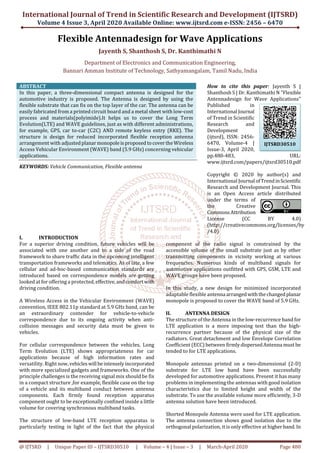
V. MODULE FLOW
Fig.1
VI. SYSTEM ARCHITECTURE
Fig.2.a Monopole Antenna](https://image.slidesharecdn.com/95flexibleantennadesign-200531102400/85/Flexible-Antennadesign-for-Wave-Applications-2-320.jpg)
![International Journal of Trend in Scientific Research and Development (IJTSRD) @ www.ijtsrd.com eISSN: 2456-6470
@ IJTSRD | Unique Paper ID – IJTSRD30510 | Volume – 4 | Issue – 3 | March-April 2020 Page 482
Fig 2.b WAVE frequency of Monopole antenna
(5.9GHz)
Fig 3.a Bending of flexible polyimide substrate
Fig 3.b WAVE frequency of Monopole antenna
(radius=5)
Fig 4.a Bending of flexible polyimide substrate
Fig 4.b WAVE frequency of Monopole antenna
(radius=15)
Fig5.a bending of flexible polyimide substrate
Fig 5.b WAVE frequency of Monopole antenna
(radius=10)
The antenna with the polyimide substrate of radius=5 gives
the frequency of 5.8GHz as shown in Fig3.b.substrate with
the bending of radius=10 gives the output frequency of 6
GHz as shown in Fig 5.b .Flexible substrate with the
radius=15 shows the WAVE frequency of automobile
application 5.9 GHz as shown in Fig 4.b
VII. CONCLUSION
A new compact antenna solution covering LTE, for WAVE
bands (5.9 GHz) that is fully integrated in the flexible
polyimide substrate was proposed for automotive
applications. The solution consists of a modified monopole,
and a separate patch with easy and low-cost fabrication
process. The solution is designed to fit in a roof of the car
mounted on a finite ground plane. The simulation and the
measurement results show that the antenna systemexhibits
good performances for return loss, radiation pattern, and
isolation characteristics without matching network or
decoupling techniques.
REFERENCES
[1] D. V. Navarro-Mendez et al., “Wideband double
monopole for mobile, WLAN and C2C services in
vehicular applications,” IEEE Antennas Wire-less
Propag. Lett., vol. 16, pp.16–19, 2017.
[2] Haider R. Khaleel, Hussain M. Al-Rizzo and Ayman I.
Design, Fabrication, and Testing of Flexible Antennas,
Advancement in Micro strip Antennas with Recent
Applications.(March 6th 2013).](https://image.slidesharecdn.com/95flexibleantennadesign-200531102400/85/Flexible-Antennadesign-for-Wave-Applications-3-320.jpg)
![International Journal of Trend in Scientific Research and Development (IJTSRD) @ www.ijtsrd.com eISSN: 2456-6470
@ IJTSRD | Unique Paper ID – IJTSRD30510 | Volume – 4 | Issue – 3 | March-April 2020 Page 483
[3] Hendrik Rogier, AnaCollado, ManosTentzeris And
Carles Fernández-Prades, International Journal of
Antennas and Propagation ,Flexible Substrate
Antnnas.(August 2012).
[4] O. Y. Kwon, R. Song, Y. Z. Ma, and B. S. Kim, “Integrated
MIMO antennas for LTE and V2V applications,”inProc.
URSI Asia-Pac. Radio Science Conf., Seoul, South
Korea,2016, pp. 1057–1060.
[5] N. Guan, H. Tayama, M. Ueyama, Y. Yoshijima, and H.
Chiba, “A roof automobile module for LTE-MIMO
antennas,” in Proc. IEEE-APS Topical Conf. Antennas
Propag. Wireless Commun., Turin, Italy, 2015,pp.387–
391.
[6] Topical Conf. Antennas Propag. Wireless Commun.,
2014, pp. 89–92. M. Geissler, K. Scharwies,andJ.Christ,
“Intelligent antenna systems for cars,” in Proc. German
Microw. Conf., Aachen, Germany, 2014.
[7] "IEEE Antennas and Wireless Propagation Letters," in
IEEE Antennas Wireless And Propogation Letters, vol.
17, no. 4, pp. C2-C2, April 2018](https://image.slidesharecdn.com/95flexibleantennadesign-200531102400/85/Flexible-Antennadesign-for-Wave-Applications-4-320.jpg)